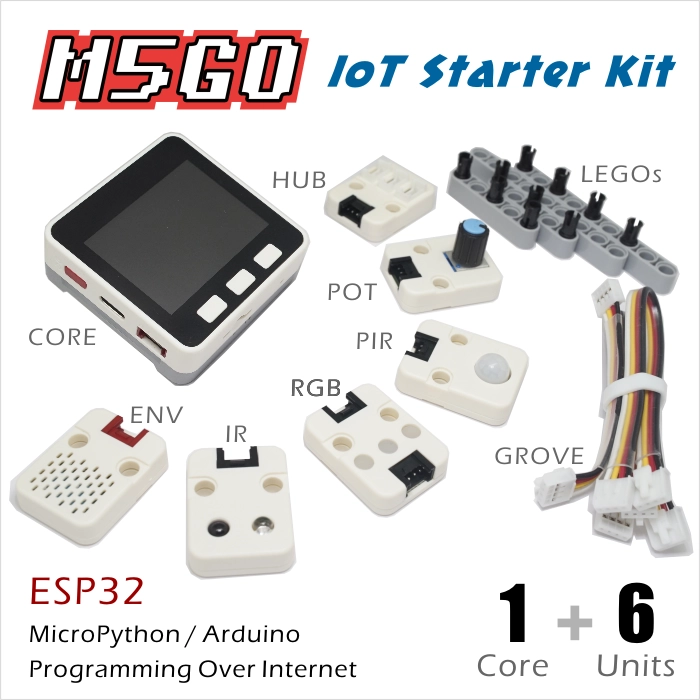
M5GO IoT Kit is a development kit in the M5Stack family that targets STEM education. In addition to the main controller M5GO, the kit includes 6 Units with different functions and various LEGO bricks and other accessories. M5GO not only provides abundant hardware resources, but also offers a wealth of teaching videos, textbooks, technical documents, and more. It plays an important role in STEM education for students of all ages. The kit comes with the cloud-based WebIDE UIFlow programming platform. By pushing code through the network, students can truly experience the power of the Internet of Things. Multiple programming options are supported, helping students gradually transition from block-based coding to understanding actual source code. As a kit designed specifically for STEM education, M5GO aims to let students gain knowledge while having fun, and enjoy the sense of accomplishment that comes from turning creative ideas into reality. Students are free to explore the world of engineering, build their own IoT products, and integrate brilliant ideas into real life.
This tutorial introduces how to control the M5GO device through the Arduino IDE
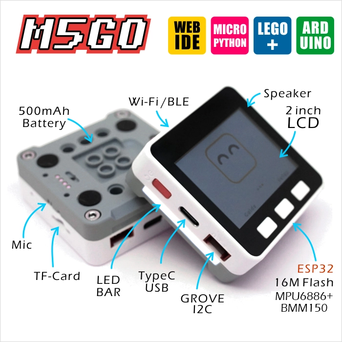
Features
ESP32-based development
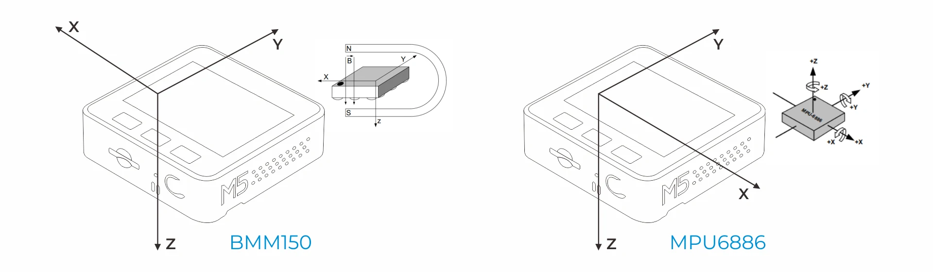
Integrated 3-axis magnetometer, 3-axis gyroscope and 3-axis accelerometer
Built-in speaker, buttons, LCD screen, power / reset button
TF card slot (up to 16 GB)
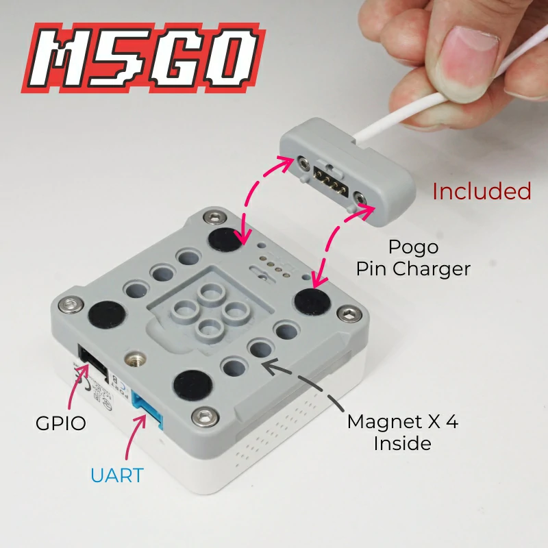
Extendable pins and interfaces
M5-Bus socket
Built-in battery
Magnetic charging on the back
Development Platform
UiFlow1
UiFlow2
Arduino IDE
ESP-IDF
PlatformIO
Includes
1 x M5GO
6 x Units (Unit ENV-II, Unit PIR, Unit Angle, Unit IR, Unit RGB, Unit Hub)
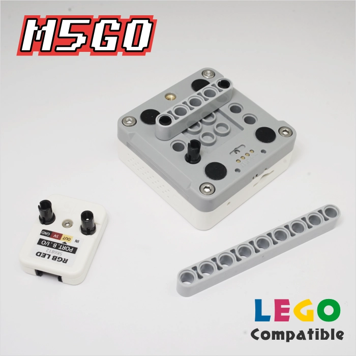
4 x LEGO bricks
12 x LEGO connectors
4 x GROVE cables
1 x USB Type-C Cable (20 cm)
1 x M2 × 12 machine screw
2 x M3 × 16 machine screws
1 x Hex Key L-Shape 1.5 mm (For M2 Screw)
1 x User Manual
Applications
IoT controller
STEM education
DIY projects
Smart-home devices
Specifications
Specification
Parameter
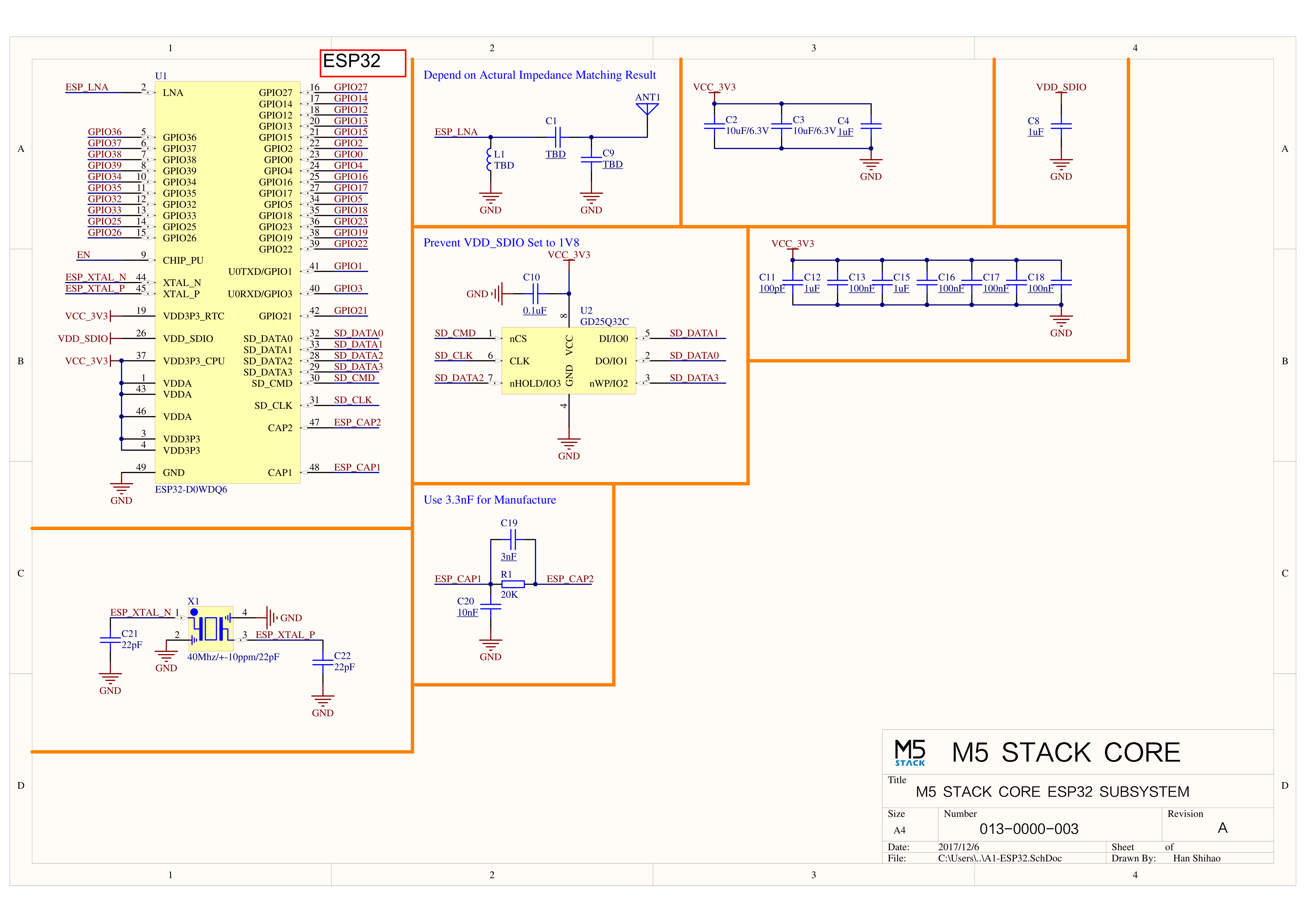
SoC
ESP32-D0WDQ6-V3@dual-core processor, 240MHz main frequency
DMIPS
600
SRAM
520KB
Flash
16MB
Wi-Fi
2.4 GHz Wi-Fi
Input Voltage
5V@500mA
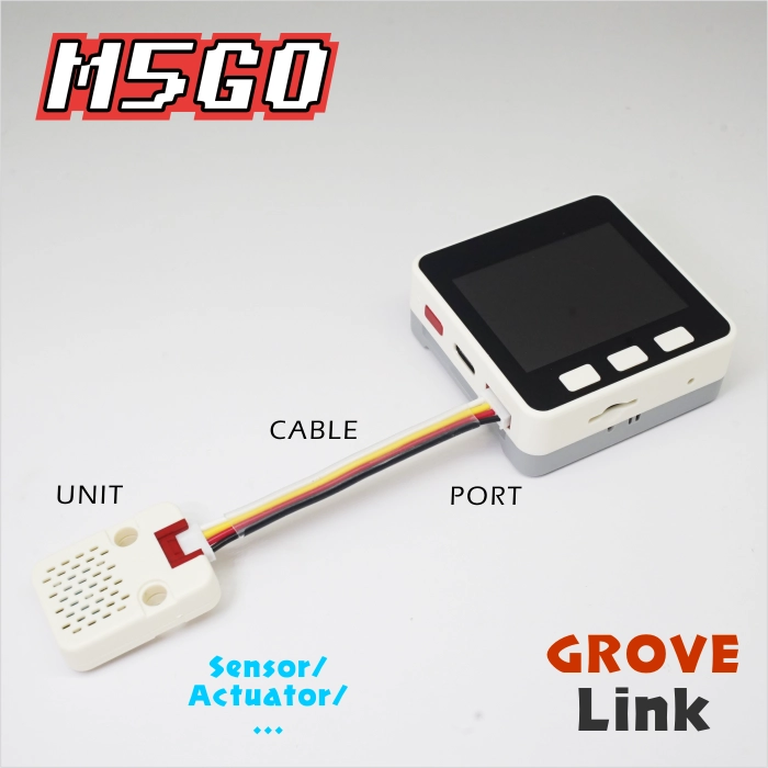
Host Interface
USB Type-C x 1, GROVE (I2C+I/O+UART) x 1
IPS Display
2 inch, 320x240 Colorful TFT LCD, ILI9342C, max brightness 853nit
Buttons
Custom buttons x 3
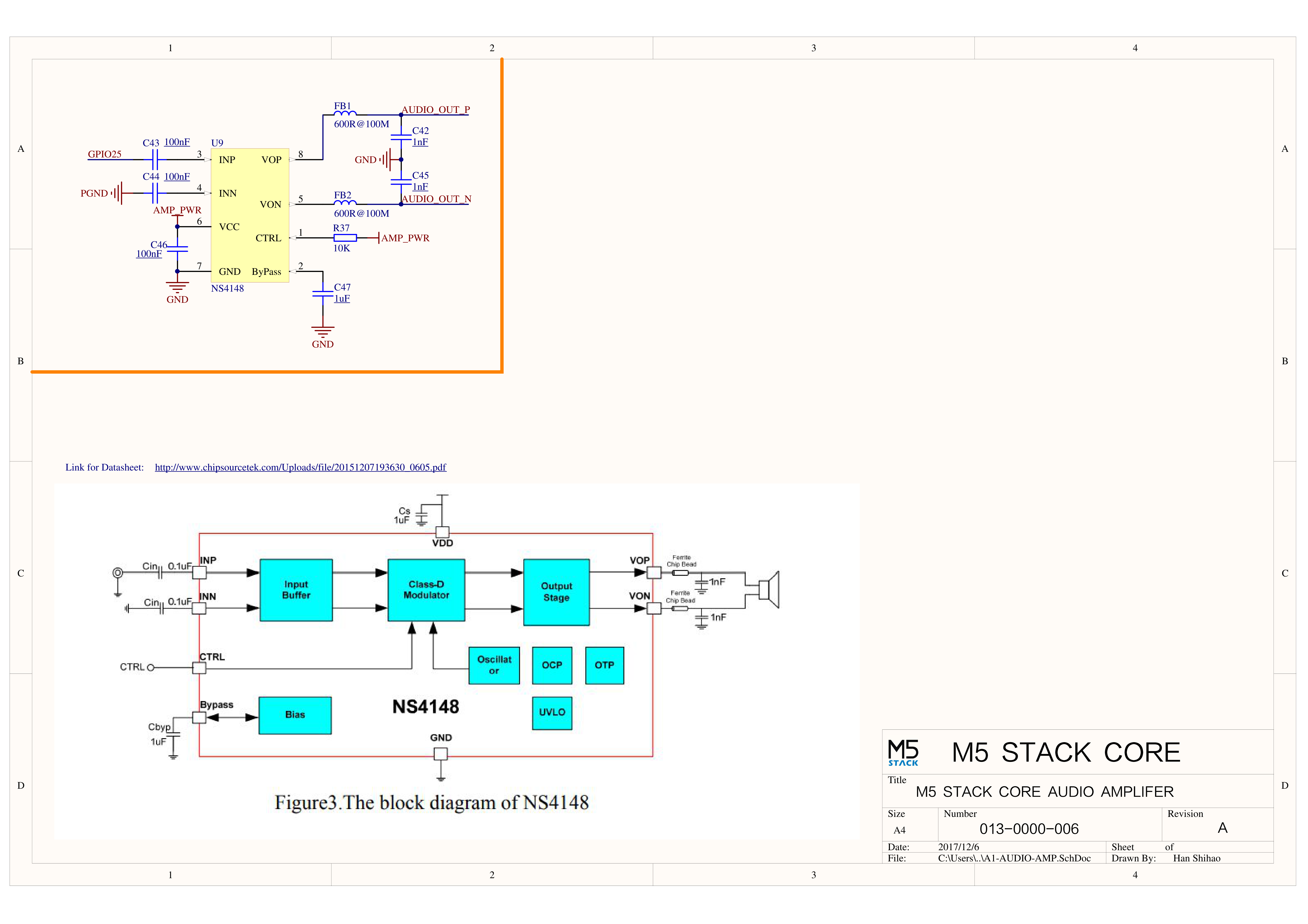
Speaker
1W-0928
Microphone
MEMS Analog BSE3729 Microphone
LED
SK6812 3535 RGB LED x 10
MEMS
BMM150 + MPU6886
Battery
500mAh@3.7V, inside vb
Antenna
2.4G 3D antenna
Operating Temperature
0 ~ 60°C
Case Material
Plastic (PC)
Product Size
54.0 x 54.0 x 21.0mm
Product Weight
56.4g
Package Size
147.0 x 90.0 x 40.0mm
Gross Weight
228.0g
Learn
BMM150 Magnetic Interference
Products with magnets may interfere with the BMM150 magnetic-field sensor, resulting in abnormal readings. When using M5 controllers that contain magnets, remove the magnets and avoid placing the BMM150 sensor near strong magnetic fields.
Power On/Off
Power on: Single-click the left red power button Power off: Double-click the left red power button quickly USB power: By default, the device cannot be powered off while powered by USB
LCD resolution: 320 × 240 TF card supports up to 16 GB
ESP32-D0WDQ6-V3
G23
G19
G18
G14
G27
G33
G32
G4
ILI9342C
MOSI/MISO
/
CLK
CS
DC
RST
BL
TF Card
MOSI
MISO
CLK
CS
Buttons & Speaker
ESP32-D0WDQ6-V3
G39
G38
G37
G25
Button Pins
BUTTON A
BUTTON B
BUTTON C
Speaker
Speaker Pin
GROVE Port A & IP5306
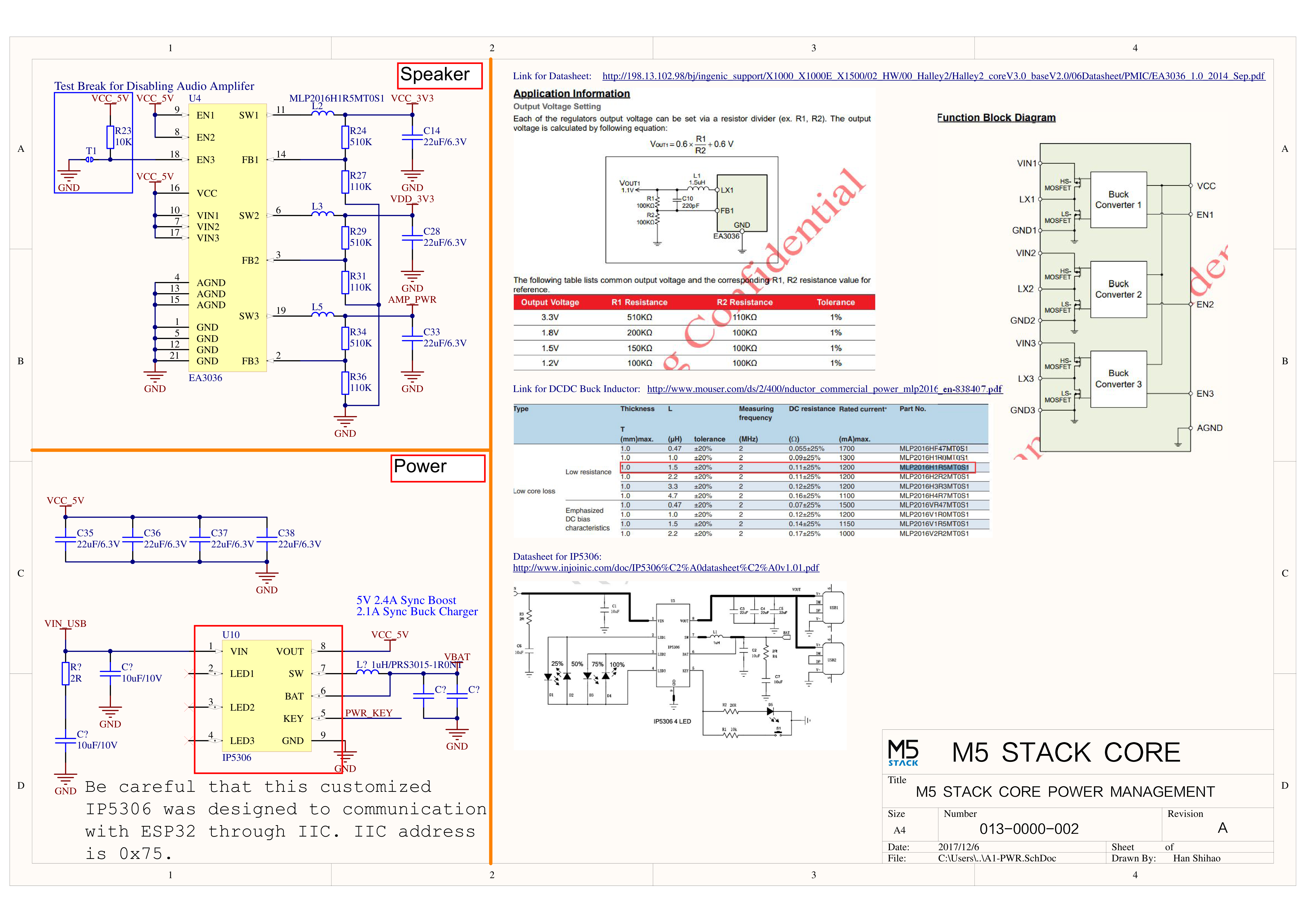
The power-management chip (IP5306) is a customized I2C version with I2C address 0x75. Click here to view the IP5306 register manual.
ESP32-D0WDQ6-V3
G22
G21
5 V
GND
GROVE A
SCL
SDA
5 V
GND
IP5306 (0x75)
SCL
SDA
5 V
GND
IP5306 Charge / Discharge Voltage
Charging
Discharging
0.00 ~ 3.40 V → 0 %
4.20 ~ 4.07 V → 100 %
3.40 ~ 3.61 V → 25 %
4.07 ~ 3.81 V → 75 %
3.61 ~ 3.88 V → 50 %
3.81 ~ 3.55 V → 50 %
3.88 ~ 4.12 V → 75 %
3.55 ~ 3.33 V → 25 %
4.12 V ~ / → 100 %
3.33 ~ 0.00 V → 0 %
MPU6886 Gyroscope & Accelerometer
MPU6886 I2C address 0x68
ESP32-D0WDQ6-V3
G22
G21
5 V
GND
MPU6886 (0x68)
SCL
SDA
5 V
GND
BMM150 3-Axis Magnetometer
BMM150 I2C address 0x10
ESP32-D0WDQ6-V3
G22
G21
5 V
GND
BMM150 (0x10)
SCL
SDA
5 V
GND
M5GO Base Pins
LED Strip & Microphone MIC
ESP32-D0WDQ6-V3
G15
G34
G25
LED Strip
SIG
Microphone MIC
MIC
ESP32 ADC/DAC
ADC1
ADC2
DAC1
DAC2
8 ch
10 ch
2 ch
2 ch
G32-39
G0/2/4/12-15/25-27
G25
G26
HY2.0-4P
HY2.0-4P
Black
Red
Yellow
White
PORT.A
GND
5V
G21
G22
PORT.B
GND
5V
G26
G36
PORT.C
GND
5V
G17
G16
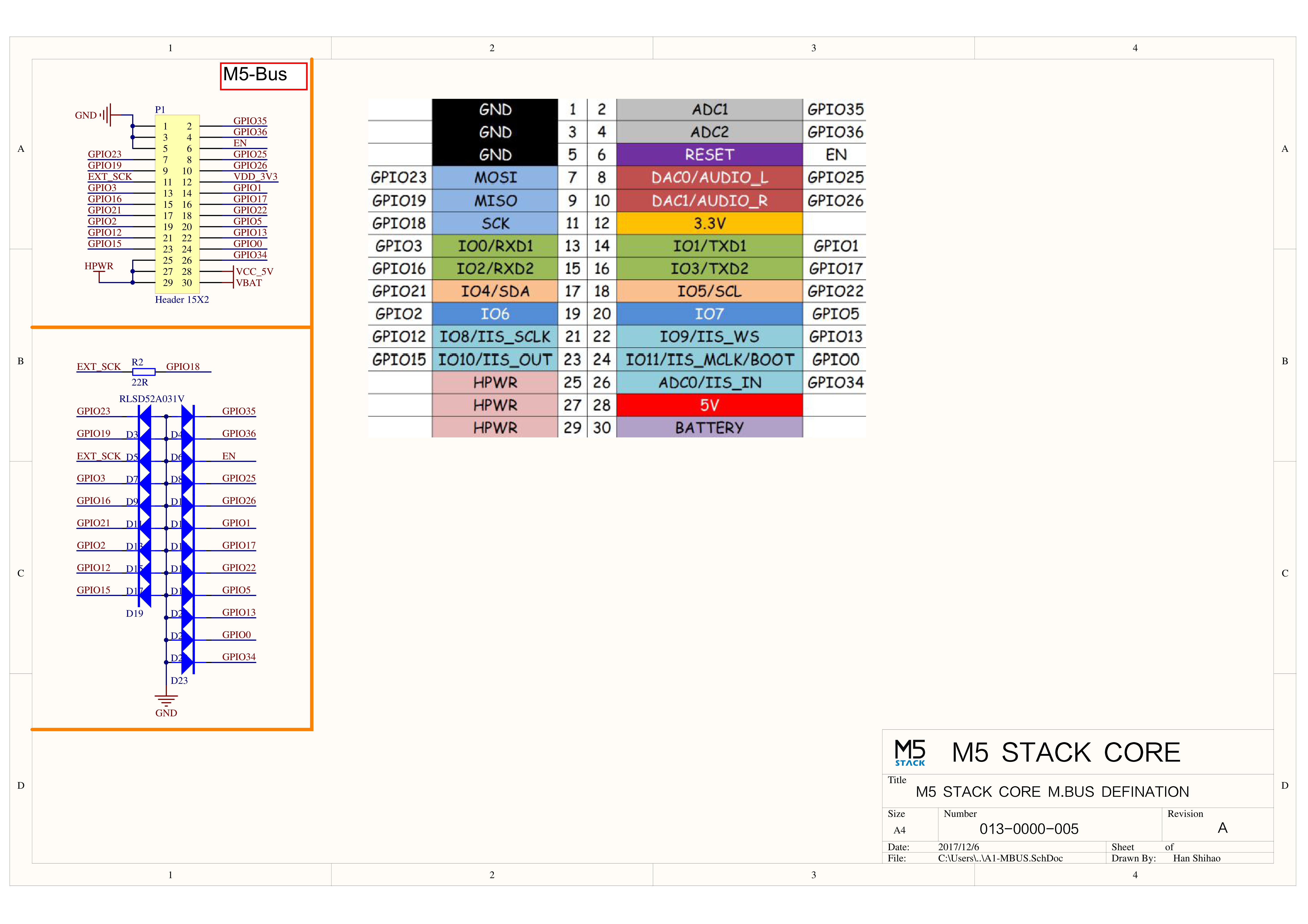
M5-Bus
FUNC
PIN
LEFT
RIGHT
PIN
FUNC
GND
1
2
G35
ADC
GND
3
4
G36
ADC
GND
5
6
RST
EN
MOSI
G23
7
8
G25
DAC/SPK
MISO
G19
9
10
G26
DAC
SCK
G18
11
12
3V3
RXD0
G3
13
14
G1
TXD0
RXD2
G16
15
16
G17
TXD2
Int SDA
G21
17
18
G22
Int SCL
GPIO
G2
19
20
G5
GPIO
I2S_SK
G12
21
22
G13
I2S_WS
I2S_OUT
G15
23
24
G0
I2S_MK
HPWR
25
26
G34
I2S_IN
HPWR
27
28
5V
HPWR
29
30
BAT
When using the RGB LED on G15, it is recommended to initialize the pin with pinMode(15, OUTPUT_OPEN_DRAIN); For more information on pin assignment and remapping, please refer to the ESP32 datasheet.
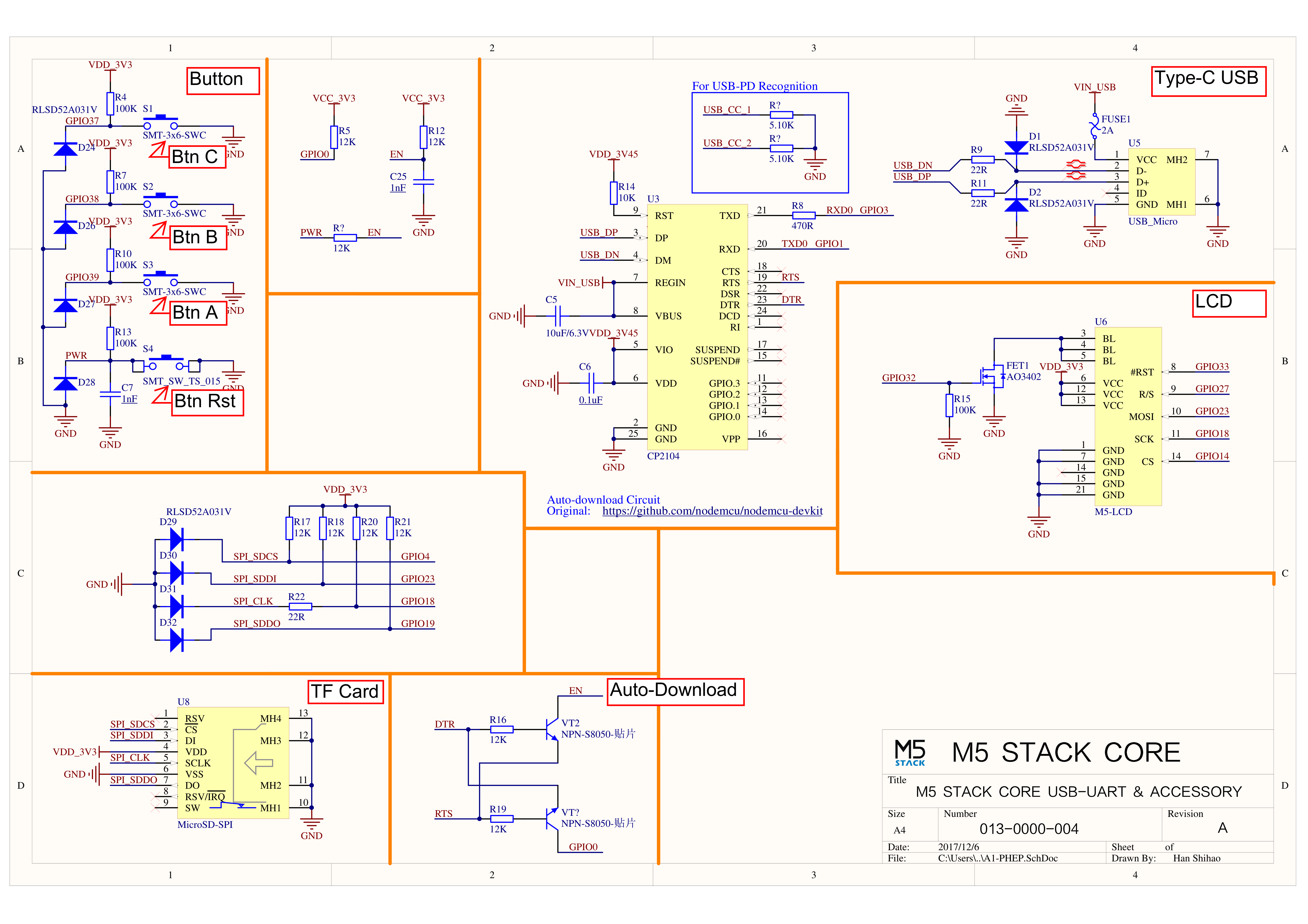
Click the links below to download the driver package that matches your operating system. Two driver chip versions exist: CP210X (for CP2104) and CP34X (for CH9102). After extracting the archive, choose the installer that matches your OS bitness. (If you are unsure which USB chip your device uses, you can install both drivers. CH9102_VCP_SER_MacOS v1.7 may report an error during installation, but the driver is actually installed—just ignore the warning.)
EasyLoader is a lightweight and fast flashing tool that comes with a demo program for this product. By following a few simple steps, you can burn the demo to the controller and verify various functions.
The UIFlow firmware is flashed with a built-in demo that tests the accelerometer, LED bar, microphone, buttons, and some external sensors. The firmware can be used with the UIFlow block-based programming environment.
Product Comparison
To compare information on the controller series products, you can visit the Product Selection Table, check the target products, and get the comparison results. The selection table covers key information such as core parameters and functional features, and supports comparison of multiple products simultaneously.
Version Change
Release Date
Product Changes
Note
2020.6
ENV Unit in the kit changed to Unit ENV-II
/
2019.11
Battery capacity changed from 600mAh to 500mAh
/
2019.7
TN screen changed to IPS screen
Please upgrade your M5Stack library to the latest version (v0.2.8 or above) to solve the screen color inversion problem.
2019.6
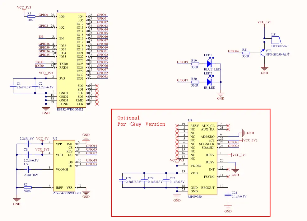
MPU9250 changed to MPU6886+BMM150
/
2018.4
First release
/
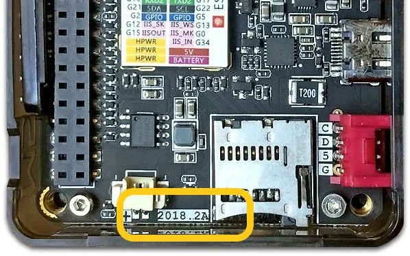
Note
Devices with 2018.2A PCB version do not support C2C (Type-C to Type-C) connection or PD power supply.