
StickC-Plus
SKU:K016-P
Description
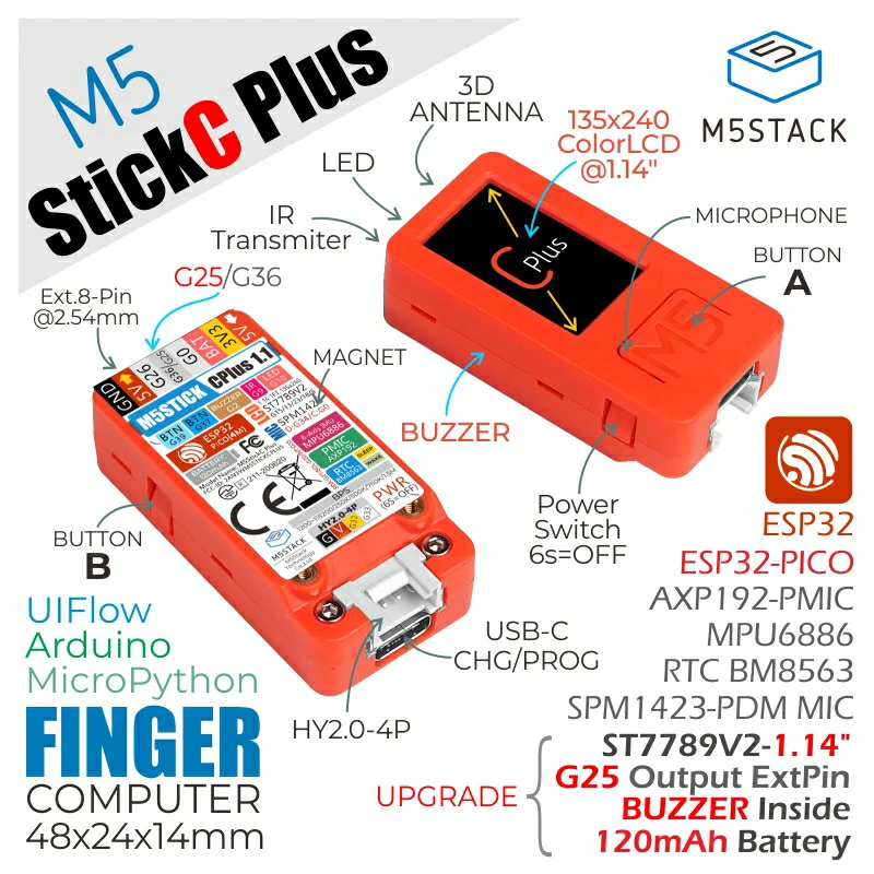
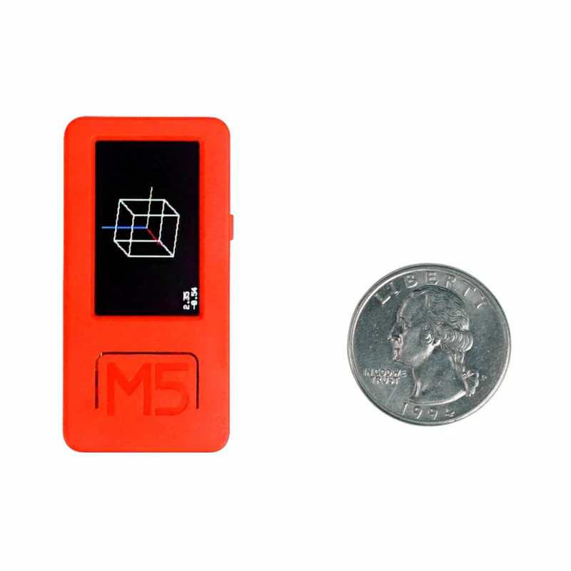
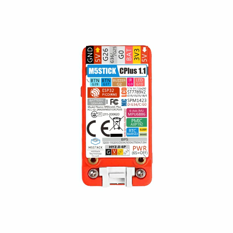
StickC-Plus is the large-screen version of the M5StickC. Its main controller uses the ESP32-PICO-D4 module, which supports Wi-Fi. Inside its compact body, it integrates rich hardware resources such as infrared, RTC, microphone, LED, IMU, buttons, buzzer, PMU, and more. While retaining the original functions of the M5StickC, it adds a passive buzzer. Additionally, the screen size has been upgraded to 1.14 inches, with a resolution of 135 x 240 TFT, increasing the display area by 18.7% compared to the previous 0.96-inch screen. The battery capacity is 120mAh, and the interface supports HAT and Unit series products.
This compact and exquisite development tool can unleash unlimited creative potential. StickC-Plus can help quickly build IoT product prototypes, greatly simplifying the entire development process. Even for beginners who are just starting to learn programming, it can be used to create interesting applications and apply them to real-life scenarios.
Tutorial


Features
- Based on ESP32 development, supports Wi-Fi
- Built-in 3-axis accelerometer and 3-axis gyroscope
- Built-in Red LED
- Integrated infrared transmitter
- Built-in RTC
- Integrated microphone
- User button, LCD (1.14 inch), power/reset button
- 120 mAh lithium battery
- Expansion interface
- Integrated passive buzzer
- Wearable & mountable
- Development Platform
- UiFlow1
- UiFlow2
- Arduino IDE
- ESP-IDF
- PlatformIO
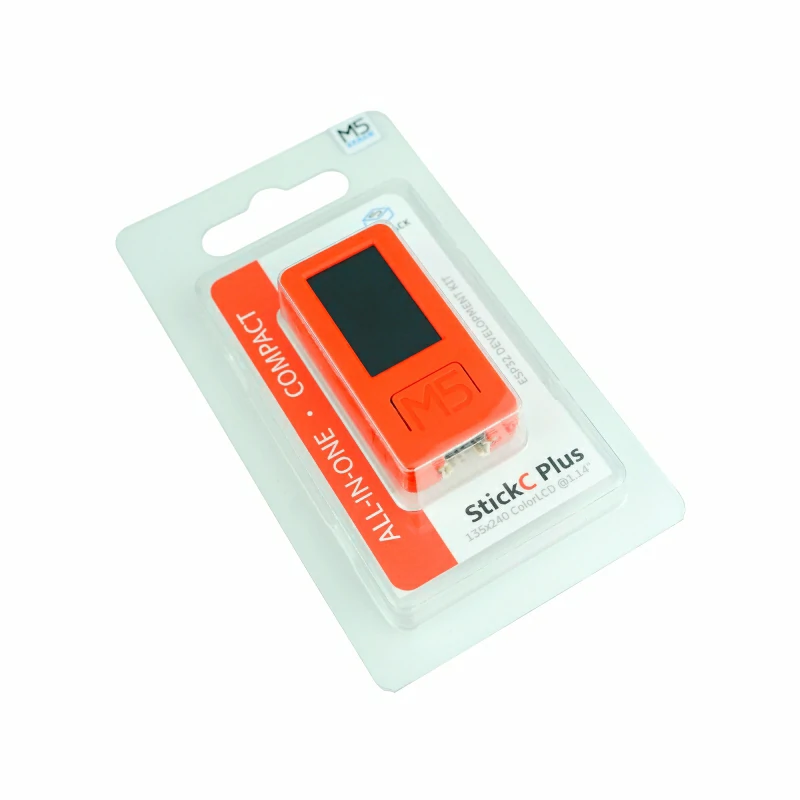
Includes
- 1 x StickC-Plus
Applications
- Wearable devices
- IoT controllers
- STEM education
- DIY projects
- Smart home devices
Specifications
| Specifications | Parameter |
|---|---|
| SoC | ESP32-PICO-D4 @ Xtensa® 32-bit LX6 dual-core processor, clock frequency up to 240MHz |
| Flash | 4MB |
| Wi-Fi | 2.4 GHz Wi-Fi |
| DMIPS | 600 |
| SRAM | 520KB |
| Input Voltage | 5V@500mA |
| Interface | USB Type-C x 1, GROVE (I2C+I/O+UART) x 1 |
| LCD Screen | 1.14 inch, 135 x 240 Colorful TFT LCD, ST7789v2 |
| Microphone | SPM1423 |
| Button | Custom Button x 2 |
| LED | Red LED x 1 |
| RTC | BM8563 |
| PMU | AXP192 |
| Buzzer | Onboard Buzzer |
| IR | Infrared Transmission |
| MEMS | MPU6886 |
| Antenna | 2.4G 3D Antenna |
| External Pins | G0, G25/G26, G36, G32, G33 |
| Battery | 120mAh@3.7V, inside vb |
| Operating Temperature | 0 ~ 60°C |
| Shell Material | Plastic (PC) |
| Product Size | 48.0 x 24.0 x 13.5mm |
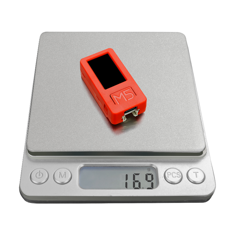
| Product Weight | 16.9g |
| Package Size | 104.4 x 65.0 x 18.0mm |
| Gross Weight | 24.1g |
Learn
Power On/Off Operations
- Power On / Reset: Press the power button once
- Power Off: Press and hold the power button
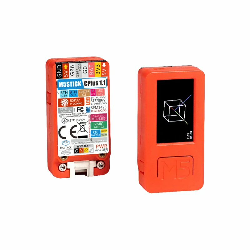
IMU Triaxial Direction Schematic Diagram
Schematics
PinMap
Red LED & IR Transmitter & Button & Buzzer
| ESP32-PICO-D4 | G10 | G9 | G37 | G39 | G2 |
|---|---|---|---|---|---|
| Red LED | LED Pin | ||||
| IR Transmitter | IR Pin | ||||
| Button A | Button Pin | ||||
| Button B | Button Pin | ||||
| Passive Buzzer | Buzzer Pin |
Color TFT Screen
Driver Chip: ST7789v2
Resolution: 135 x 240
| ESP32-PICO-D4 | G15 | G13 | G23 | G18 | G5 |
|---|---|---|---|---|---|
| TFT Screen | TFT_MOSI | TFT_CLK | TFT_DC | TFT_RST | TFT_CS |
Microphone MIC (SPM1423)
| ESP32-PICO-D4 | G0 | G34 |
|---|---|---|
| Microphone MIC | CLK | DATA |
6-Axis IMU (MPU6886) & Power Management Chip (AXP192)
| ESP32-PICO-D4 | G22 | G21 |
|---|---|---|
| 6-Axis IMU | SCL | SDA |
| Power Management Chip | SCL | SDA |
Power Management Chip (AXP192)
| Microphone | RTC | TFT Backlight | TFT IC | ESP32/3.3V MPU6886 | 5V GROVE |
|---|---|---|---|---|---|
| LDOio0 | LDO1 | LDO2 | LDO3 | DC-DC1 | IPSOUT |
Power Switch
| APX192 | PWRON |
|---|---|
| Power Switch | pwr_key |
HY2.0-4P
| HY2.0-4P | Black | Red | Yellow | White |
|---|---|---|---|---|
| PORT.CUSTOM | GND | 5V | G32 | G33 |
Power Structure Diagram
Model Size
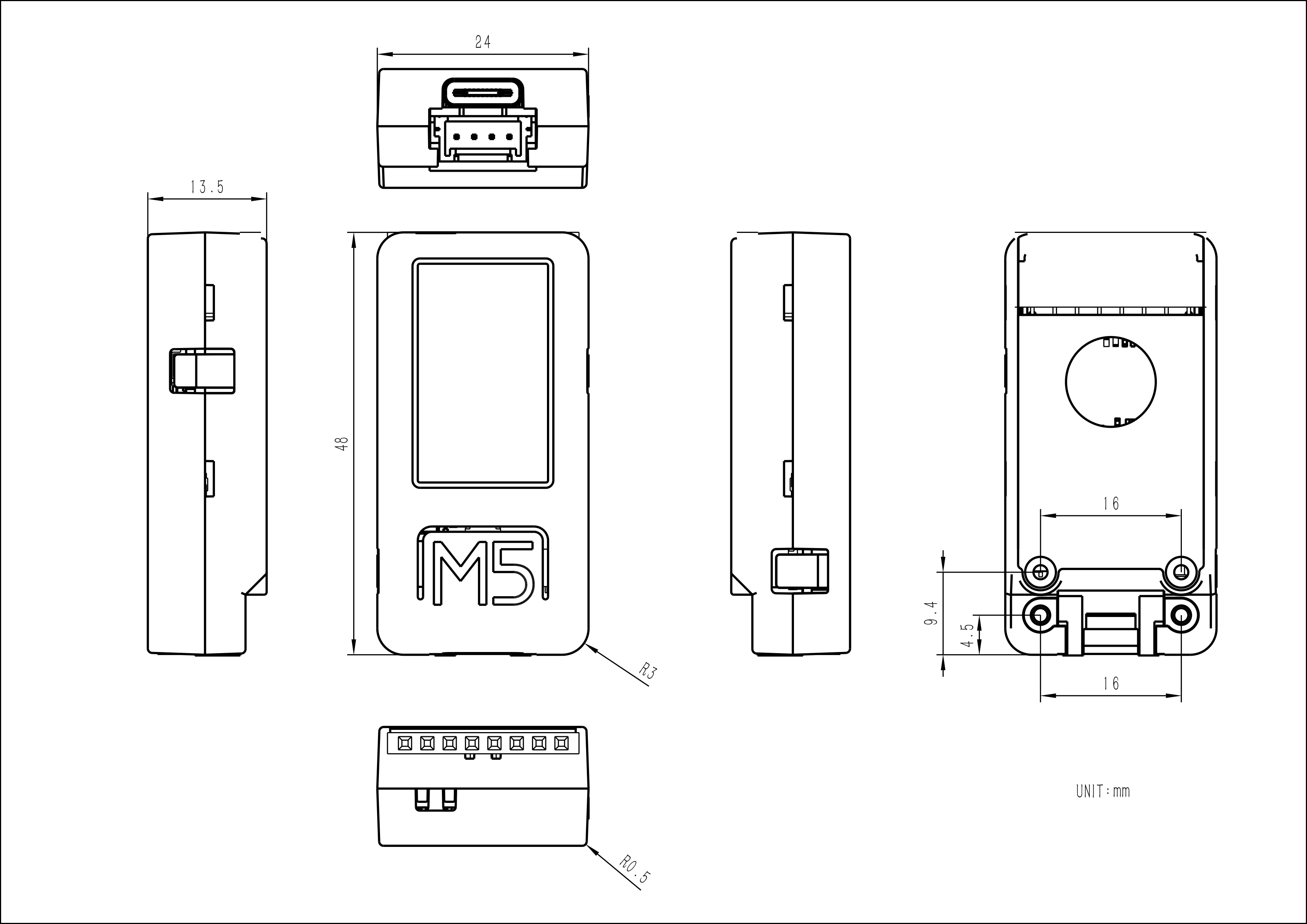
Structure
Datasheets
Softwares
Arduino
UiFlow1
UiFlow2
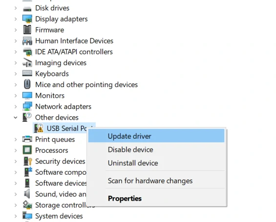
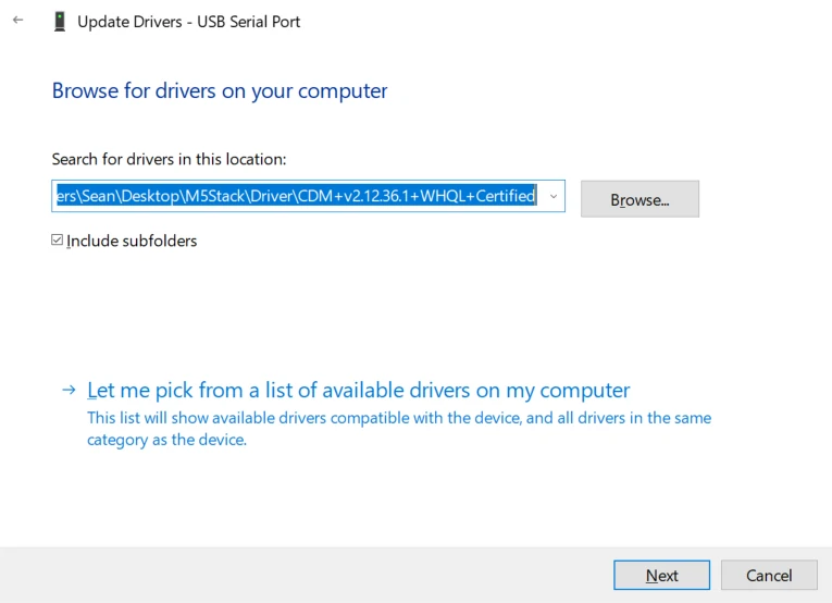
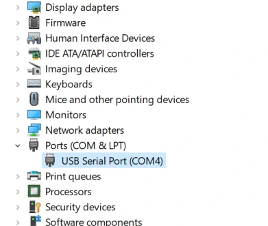
USB Driver
Connect the device to the PC and install the FTDI driver via Device Manager. Taking Windows 10 as an example, download the driver that matches your operating system, unzip it, and install it through Device Manager. (Note: In certain system environments, the driver needs to be installed twice before it becomes effective. Unrecognized device names are usually M5Stack or USB Serial. On Windows, it is recommended to install directly through Device Manager (custom update) using the driver files; the executable installer may not work properly). Click here to download the FTDI driver
Others
Note:
StickC-Plus supported baud rates: 1200 ~115200, 250K, 500K, 750K, 1500K
G36/G25 share the same port. When using one pin, set the other pin to floating input.
- For example, to use the G36 pin as an ADC input, configure the G25 pin as floating.
The input range of VBUS_VIN and VBUS_USB is limited to 4.8-5.5V. When powered by VBUS, the AXP192 power management will charge the internal battery.
setup()
{
   M5.begin();
   pinMode(36, INPUT);
   gpio_pulldown_dis(GPIO_NUM_25);
   gpio_pullup_dis(GPIO_NUM_25);
}Easyloader
| Easyloader | Download Link | Remarks |
|---|---|---|
| StickC-Plus Firmware Easyloader | download | / |
Video
Product Comparison
To compare information on the Stick series products, you can visit the Product Selection Table, check the target products, and get the comparison results. The selection table covers key information such as core parameters and functional features, and supports comparison of multiple products simultaneously.
Version Change
| Release Date | Product Changes |
|---|---|
| 2021.12 | Added sleep and wake-up functions; version changed to v1.1 |
| / | First release |