

Stamp-Pico
SKU:C050-B
Description
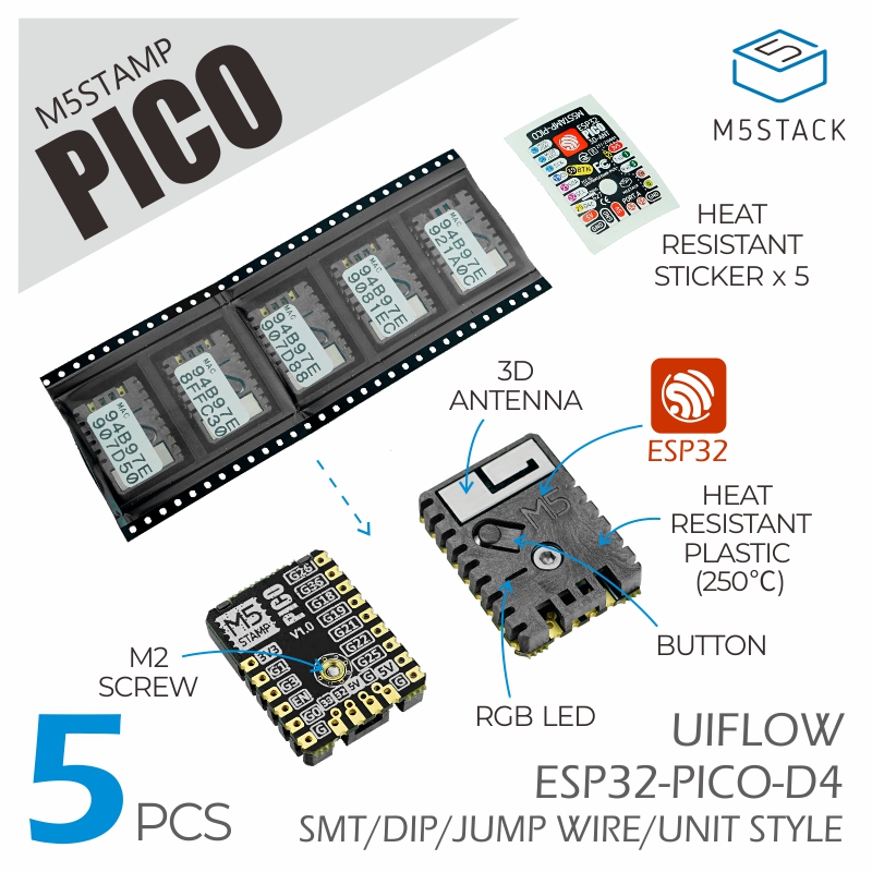
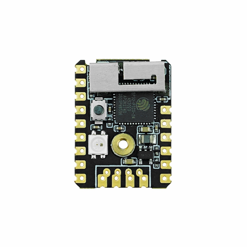
Stamp-Pico is a plug-and-play, cost-effective Wi-Fi minimum core board. Powered by the Espressif ESP32 SoC, it is equipped with two low-power Xtensa® 32-bit LX6 microprocessors running at up to 240 MHz. With its compact size, high performance and low power consumption, it is ideal for space-constrained or battery-powered IoT applications.
Tutorial


Features
- ESP32-PICO-D4 (2.4 GHz Wi-Fi)
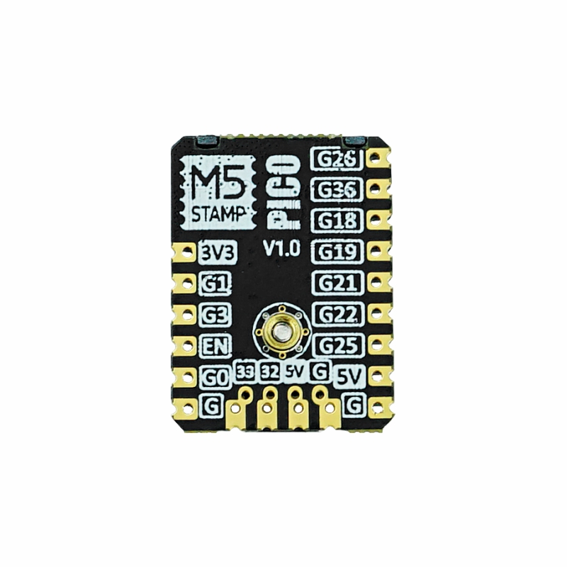
- Multiple I/O breakouts, supporting various mounting methods (SMT, DIP, flying leads)
- Integrated programmable RGB LED and button
- ESP32 minimum system board
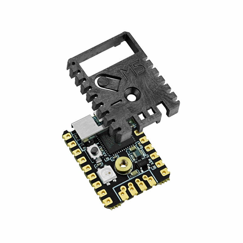
- High-temperature plastic armor for better protection of the 3D antenna and components
- On-board 5V → 3.3V DC/DC circuit, 12 × GPIO, 1 × programmable RGB LED, 1 × button
- Professionally tuned RF circuit for stable and reliable wireless communication
- Development Platform
- UiFlow1
- UiFlow2
- Arduino IDE
- ESP-IDF
- PlatformIO
Includes
- 5 × Stamp-Pico
- 5 × High-temperature Sticker
Applications
- Smart home
- Wearable devices
- Medical equipment
Specifications
| Specification | Parameter |
|---|---|
| SoC | ESP32-PICO-D4@dual-core processor, 240MHz |
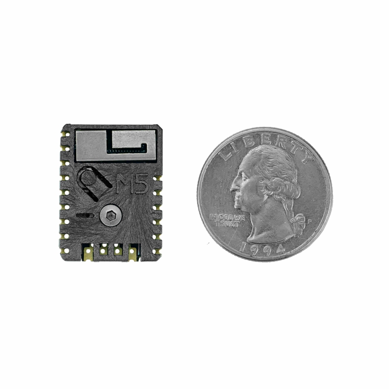
| Package | LGA48 (7×7mm) |
| Flash | 4MB |
| Wi-Fi | 2.4 GHz Wi-Fi |
| DMIPS | 600 |
| SRAM | 520KB |
| Input Voltage | 5V@500mA |
| Power Consumption | Normal standby: 5 V@29 mA / Wi-Fi STA mode: 5 V@60 mA / Classic Bluetooth TX: 5 V@84 mA / DeepSleep: 5 V@0.35 mA |
| Wireless Range | AP mode: 16 m / BLE mode: 110 m / Classic Bluetooth mode: 90 m |
| HMI | 1 × Programmable physical button, 1 × Programmable RGB LED (SK6812) |
| Antenna Type | 2.4 G 3D antenna |
| Wi-Fi | 802.11 b/g/n (up to 150 Mbps with 802.11 n), spectrum range: 2.4 GHz ~ 2.5 GHz |
| Peripheral Interface | ADC, DAC, Touch Sensor, SD/SDIO/MMC Host Controller, SPI, SDIO/SPI Slave Controller, EMAC, Motor PWM, LED PWM, UART, I2C, I2S, IR Remote Controller, GPIO, PCNT |
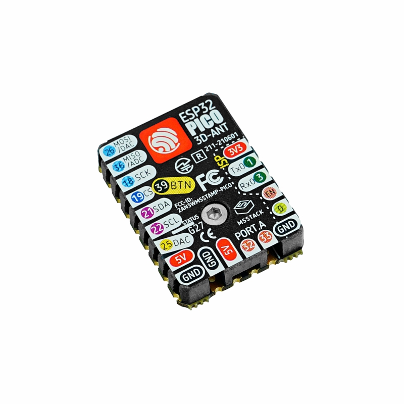
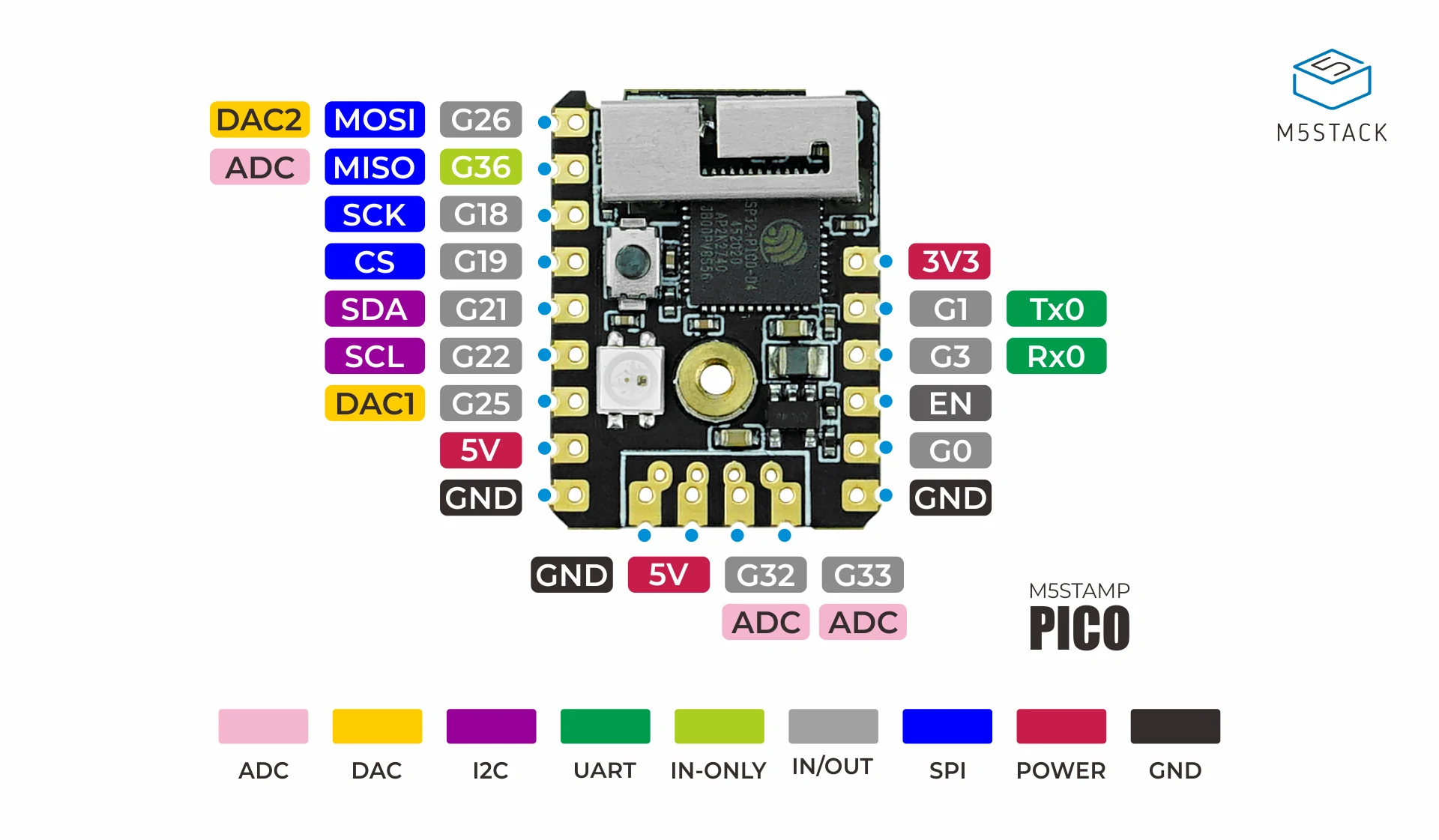
| IO (12 pins) | G0, G1, G3, G26, G36, G18, G19, G21, G22, G25, G32, G33 |
| IO Pitch | 2.54 mm |
| Operating Temp. | 0 ~ 60 °C |
| Mounting Screws | M2 × 4 Countersunk Hex Socket Machine Screws |
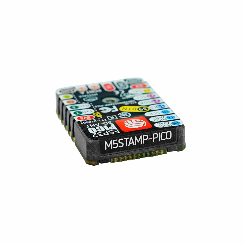
| Product Size | 24.0 × 18.0 × 4.6 mm |
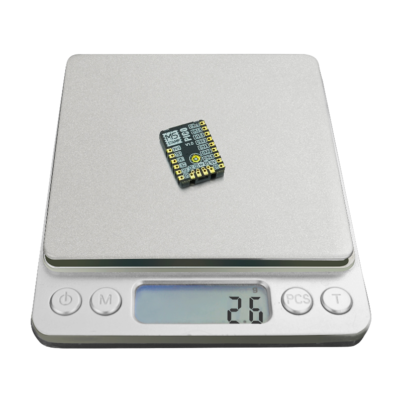
| Product Weight | 13.7 g (5 pcs) |
| Package Size | 138.0 × 93.0 × 5.6 mm |
| Gross Weight | 16.3 g |
Learn
Download Program
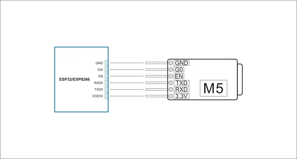
Stamp-Pico adopts an ultra-simplified circuit design and therefore does not include an onboard download circuit. To burn firmware, connect a USB-TTL downloader as shown below.
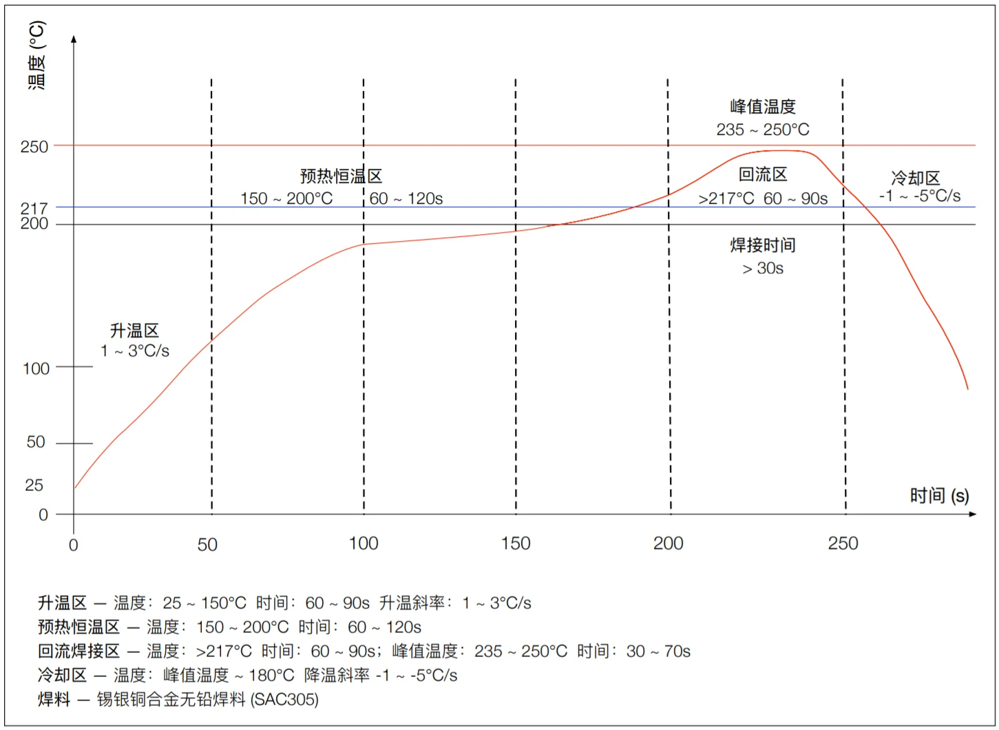
Reflow Soldering Temperature Curve for the Shell
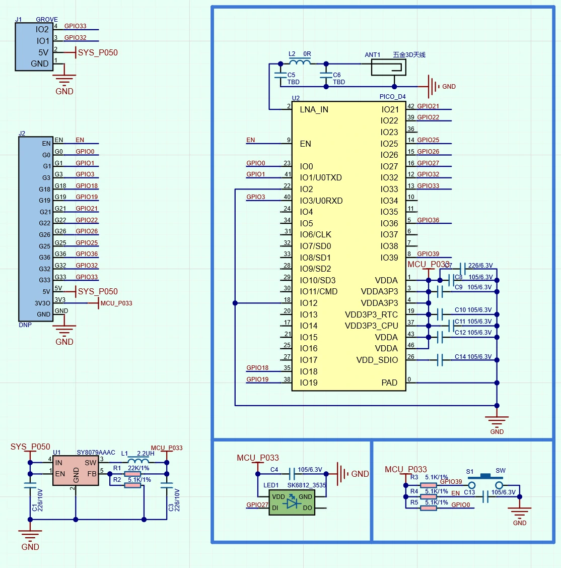
Schematics
PinMap
SK6812, Button
| ESP32-PICO-D4 | G27 | G39 |
|---|---|---|
| SK6812 | DI | / |
| Button | / | SW |
Model Size
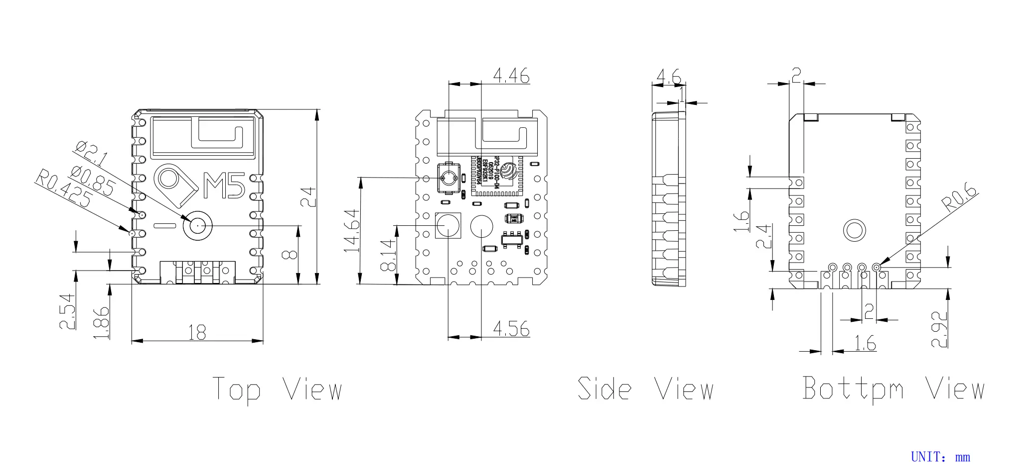

Structure
PCB
Datasheets
Softwares
Arduino
- Stamp-Pico Arduino Quick Start
- Stamp-Pico Button Example
- Stamp-Pico IO Example
- Stamp-Pico LED Example
UiFlow1
UiFlow2
USB Driver
Before flashing, you need to connect a USB-TTL downloader board to the Stamp-Pico according to the silkscreen. Install the corresponding driver for the downloader on your PC.
For the easiest experience, purchase the Stamp-Pico kit with downloader. The cable order is identical to STAMP-PICO, allowing direct plug-in flashing without wiring. M5 currently provides downloaders with two driver chips: CP210X (for CP2104) / CH9102 (for CH9102). After extracting the package, choose the installer matching your OS bitness. (If you are unsure which USB chip your device uses, install both drivers.)
| Driver Name | Applicable Chip | Download Link |
|---|---|---|
| CP210x_VCP_Windows | CP2104 | Download |
| CP210x_VCP_MacOS | CP2104 | Download |
| CP210x_VCP_Linux | CP2104 | Download |
| CH9102_VCP_SER_Windows | CH9102 | Download |
| CH9102_VCP_SER_MacOS v1.7 | CH9102 | Download |
Video
Product Comparison
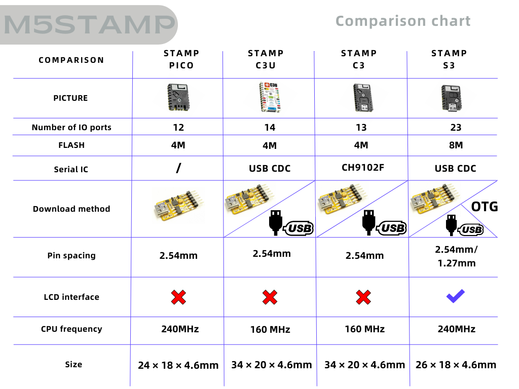
To compare information on the Stamp series products, you can visit the Product Selection Table, check the target products, and get the comparison results. The selection table covers key information such as core parameters and functional features, and supports comparison of multiple products simultaneously.