
Hat CBack Driver
SKU:A100

Description
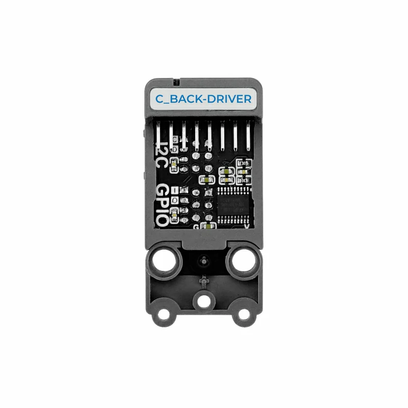
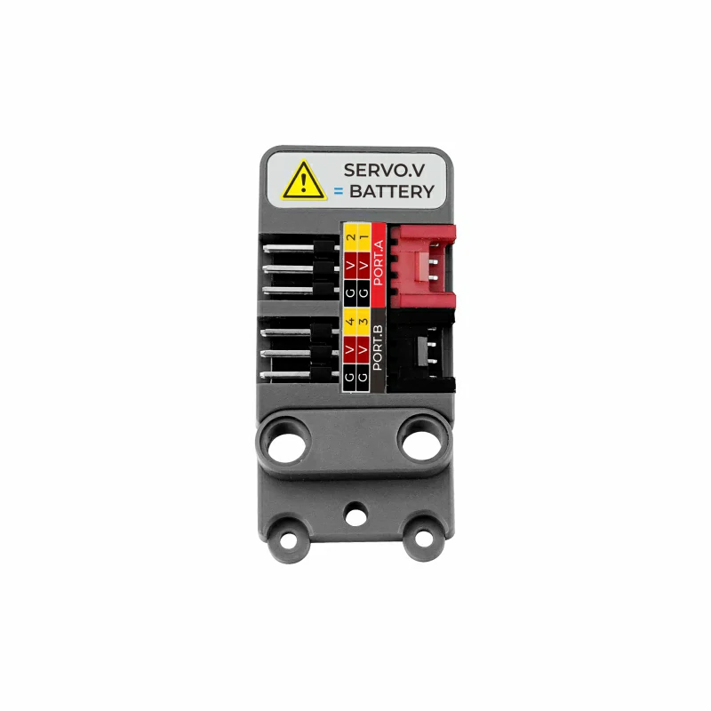
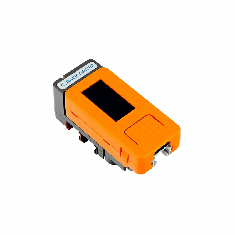
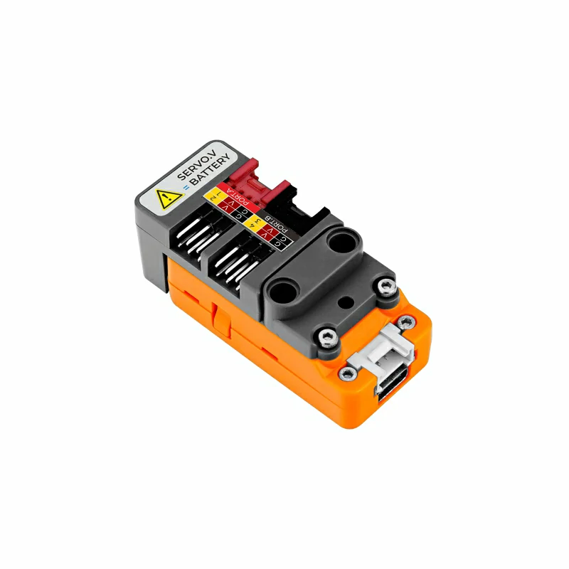
Hat CBack Driver is a servo driver board compatible with M5StickC, using the STM32F030F4P6 control solution and communicating with M5StickC via the I2C interface. It provides 4 sets of PWM servo driving interfaces (the servo's driving power is directly connected to the M5StickC's internal battery, capable of driving general specification servos such as SG90). The module leads out the I2C bus from the top of StickC, and through the STM32, it also provides an additional GPIO interface for general logic level and ADC analog signal input reading. The back is designed with LEGO-compatible holes, allowing users to easily integrate this driver board into LEGO brick structures, suitable for building controllable structures such as servo robotic arms.
Features
- 4 x Servo Drive
- Compatible with C/C Plus
- Interface expansion (GPIO, I2C)
Includes
- 1 x Hat CBack Driver
- 2 x Hexagon Screw M2*5
- 1 x Hex Key L-Shape
- 1 x LEGO Compatible Connector
Applications
- Servo Controller
- Robot Control
Specifications
| Specification | Parameter |
|---|---|
| MCU | STM32F030F4P6 |
| Communication Interface | I2C Communication @0x38 |
| Working Current | 15mA |
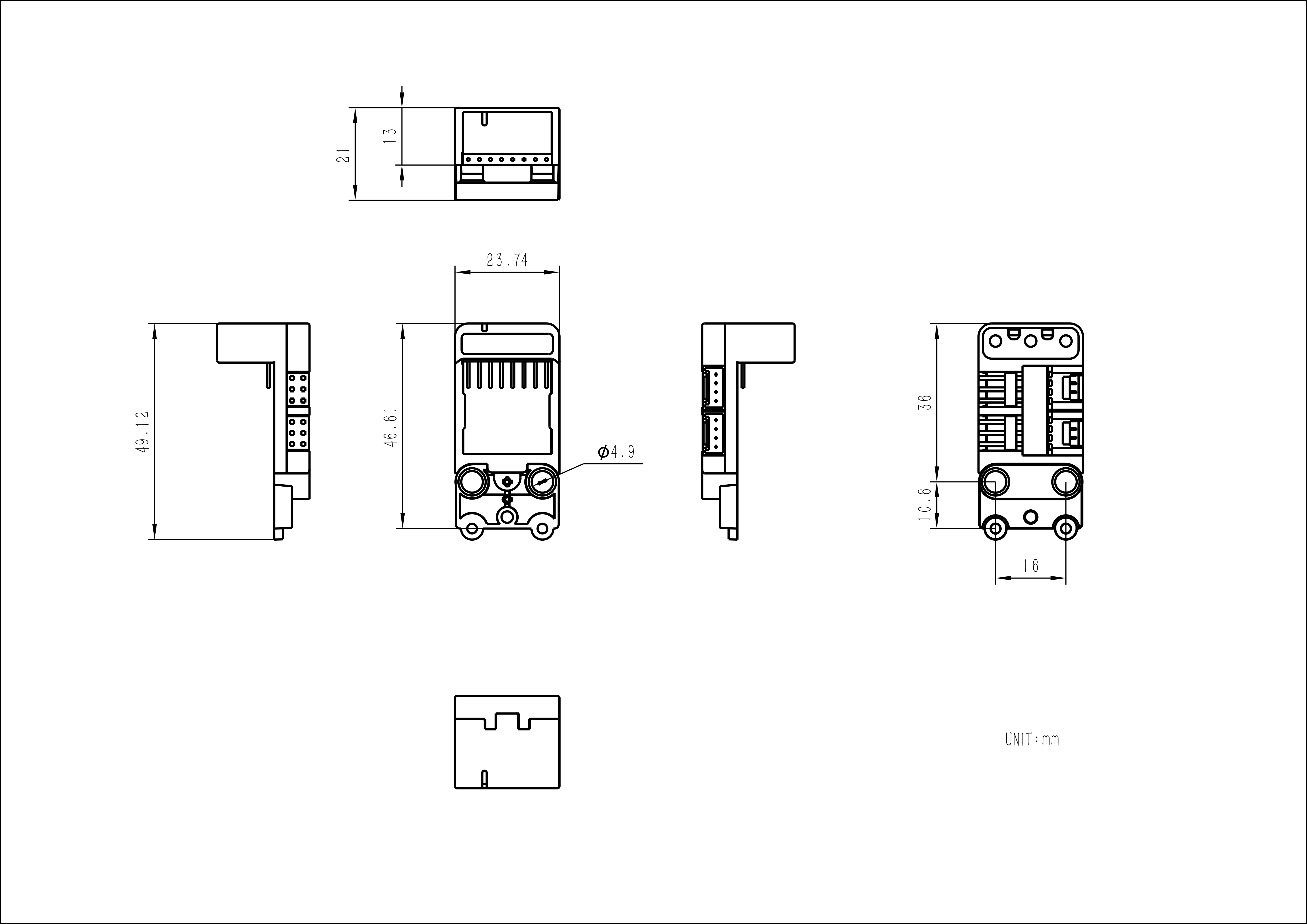
| Product Size | 23.7 x 49.2 x 21.0mm |
| Product Weight | 9.0g |
| Package Size | 138.0 x 93.0 x 22.0mm |
| Gross Weight | 13.5g |
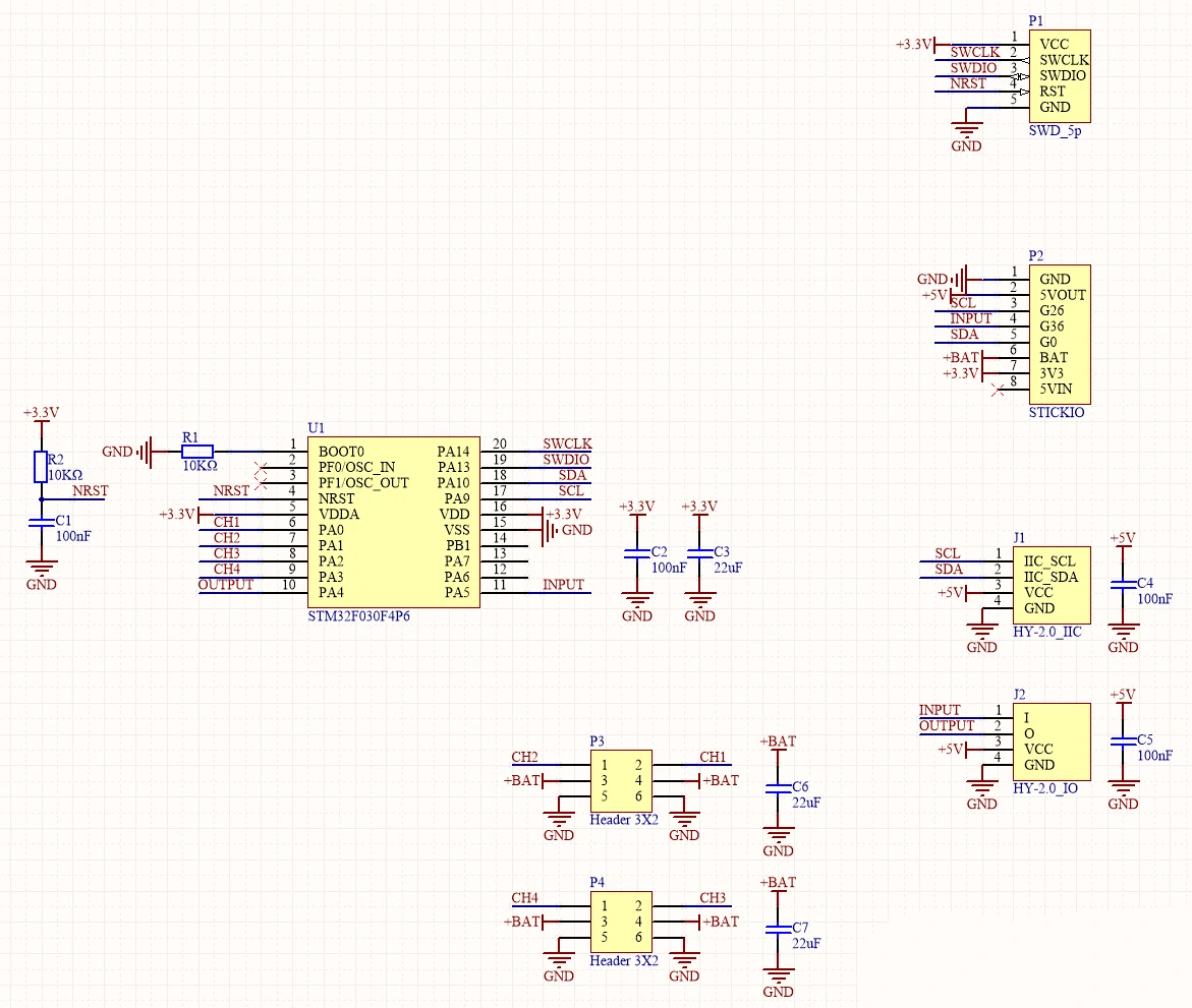
Schematics
PinMap
| M5StickC | G0 | G26 | 3.3V | GND |
|---|---|---|---|---|
| C Back Driver | SDA | SCL | 3.3V | GND |
Model Size
Hat CBack Driver Model Size PDF
Softwares
UiFlow1
Protocol
- Protocol type: I2C
- I2C Address: 0x38
/*------------------------------------------------ -------------------------------------------------- */
| SERVO_ANGLE_REG | 0x00-0x03
| ------------------------------------------------- -----------------------------------------------
| servo_1_reg[0] 0x00 | R/W | SERVO1 Angle value(0~180)
| servo_2_reg[1] 0x01 | R/W | SERVO2 Angle value(0~180)
| servo_3_reg[2] 0x02 | R/W | SERVO3 Angle value(0~180)
| servo_4_reg[3] 0x03 | R/W | SERVO4 Angle value(0~180)
/*------------------------------------------------ -------------------------------------------------- -
/*------------------------------------------------ -------------------------------------------------- */
| SERVO_PULSE_REG | 0x10-0x17
| ------------------------------------------------- -----------------------------------------------
| servo_1_reg[0:1] 0x10-0x11 | R/W | SERVO1 PULSE value(500~2500)
| servo_2_reg[2:3] 0x12-0x13 | R/W | SERVO2 PULSE value(500~2500)
| servo_3_reg[4:5] 0x14-0x15 | R/W | SERVO3 PULSE value(500~2500)
| servo_4_reg[6:7] 0x16-0x17 | R/W | SERVO4 PULSE value(500~2500)
/*------------------------------------------------ -------------------------------------------------- -
/*------------------------------------------------ -------------------------------------------------- */
| PPORTB_ADC_REG | 0x20-0x21
| ------------------------------------------------- -----------------------------------------------
| portb_adc_reg[0:1] 0x20-0x21 | R | PPORTB ADC value(0~4095)
/*------------------------------------------------ -------------------------------------------------- -
/*------------------------------------------------ -------------------------------------------------- */
| PPORTB_OUTPUT_REG | 0x30
| ------------------------------------------------- -----------------------------------------------
| portb_output_reg[0] 0x30 | R | PPORTB Output Digital value(0/1)
/*------------------------------------------------ -------------------------------------------------- -
/*------------------------------------------------ -------------------------------------------------- */
| PPORTB_INPUT_REG | 0x31
| ------------------------------------------------- -----------------------------------------------
| portb_input_reg[0] 0x31 | R | PPORTB Input Digital value(0/1)
/*------------------------------------------------ -------------------------------------------------- -Video
- Making a Four-Wheel Car with Hat CBack Driver