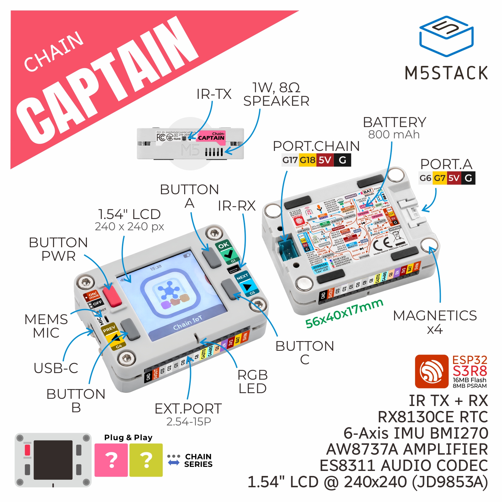
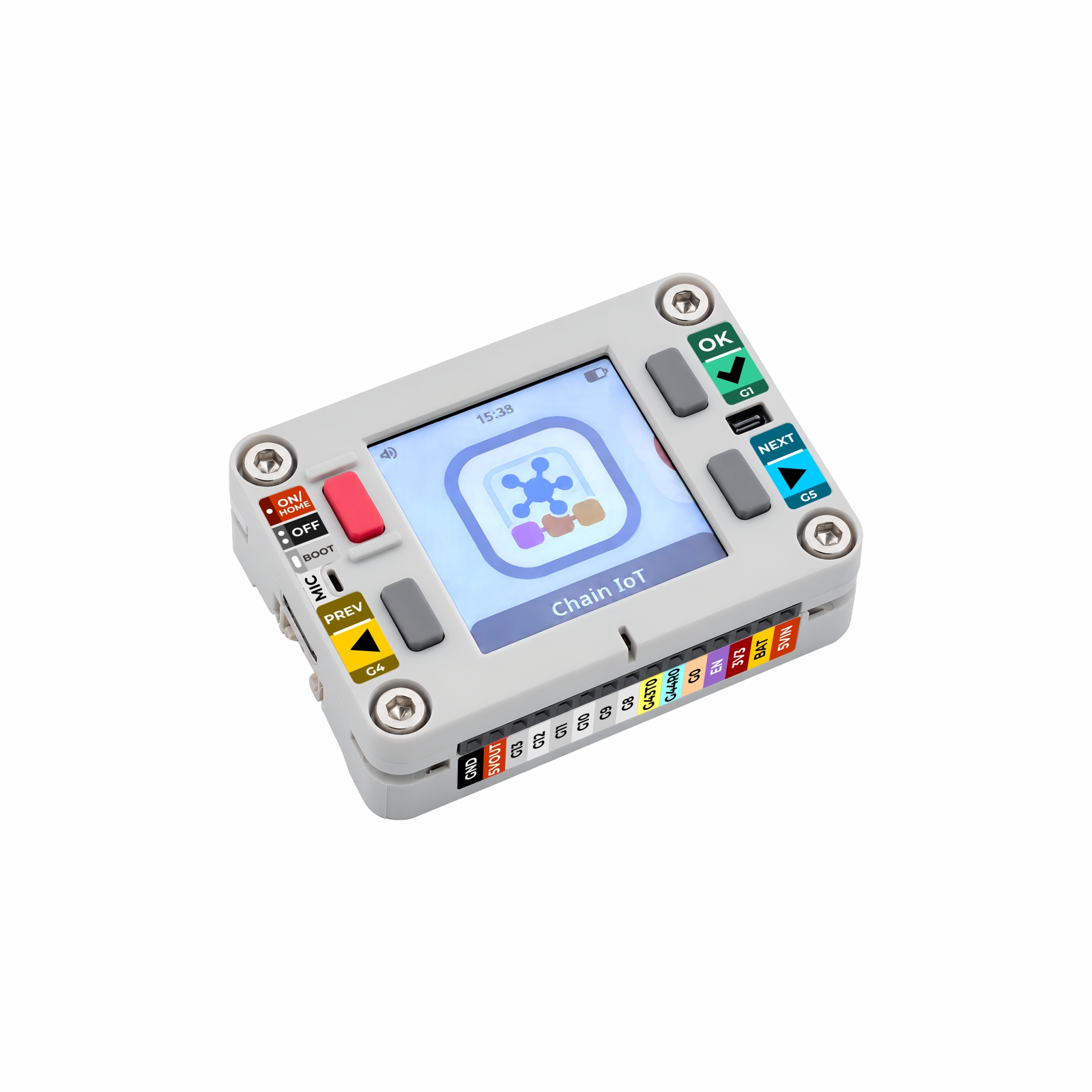
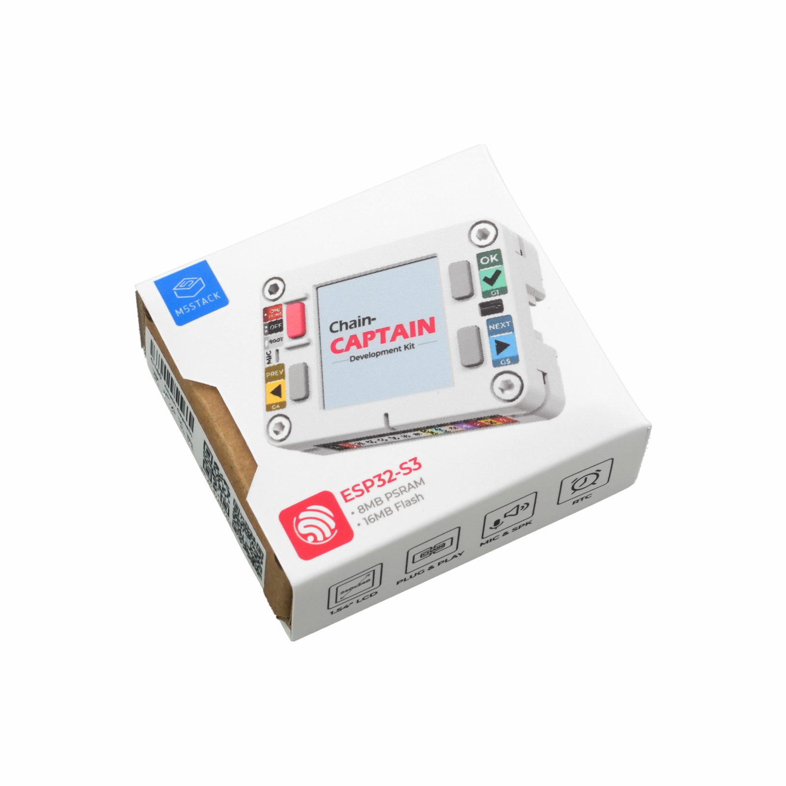
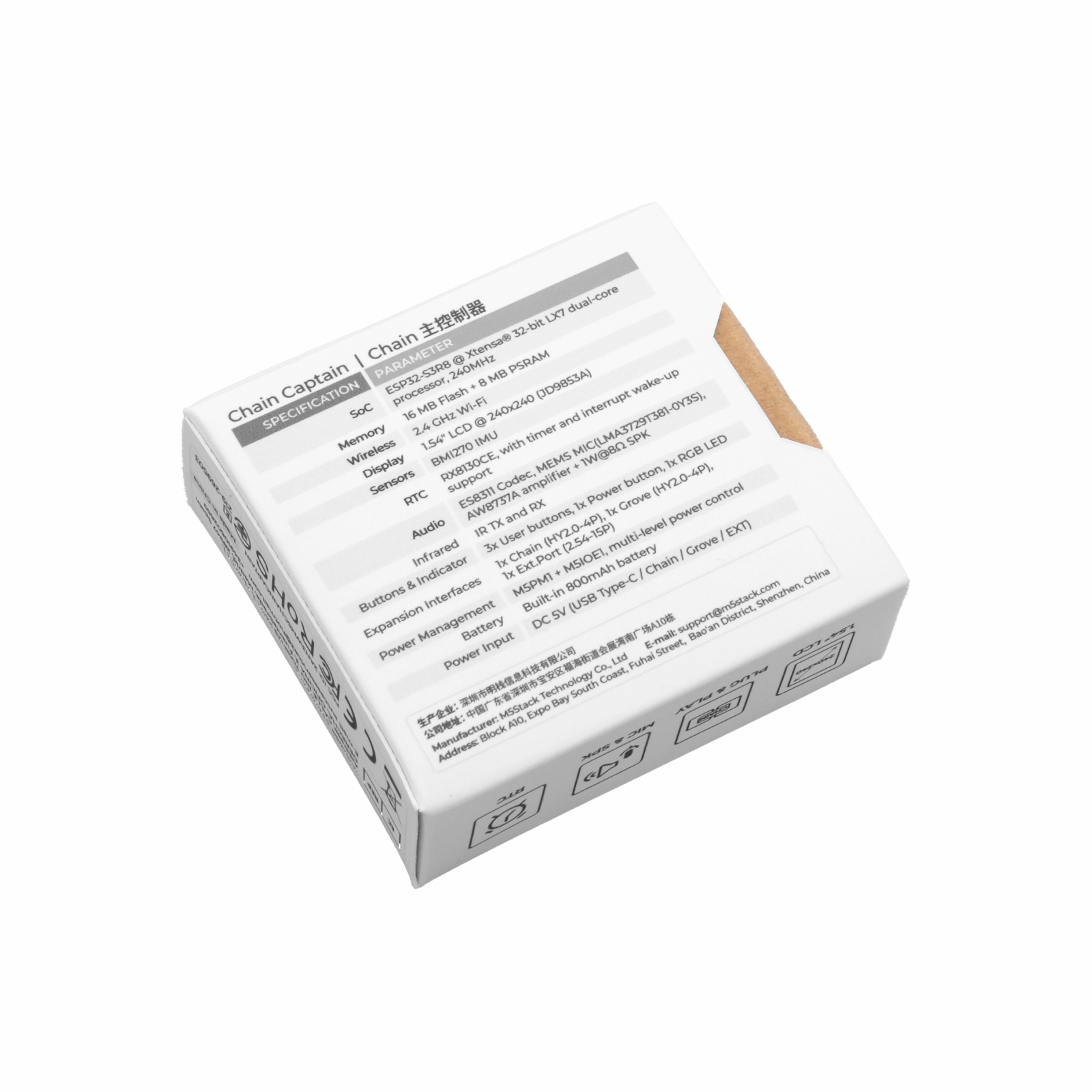
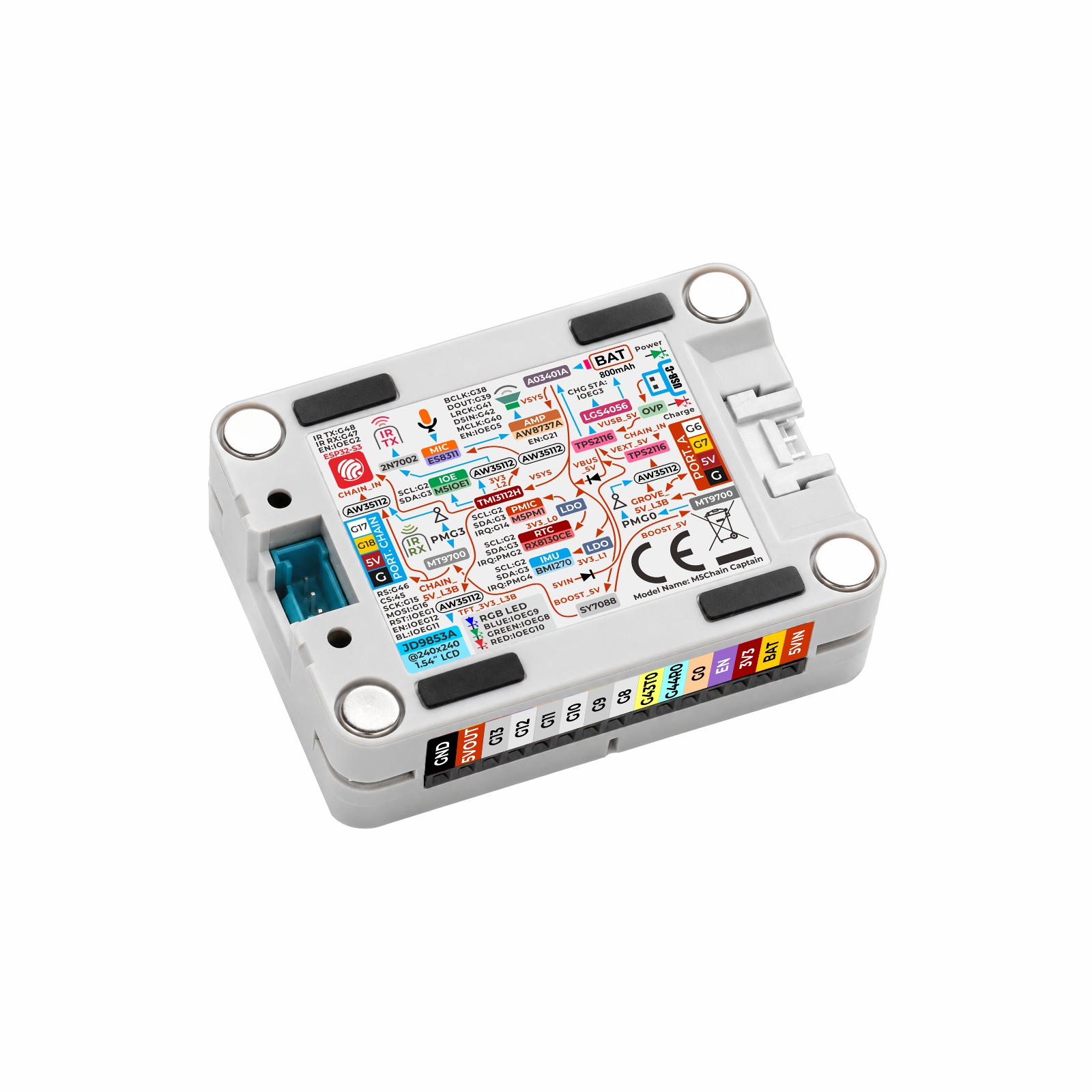
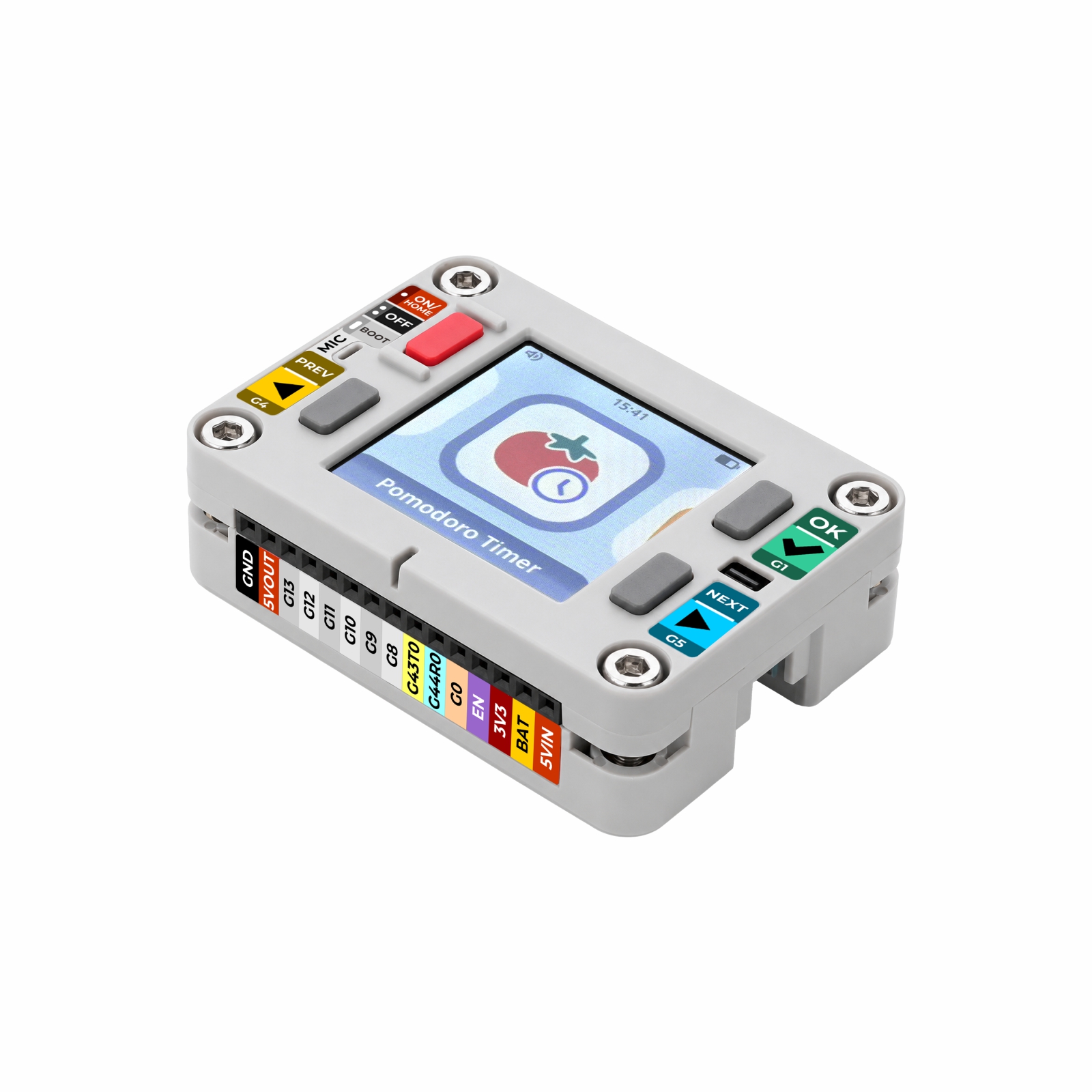
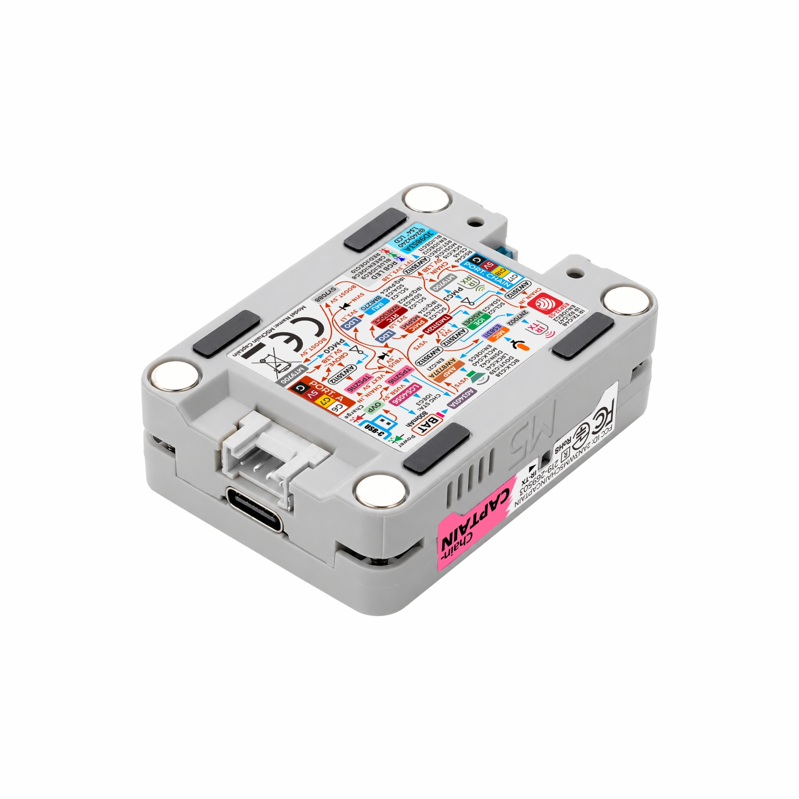
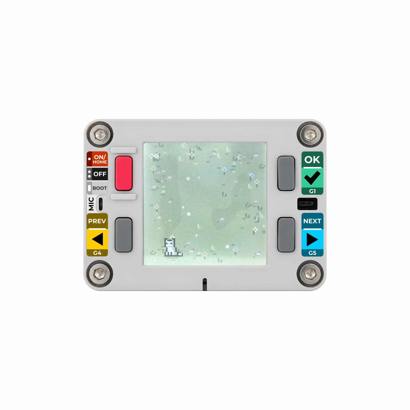
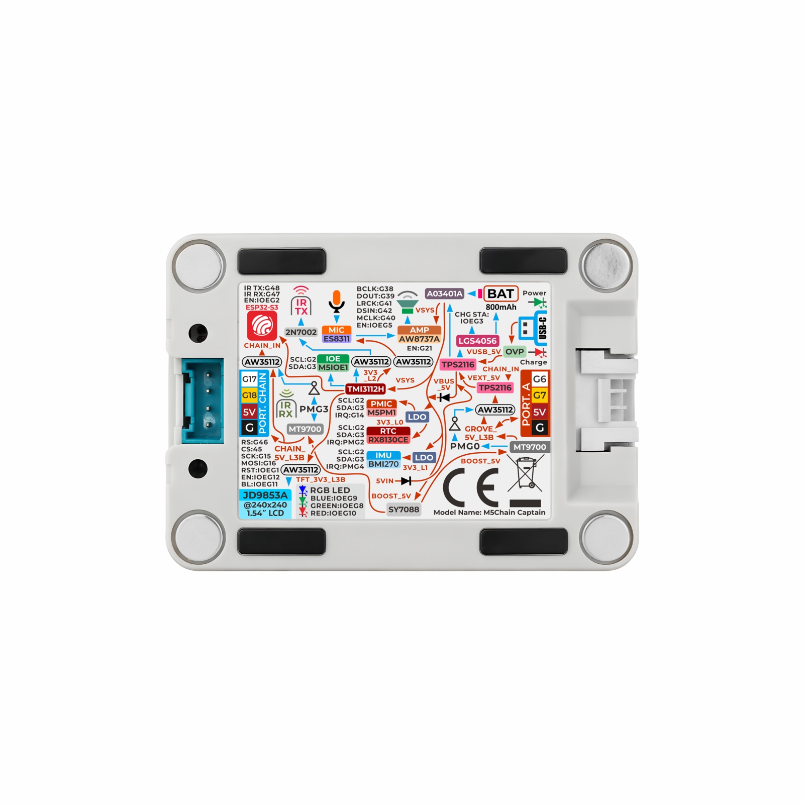
Chain Captain is a multifunctional programmable controller in the M5Stack Chain series. It combines a color display, button controls, audio input and output, motion sensing, and infrared transmission and reception. It is powered by an ESP32-S3R8 with a 240MHz Xtensa® 32-bit LX7 dual-core processor, 16MB Flash, and 8MB PSRAM, and supports 2.4 GHz Wi-Fi.
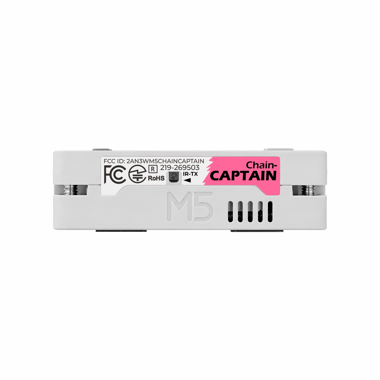
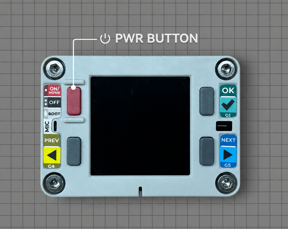
The 1.54-inch 240 x 240 color LCD, three user buttons, power button, and RGB LED provide a graphical interface and status feedback. The audio system combines an ES8311 codec, an analog MEMS microphone, an AW8737A amplifier, and a 1W @ 8Ω speaker for audio capture, playback, and voice interaction. The built-in BMI270 6-axis IMU detects motion and orientation. The RX8130CE real-time clock supports timekeeping, alarms, and interrupt wake-up. The infrared transmitter and receiver enable remote control and communication with other devices.
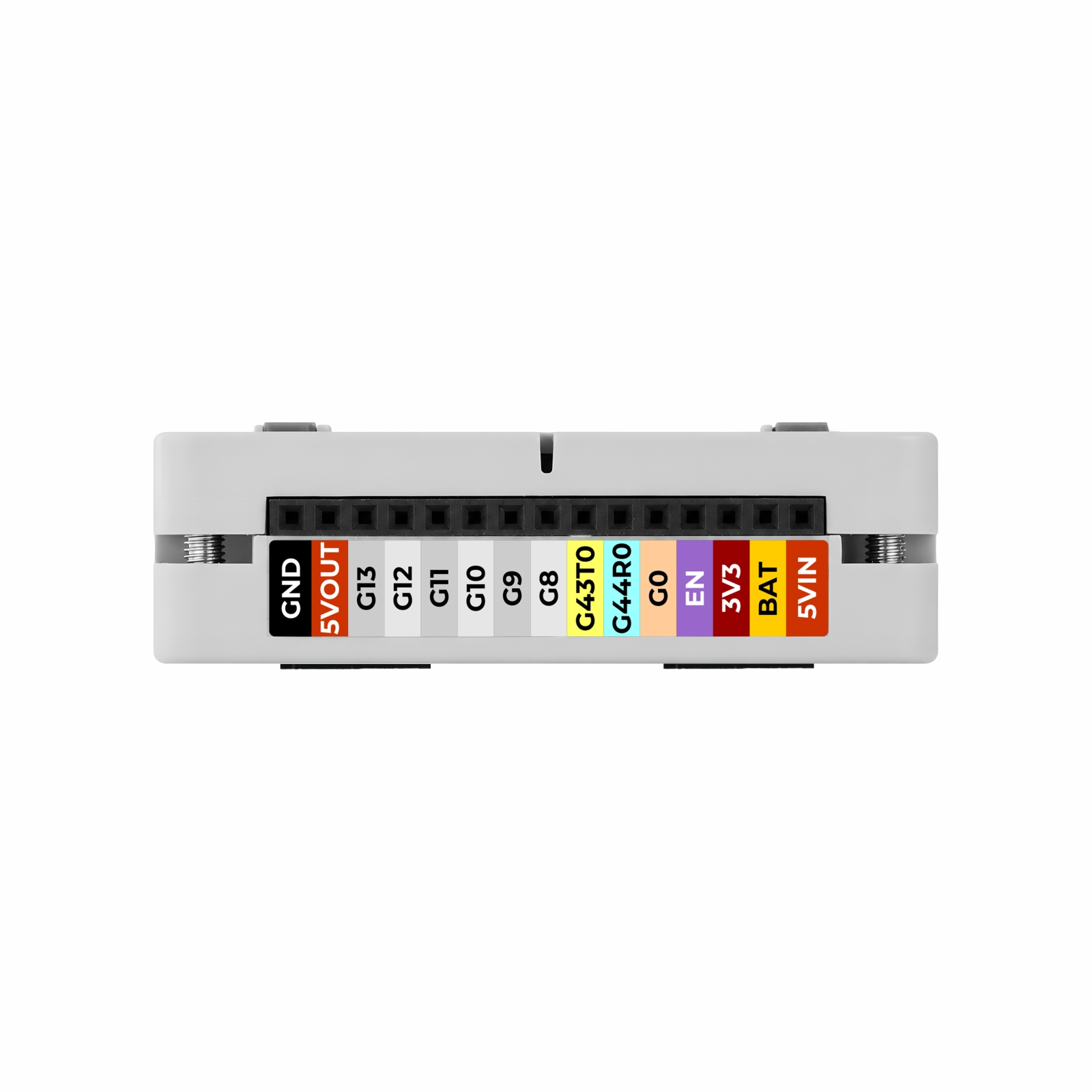
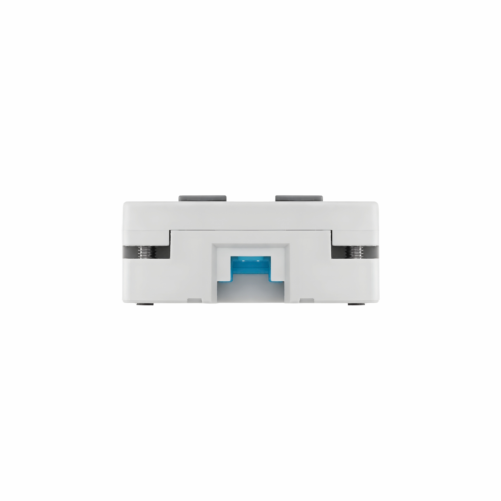
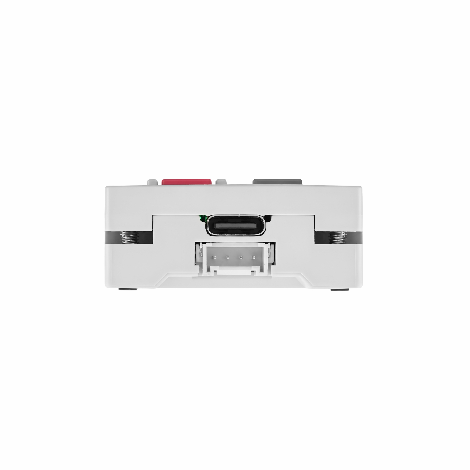
Chain Captain has a built-in 800mAh battery. Its M5PM1 + M5IOE1 multi-level power management system controls power to individual modules and supports standby, deep sleep, and external interrupt wake-up. The device provides one Chain port and one Grove port, both using HY2.0-4P connectors, as well as an Ext.Port (2.54-15P) expansion bus. It supports multiple DC 5V input sources. As a Chain Bus master, it can connect to and control daisy-chained nodes over the Chain port's UART bus, enabling multi-node interactive applications. With its rich interactive features and expansion interfaces, it is suitable for portable control terminals, desktop interaction, smart home controllers, infrared remote control, and sensor data acquisition.
1 x charging indicator (red), 1 x operating status indicator (green), 1 x RGB LED
Power Management
Stamp Timer Power2 (M5PM1) + M5IOE1
Battery
DC 3.7V @ 800mAh
Charging Current
LGS4056HDA battery charger IC, 300mA charging current
Input Power
DC 5V (USB Type-C / Grove / Chain / Ext.Port (2.54-15P) 5VIN)
Interfaces
1 x USB Type-C, 1 x Chain (HY2.0-4P), 1 x Grove (HY2.0-4P), 1 x Ext.Port (2.54-15P)
Power Consumption
Standby: 4.2V@14.39μA Full load: 4.2V@301.71mA
IR Transmission Distance
6m (facing directly)
Product Size
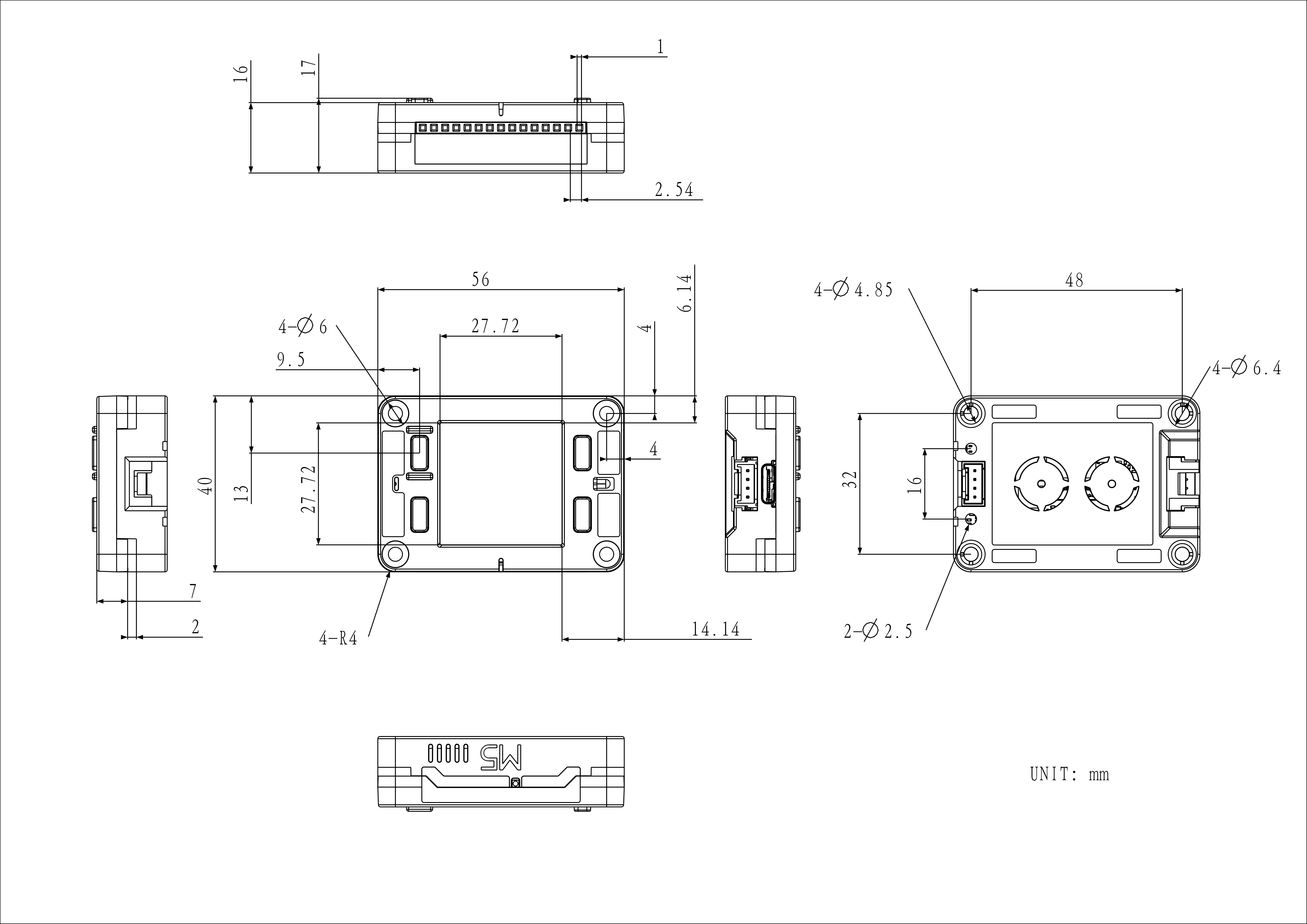
56.0 x 40.0 x 17.0mm
Product Weight
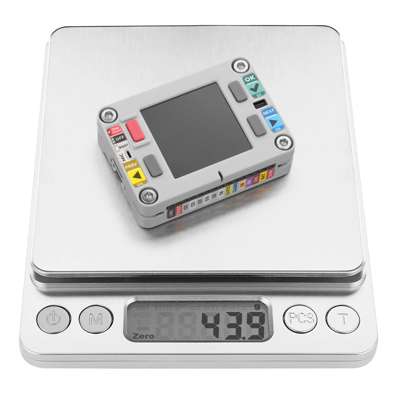
43.9g
Package Size
62.0 x 56.0 x 24.0mm
Gross Weight
60.0g
Learn
Power On/Off
Single-click the power button: power on
Double-click the power button: power off
Enter Download Mode
Connect the device to a computer using a USB Type-C data cable. Press and hold the power button until the green LED on the side starts blinking, indicating that the device has entered download mode.
Connection Instructions
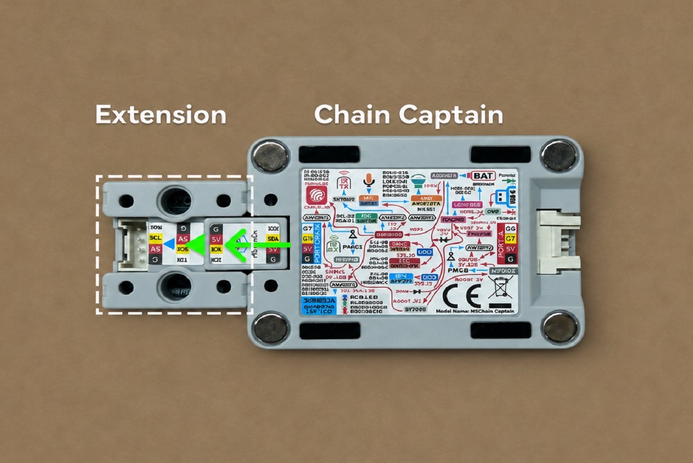
Use the Chain Bridge connector to connect the Chain Captain main controller and various Chain series devices. Pay attention to the direction when connecting; the triangular arrow should point outward from the Chain Captain main controller, as shown below:
On the M5IOE1 I/O expander, PYG1 (IOEG1_TFT_RST) controls the display reset, PYG11 (IOEG11_TFT_BL_EN) controls the backlight, and PYG12 (IOEG12_TFT_L3B_EN) controls the display power supply.
Audio
ESP32-S3R8
G2
G3
ES8311 (0x18)
SCL
SDA
ESP32-S3R8
G38
G39
G40
G41
G42
ES8311
SCLK
ASDOUT
MCLK
LRCK
DSDIN
ESP32-S3R8
G21
AW8737A
SHDN
The M5IOE1 I/O expander's PYG5 (IOEG5_CODER_L3B_EN) controls power to the audio peripherals. The ESP32-S3R8's G21 (G21_SPK_L3B_EN) controls the AW8737A speaker amplifier enable signal.
KEY
ESP32-S3R8
G1
G4
G5
KEY
KEYA (OK)
KEYB (PREV)
KEYC (NEXT)
IMU & RTC
ESP32-S3R8
G2
G3
BMI270 (0x68)
SCL
SDA
RX8130CE (0x32)
SCL
SDA
The always-on 3V3_L0 rail powers the RX8130CE. Its interrupt signal connects to G2 (PMG2_RTC_INT) on the M5PM1.
RGB LED
M5IOE1
PYG8
PYG9
PYG10
RGB LED
G
B
R
On the M5IOE1, PYG8 (IOEG8_G_LED), PYG9 (IOEG9_B_LED), and PYG10 (IOEG10_R_LED) control the green, blue, and red LED channels, respectively, and support PWM dimming.
IR
ESP32-S3R8
G47
G48
IR
IR_RX
IR_TX
The M5IOE1 I/O expander's PYG2 (IOEG2_IR_L3B_EN) controls power to the infrared transmitter and receiver circuits.
HY2.0-4P
HY2.0-4P
Black
Red
Yellow
White
PORT.A
GND
5V
G6 (UART2_TX)
G7 (UART2_RX)
G6 and G7 can be used as general-purpose I/O or configured as UART2 TX and RX, respectively. The M5PM1's G0 (PMG0_GROVE5V_EN) controls the Grove port's 5V output.
HY2.0-4P
Black
Red
Yellow
White
PORT.CHAIN
GND
5V
G18 (UART1_TX)
G17 (UART1_RX)
The M5PM1's G3 (PMG3_CHAIN5V_EN) controls the Chain port's 5V output.
Ext.Port (2.54-15P)
PIN
FUNC
1
GND
2
5VOUT
3
G13
4
G12
5
G11
6
G10
7
G9
8
G8
9
G43
10
G44
11
G0_BOOT
12
CHIP_EN
13
3V3_L2
14
VBAT
15
5VIN
M5PM1
ESP32-S3R8
G2
G3
M5PM1 (0x6E)
SCL
SDA
M5PM1
G0
G1
G2
G3
G4
Grove
PMG0_GROVE5V_EN
ESP32-S3R8
G14 / PMG1_IRQOUT
RTC
PMG2_RTC_INT
Chain
PMG3_CHAIN5V_EN
IMU
PMG4_IMU_INT
G0 (PMG0_GROVE5V_EN) controls the power direction of the Grove port. Driving this pin high enables 5V output. Driving it low disables the output and allows an external 5V input.
G1 (PMG1_IRQOUT) outputs an interrupt signal to GPIO14 on the ESP32-S3R8.
G2 (PMG2_RTC_INT) receives the interrupt from the RX8130CE RTC for scheduled wake-up.
G3 (PMG3_CHAIN5V_EN) controls the power direction of the Chain port. Driving this pin high enables 5V output. Driving it low disables the output and allows an external 5V input.
G4 (PMG4_IMU_INT) receives the BMI270 INT1 interrupt for wake-up on IMU events.
M5PM1
DCDC3V3_EN_PP
LDO3V3_EN_PP
CHG_EN_PP
3V3_L2
PM_3V3_L2_EN
3V3_L1
PM_3V3_L1_EN
CHARGE
PM_CHG_EN
DCDC3V3_EN_PP (PM_3V3_L2_EN) controls the 3V3_L2 supply for the main controller and peripherals.
LDO3V3_EN_PP (PM_3V3_L1_EN) controls the 3V3_L1 supply for the IMU.
CHG_EN_PP (PM_CHG_EN) controls the enable signal for the LGS4056HDA battery charger IC.
M5IOE1
ESP32-S3R8
G2
G3
M5IOE1 (0x4F)
SCL
SDA
M5IOE1
PYG1
PYG2
PYG3
PYG4
PYG5
PYG6
LCD
IOEG1_TFT_RST
IR
IOEG2_IR_L3B_EN
CHARGE
IOEG3_CHG_STA
BOOST
IOEG4_BOOST_L3B_EN
AUDIO
IOEG5_CODER_L3B_EN
Ext.Port (2.54-15P)
IOEG6_HEADER5V_EN
M5IOE1
PYG8
PYG9
PYG10
PYG11
PYG12
LCD
IOEG11_TFT_BL_EN
IOEG12_TFT_L3B_EN
RGB LED
IOEG8_G_LED
IOEG9_B_LED
IOEG10_R_LED
PYG1 (IOEG1_TFT_RST) controls the display reset.
PYG2 (IOEG2_IR_L3B_EN) controls the IR_3V3_L3B supply for the infrared transmitter and receiver circuits.
PYG3 (IOEG3_CHG_STA) reads the charging status.
PYG4 (IOEG4_BOOST_L3B_EN) controls the SY7088DGC boost circuit, which generates BOOST_5V for the 5V outputs on Grove, Chain, and Ext.Port.
PYG5 (IOEG5_CODER_L3B_EN) controls the CODER_3V3_L3B supply for the ES8311 codec and the MEMS microphone. The ESP32-S3R8's G21 (G21_SPK_L3B_EN) independently controls the AW8737A speaker amplifier enable signal.
PYG6 (IOEG6_HEADER5V_EN) controls the 5V output switch for Ext.Port (2.54-15P).
PYG8 (IOEG8_G_LED) controls the green LED via PWM.
PYG9 (IOEG9_B_LED) controls the blue LED via PWM.
PYG10 (IOEG10_R_LED) controls the red LED via PWM.
PYG11 (IOEG11_TFT_BL_EN) controls the display backlight through Q7 and supports PWM dimming.
PYG12 (IOEG12_TFT_L3B_EN) controls the TFT_3V3_L3B supply for the display.