


Arduino Quick Start
2. Devices & Examples
3. M5Unified
4. M5GFX
5. Extensions
Unit
Atomic
Tab5
IoT
Accessories
Chain Series Device Bus Communication Tutorial
1. Chain Bus Overview
The M5Stack Chain Bus is a daisy-chain topology based on a UART communication interface, consisting of one Master and multiple Nodes. The master acts as the starting point of the chain, while the remaining nodes are connected sequentially on the same bus. During operation, each node communicates with the master by forwarding data packets hop by hop along the chain.
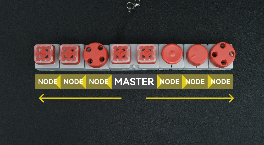
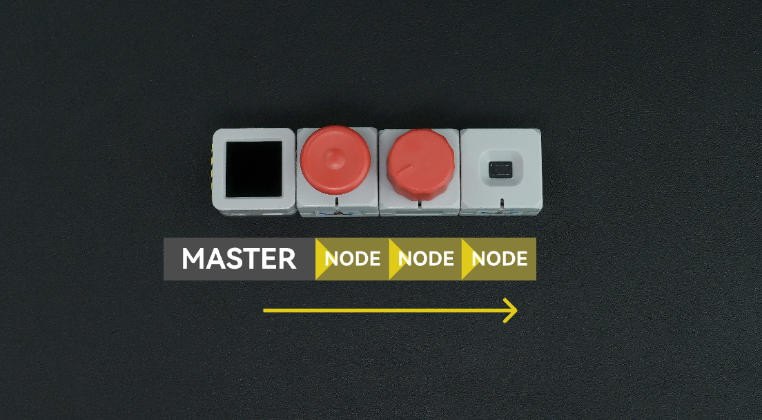
Master
The master device communicates with the Chain Bus via a UART interface. A single master can expand multiple Chain Bus lines, depending on the number of available UART interfaces, enabling flexible multi-bus and multi-node expansion.
Node
Chain nodes typically integrate an STM32G031G8U6 as the core controller and use the Chain series dedicated UART daisy-chain communication protocol for data exchange. Each node features two onboard HY2.0-4P expansion connectors, which are used for data input (IN) and data output (OUT) respectively. When connecting devices, pay attention to the connection direction: the master should be connected to the node’s data input (IN), and then the node’s data output (OUT) should be connected to the input of the next node in the chain.
- Chain Series Masters:
- Chain Series Connectors:
- Chain Series Input Devices:
It is recommended to use Chain DualKey or an Atom series controller combined with the Atomic ToChain Base as the Chain Bus master.
2.Example Program
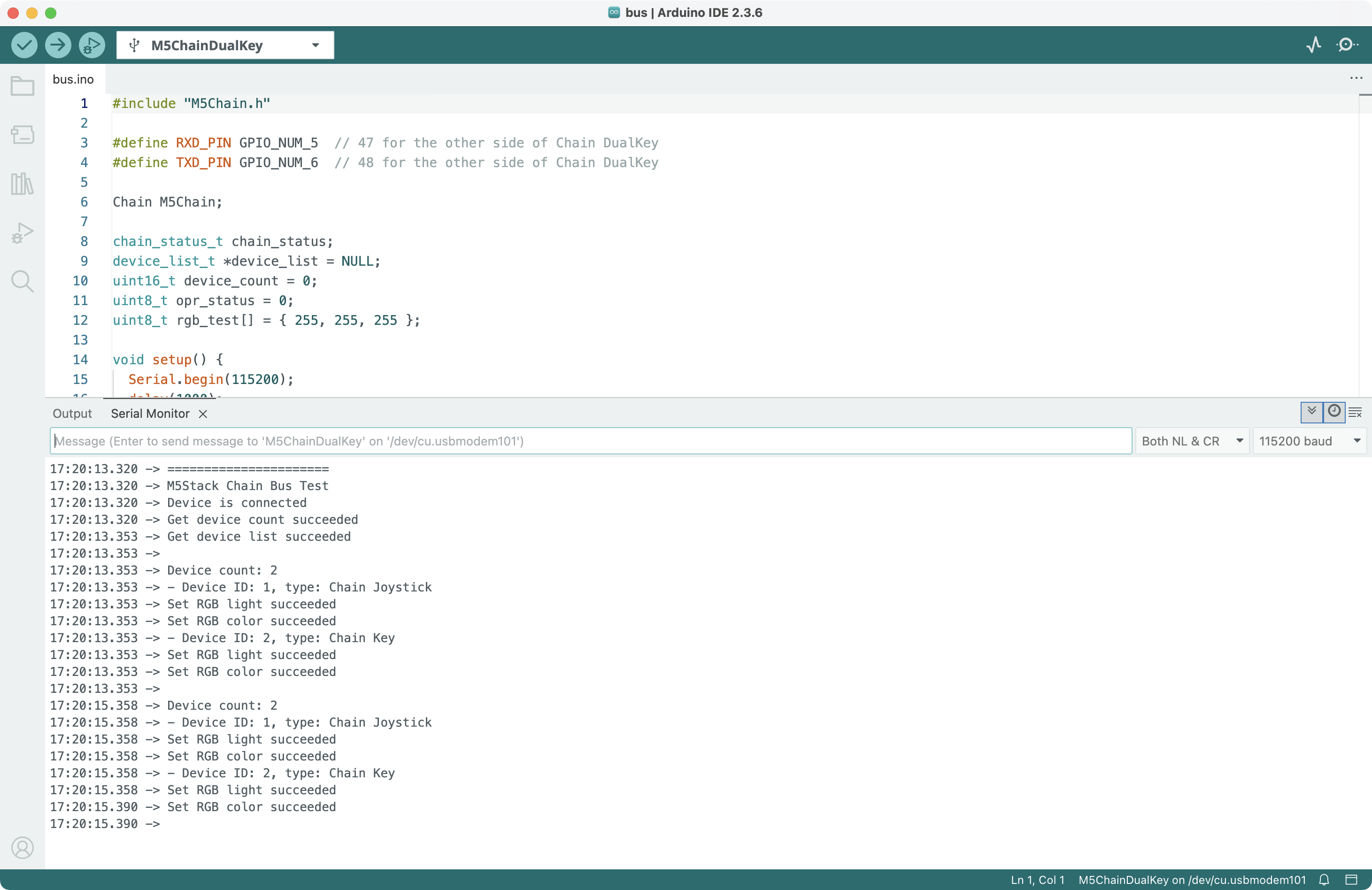
M5Chain library version >= 1.0.0
#include "M5Chain.h"

#define RXD_PIN GPIO_NUM_5  // 47 for the other side of Chain DualKey
#define TXD_PIN GPIO_NUM_6  // 48 for the other side of Chain DualKey

Chain M5Chain;

chain_status_t chain_status;
device_list_t *device_list = NULL;
uint16_t device_count = 0;
uint8_t opr_status = 0;
uint8_t rgb_test[] = { 255, 255, 255 };

void setup() {
  Serial.begin(115200);
  delay(1000);
  Serial.println("======================");
  Serial.println("M5Stack Chain Bus Test");
  M5Chain.begin(&Serial2, 115200, RXD_PIN, TXD_PIN);
}

void loop() {
  Serial.println();
  delay(2000);

  if (!M5Chain.isDeviceConnected()) {
    Serial.println("No device connected");
    return;
  }

  chain_status = M5Chain.getDeviceNum(&device_count);
  if (chain_status == CHAIN_OK) {
    device_list = (device_list_t *)malloc(sizeof(device_list_t));
    device_list->count = device_count;
    device_list->devices = (device_info_t *)malloc(sizeof(device_info_t) * device_count);
  } else {
    Serial.printf("Get device count failed, chain status: %d\r\n", chain_status);
    return;
  }

  if (!M5Chain.getDeviceList(device_list)) {
    Serial.println("Get device list failed");
    return;
  }

  if (device_list == NULL) {
    Serial.println("Device list is NULL");
    return;
  }

  Serial.printf("Device count: %d\r\n", device_list->count);

  for (int i = 0; i < device_list->count; i++) {
    Serial.print("- Device ID: ");
    Serial.print(device_list->devices[i].id);
    Serial.print(", type: ");
    switch (device_list->devices[i].device_type) {
      case CHAIN_UNKNOWN_TYPE_CODE:
        Serial.println("Unknown");
        break;
      case CHAIN_ENCODER_TYPE_CODE:
        Serial.println("Chain Encoder");
        break;
      case CHAIN_ANGLE_TYPE_CODE:
        Serial.println("Chain Angle");
        break;
      case CHAIN_KEY_TYPE_CODE:
        Serial.println("Chain Key");
        break;
      case CHAIN_JOYSTICK_TYPE_CODE:
        Serial.println("Chain Joystick");
        break;
      case CHAIN_TOF_TYPE_CODE:
        Serial.println("Chain ToF");
        break;
        // case CHAIN_UART_TYPE_CODE:
        //   Serial.println("Chain UART");
        //   break;
        // case CHAIN_SWITCH_TYPE_CODE:
        //   Serial.println("Chain Switch");
        //   break;
        // case CHAIN_PEDAL_TYPE_CODE:
        //   Serial.println("Chain Pedal");
        //   break;
        // case CHAIN_PIR_TYPE_CODE:
        //   Serial.println("Chain PIR");
        //   break;
        // case CHAIN_MIC_TYPE_CODE:
        //   Serial.println("Chain Mic");
        //   break;
        // case CHAIN_BUZZER_TYPE_CODE:
        //   Serial.println("Chain Buzzer");
        //   break;
    }

    // Device ID, LED brightness (0-100), operation status pointer
    chain_status = M5Chain.setRGBLight(device_list->devices[i].id, 100, &opr_status);
    if (chain_status == CHAIN_OK && opr_status) {
      Serial.println("  Set RGB brightness succeeded");
    } else {
      Serial.printf("  Set RGB brightness failed, chain status: %d, operation status: %d\r\n", chain_status, opr_status);
    }

    rgb_test[0] = random(0, 256);  // [0, 255]
    rgb_test[1] = random(0, 256);  // [0, 255]
    rgb_test[2] = random(0, 256);  // [0, 255]

    // Device ID, LED start index, LED count, RGB color, size of RGB color, operation status pointer
    chain_status = M5Chain.setRGBValue(device_list->devices[i].id, 0, 1, rgb_test, 3, &opr_status);
    if (chain_status == CHAIN_OK && opr_status) {
      Serial.println("  Set RGB color succeeded");
    } else {
      Serial.printf("  Set RGB color failed, chain status: %d, operation status: %d\r\n", chain_status, opr_status);
    }
  }
}Use the Chain Bridge connector to connect the main controller Chain DualKey and various Chain series input devices. Pay attention to the direction when connecting — the triangle arrow should point outward from the main controller Chain DualKey, as shown below:
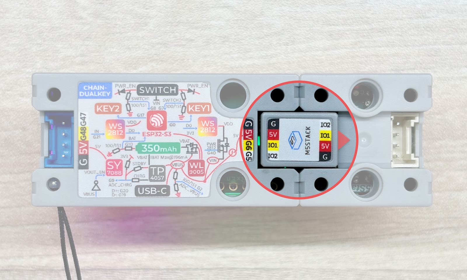
Compile and upload the program to the device. The program will detect every 2 seconds the devices connected to the Chain Bus on the G5 and G6 pins of the Chain DualKey, print the results to the serial monitor, and randomly change the color of the RGB LED. You can hot-plug multiple Chain series devices during program execution.
To use both interfaces on Chain DualKey simultaneously, you need to create two instances of the Chain class in your program. Each instance manages the devices connected to its respective interface.
3.API
Operation Result Status Codes
typedef enum {
    CHAIN_OK                  = 0x00,  // Operation successful
    CHAIN_PARAMETER_ERROR     = 0x01,  // Parameter error
    CHAIN_RETURN_PACKET_ERROR = 0x02,  // Return packet error
    CHAIN_BUSY                = 0x04,  // Device is busy
    CHAIN_TIMEOUT             = 0x05   // Operation timeout
} chain_status_t;begin
Function Prototype:
void begin(HardwareSerial *serial, unsigned long baud = 115200, int8_t rxPin = -1, int8_t txPin = -1);Function Description:
- Initialize the Chain Bus communication bus
Input Parameters:
HardwareSerial *serial- Pointer to the hardware serial object used for serial communication
unsigned long baud- Baud rate for serial communication, default is 115200
int8_t rxPin- GPIO number of the signal receive pin
int8_t txPin- GPIO number of the signal transmit pin
Return Value:
- null
isDeviceConnected
Function Prototype:
bool isDeviceConnected();Function Description:
- Check whether any device is connected to the Chain Bus
Input Parameters:
- null
Return Value:
booltrue: Device(s) connectedfalse: No device connected
getDeviceNum
Function Prototype:
chain_status_t getDeviceNum(uint16_t *deviceNum);Function Description:
- Retrieve the number of devices connected to the Chain Bus
Input Parameters:
uint16_t *deviceNum- Pointer used to store the number of connected devices
Return Value:
chain_status_t- Operation result status code
getDeviceList
Function Prototype:
bool getDeviceList(device_list_t *list);Function Description:
- Retrieve the list of devices connected to the Chain Bus
Input Parameters:
device_list_t *list- Pointer used to store the device list. The structure contains the number of devices and an array of detailed information for each device.
typedef struct {
    uint16_t count;          // Number of devices
    device_info_t *devices;  // Array of devices
} device_list_t;Return Value:
booltrue: Successfully retrievedfalse: Failed to retrieve
Device Details
The device list obtained through the getDeviceList function is of type device_list_t. This structure contains the number of devices and an array of detailed information for each device. Each device’s detailed information is represented by the type device_info_t, whose structure includes the device ID and device type.
typedef struct {
    uint16_t id;                      // Device ID
    chain_device_type_t device_type;  // Device type
} device_info_t;- Device ID
Each device connected to a single Chain Bus has a unique Device ID used for individual identification and control. The ID value of each device is automatically assigned by the system and increases starting from 1, following the connection order from the controller outward:
Main Controller -> 1 -> 2 -> 3 -> ...- Device Type
The device type enumeration values are as follows:
typedef enum {
    CHAIN_UNKNOWN_TYPE_CODE  = 0x0000,  // Unknown device type
    CHAIN_ENCODER_TYPE_CODE  = 0x0001,  // Chain Encoder
    CHAIN_ANGLE_TYPE_CODE    = 0x0002,  // Chain Angle
    CHAIN_KEY_TYPE_CODE      = 0x0003,  // Chain Key
    CHAIN_JOYSTICK_TYPE_CODE = 0x0004,  // Chain Joystick
    CHAIN_TOF_TYPE_CODE      = 0x0005,  // Chain ToF
    CHAIN_UART_TYPE_CODE     = 0x0006,  // Chain UART
    CHAIN_SWITCH_TYPE_CODE   = 0x0007,  // Chain Switch
    CHAIN_PEDAL_TYPE_CODE    = 0x0008,  // Chain Pedal
    CHAIN_PIR_TYPE_CODE      = 0x0009,  // Chain PIR
    CHAIN_MIC_TYPE_CODE      = 0x000A,  // Chain Microphone
    CHAIN_BUZZER_TYPE_CODE   = 0x000B,  // Chain Buzzer
} chain_device_type_t;setRGBLight
Function Prototype:
chain_status_t setRGBLight(uint16_t id, uint8_t rgbBrightness, uint8_t *operationStatus);Function Description:
- Set the brightness of the RGB LED on the device
Input Parameters:
uint16_t id- Device ID
uint8_t rgbBrightness- Brightness value (0–100)
uint8_t *operationStatus- Pointer used to store the operation result (0 = operation failed, 1 = operation succeeded)
Return Value:
chain_status_t- Operation result status code
setRGBValue
Function Prototype:
chain_status_t setRGBValue(uint16_t id, uint8_t index, uint8_t num, uint8_t *rgb, uint8_t size, uint8_t *operationStatus);Function Description:
- Set the color of the RGB LEDs on the device
Input Parameters:
uint16_t id- Device ID
uint8_t index- LED index to control, starting from 0
uint8_t num- Number of LEDs to control
uint8_t *rgb- Pointer to the RGB color array, formatted as
[R0, G0, B0, R1, G1, B1, ...]
- Pointer to the RGB color array, formatted as
uint8_t size- Length of the RGB color array, must be equal to
num * 3
- Length of the RGB color array, must be equal to
uint8_t *operationStatus- Pointer used to store the operation result (0 = operation failed, 1 = operation succeeded)
Return Value:
chain_status_t- Operation result status code
4.Comm. Mechanism
The Chain series devices support hot-swapping of multiple and diverse modules, as well as daisy-chain communication. This is enabled by the underlying Chain Bus communication mechanism, which includes device discovery, ID assignment, command transmission, and more.
Device ID
Each device connected on a Chain Bus has a unique device ID used for individual identification and control. The ID for each device is automatically assigned by the system, starting from 1 and increasing sequentially in the order of connection outward from the main controller.
Device Type
The device type chain_device_type_t is used to distinguish between different device categories, such as CHAIN_ENCODER_TYPE_CODE, CHAIN_KEY_TYPE_CODE, and others.
Data Trans. & Response
Packets sent from the main controller to Chain Bus originate from the controller's serial interface and enter the device chain. The first device in the chain checks the target device ID contained in each packet. If ID == 1, the device identifies itself as the target and processes the packet directly. If ID > 1, the device performs ID = ID - 1 and forwards the packet to the next device in the chain. This process continues until the packet reaches the intended target device, where ID == 1, and the device handles the data accordingly.
After processing the packet, the device sends a response packet back in the reverse direction. Before forwarding the response, each device executes ID = ID + 1, and eventually the response packet returns to the main controller, allowing the controller to identify which device generated the response.
Tail Device
During power-up initialization, each device in the Chain series treats itself as the "tail device" of the chain by default. Once a device receives the first complete data packet from the next device in the chain, it updates its internal state to indicate that it is no longer the tail device.
Heartbeat Packet
A heartbeat packet is a special type of packet used for periodic communication within the Chain Bus. Each device in the chain actively sends a heartbeat packet to the next device once per second. Upon receiving the heartbeat packet, the next device immediately returns it unchanged as a response.
If a device sends three consecutive heartbeat packets without receiving any response, it determines that the next device is offline and updates its state to "tail device".
The main controller (host) also sends heartbeat packets onto the chain. If it receives a valid response, it indicates that devices are connected on the chain; if no response is received, it indicates that no devices are connected.
Enumeration Packet
An enumeration packet is another special type of Chain Bus packet used to update the chain's connection topology. When a new device is connected to the chain, it automatically sends 3 enumeration requests (each spaced 180 ms apart) to notify the main controller that the chain structure has changed. After receiving such a request, the main controller initiates a device enumeration process to refresh the connection structure and update the device list.
Conversely, when part of the chain becomes disconnected, the device preceding the break will fail to receive heartbeat responses. It will then change its state from "non-tail device" to "tail device" and actively send 3 enumeration requests to notify the main controller of the change.
For enumeration commands initiated by the main controller, the tail device is responsible for terminating the enumeration sequence, sending the result packet back to the controller, and completing the enumeration for the entire chain.