Stamp-S3A PIN1.27
SKU:S007-PIN127-V033



Description
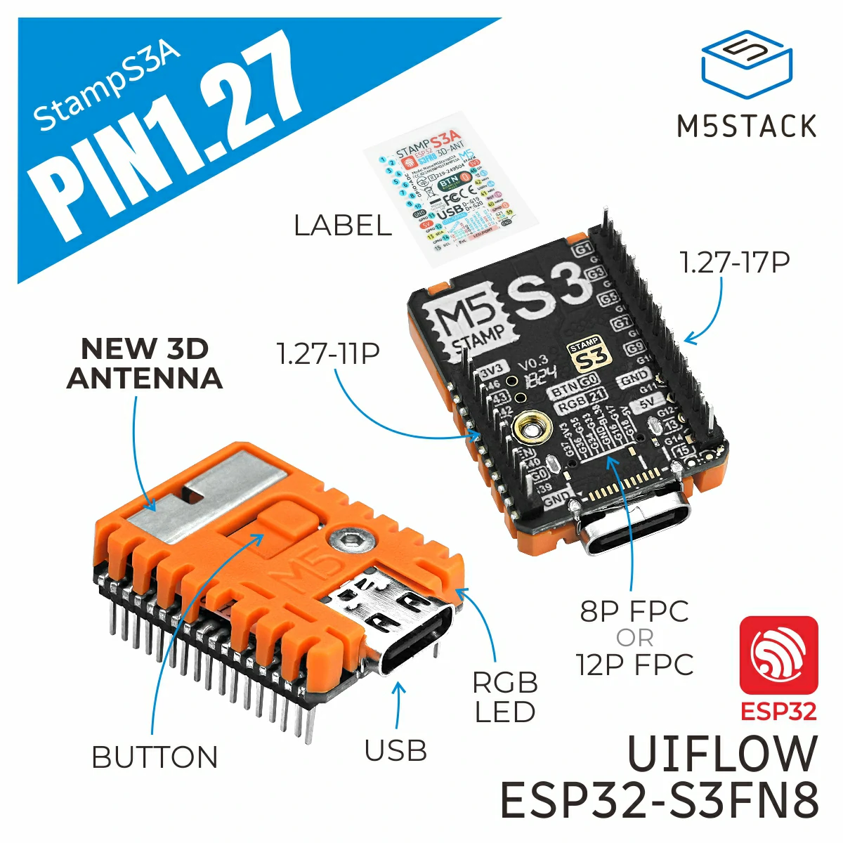
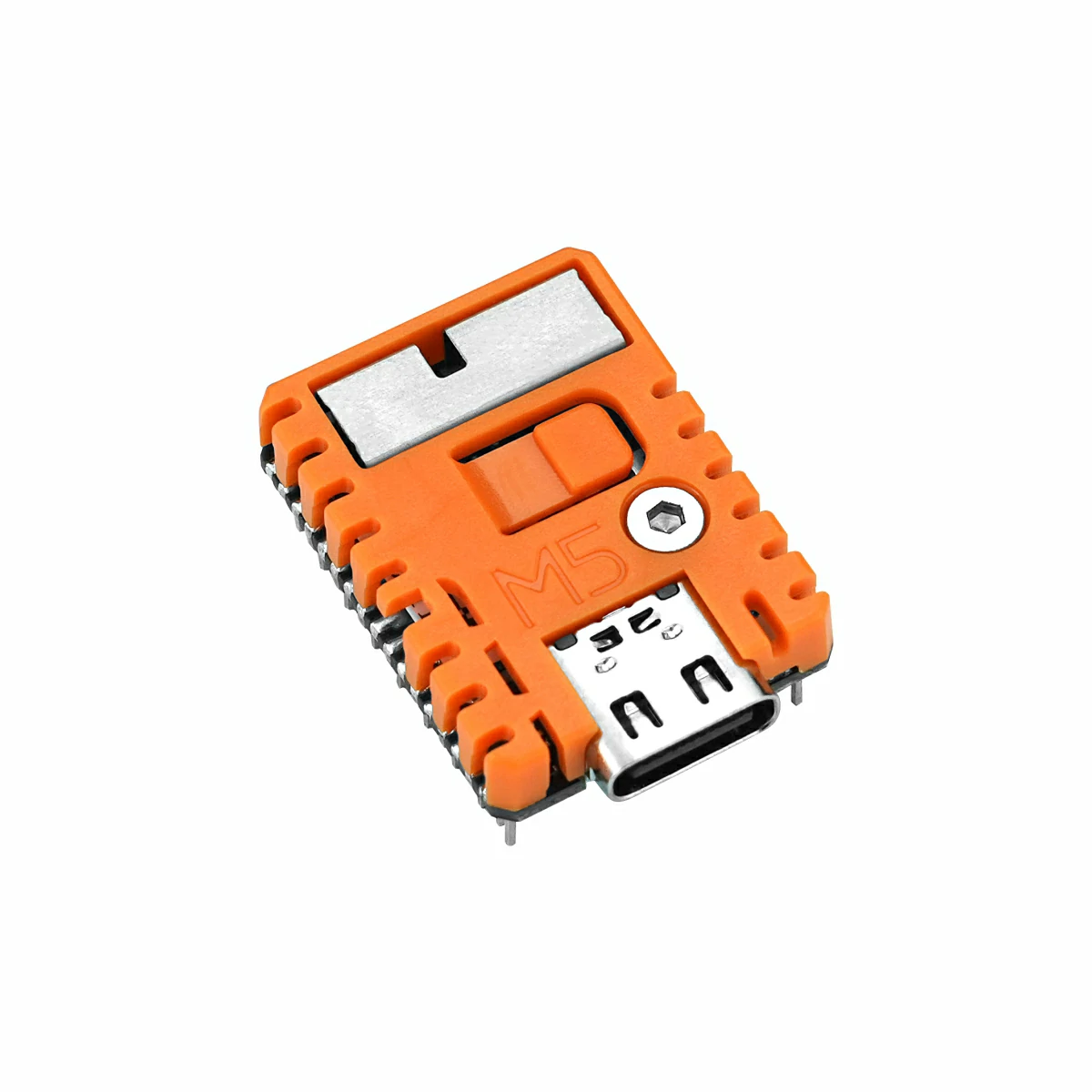
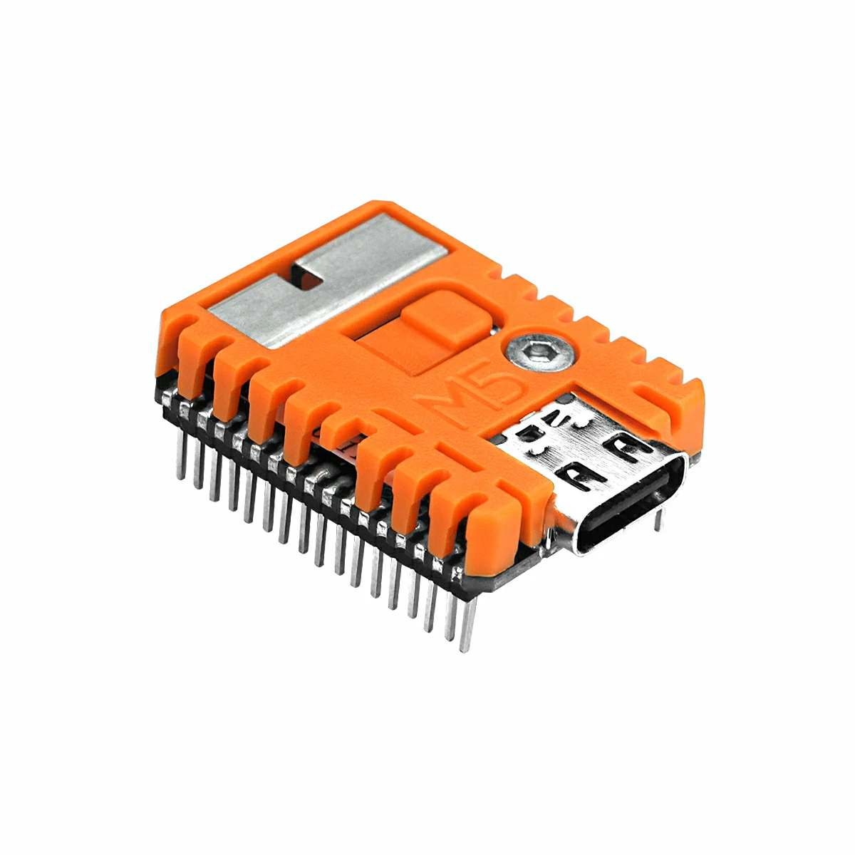
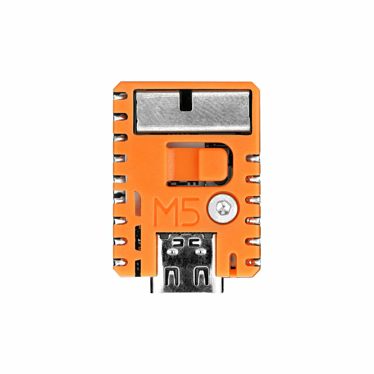
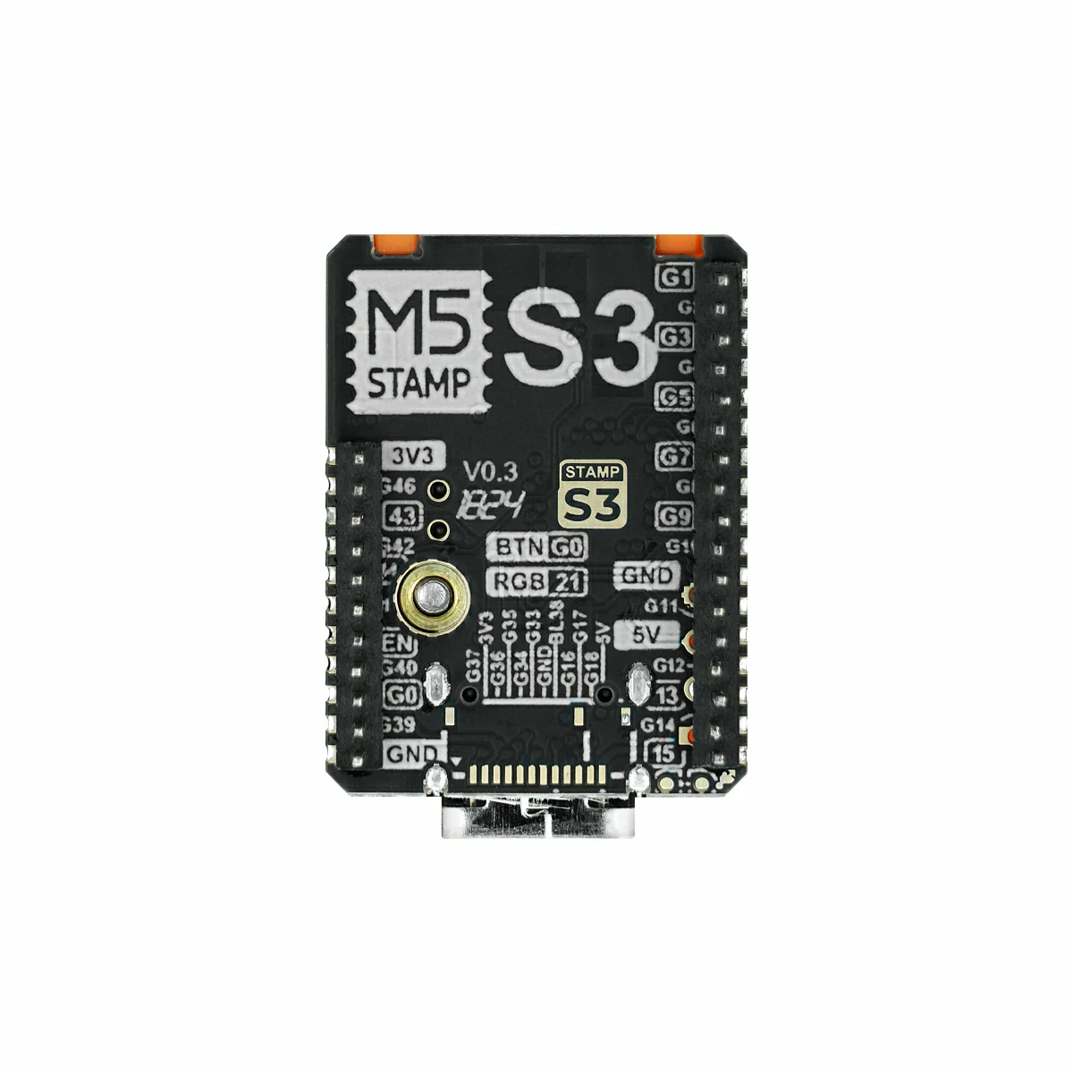
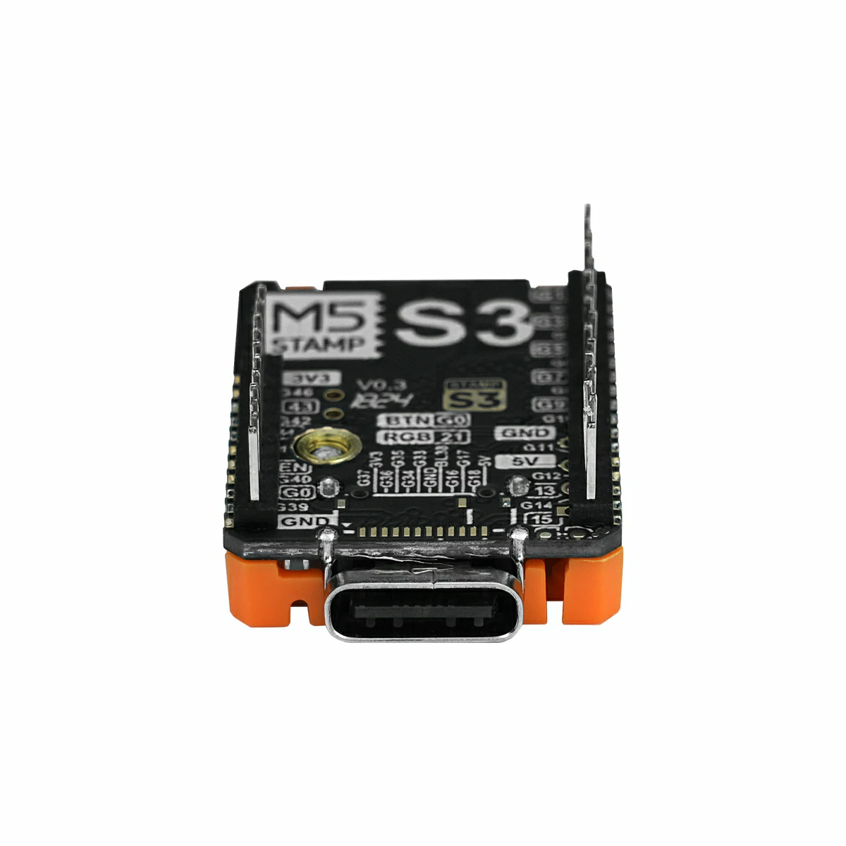
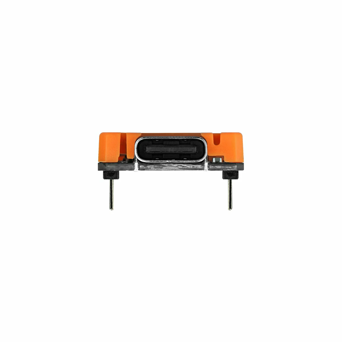
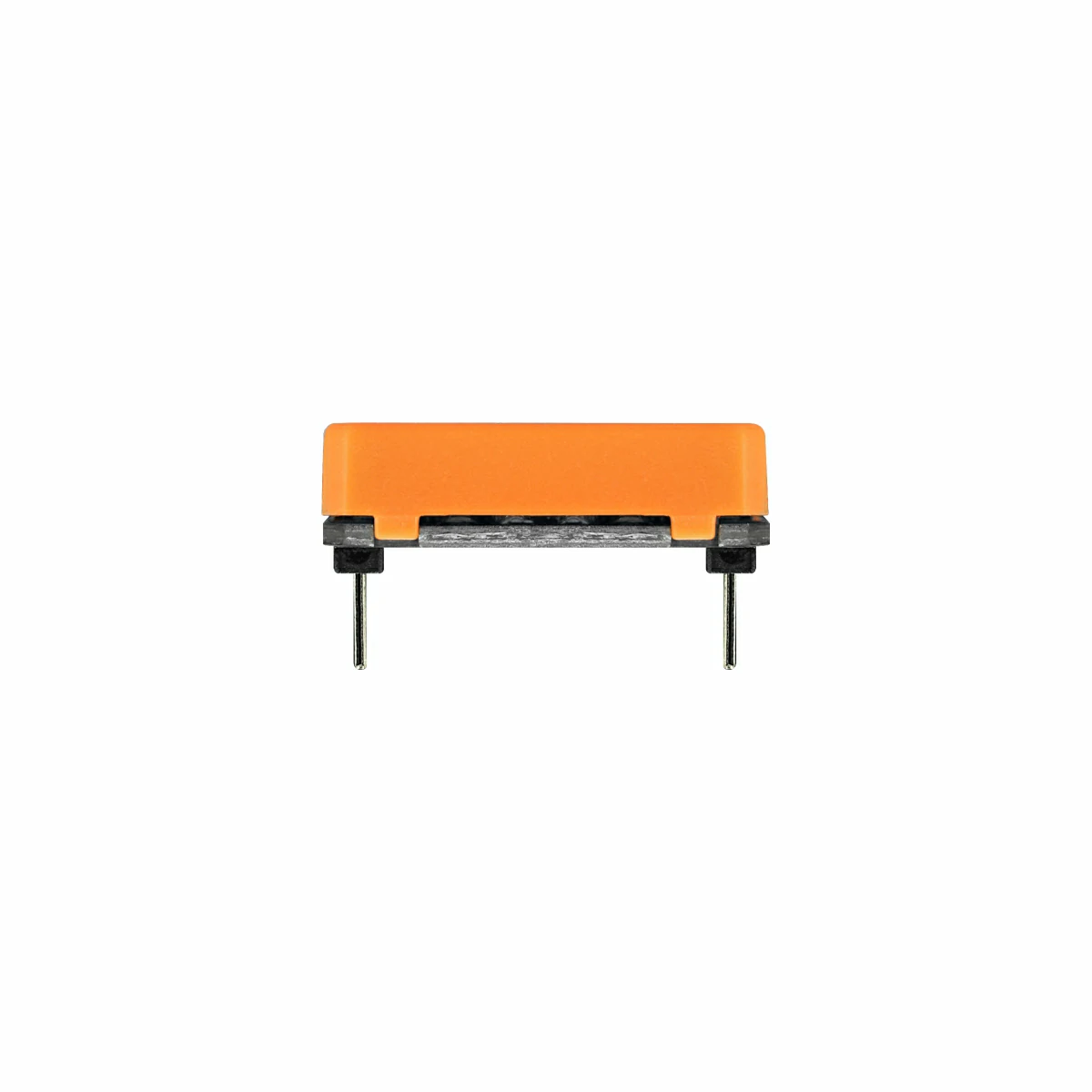
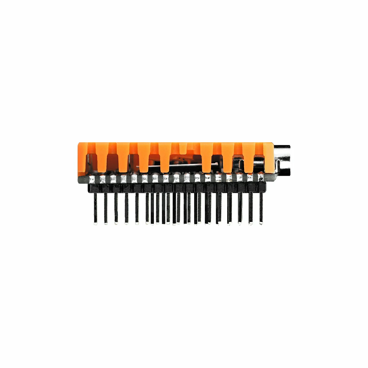
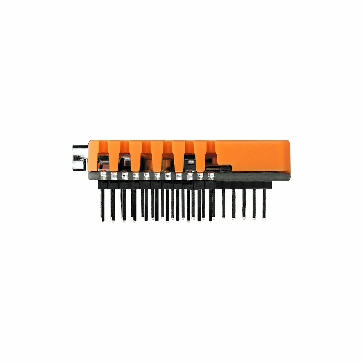
Stamp-S3A PIN1.27 is a highly-integrated embedded module based on the Espressif ESP32-S3FN8. It features a 240 MHz Xtensa® 32-bit LX7 dual-core processor, integrates 8 MB Flash, a programmable RGB LED, and a user button. The deeply optimized 3D antenna design delivers stronger wireless performance. Twenty-three GPIOs are broken out and a 1.27 mm-pitch SMT pin header is pre-soldered, providing an even smaller footprint for high-density PCB integration and enabling developers to build compact applications quickly.
Tutorial
Features
- ESP32-S3FN8 (2.4 GHz Wi-Fi)
- 1.27 mm-pitch SMT interface
- 23 multifunctional GPIOs
- 8 MB Flash
- Rich I/O breakout supporting multiple application forms (SMT, DIP, fly-wire)
- Integrated programmable RGB LED and button
- Development Platform
- UiFlow2
- Arduino IDE
- ESP-IDF
- PlatformIO
Includes
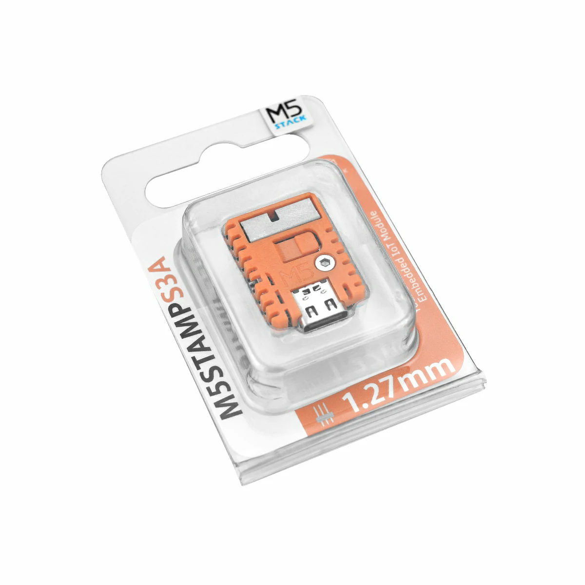
- 1 x Stamp-S3A PIN1.27
- 1 x Pin Sticker
Applications
- Smart home
- Intelligent IoT devices
- Industrial control terminals
- Wearable devices
Specifications
| Specification | Parameter |
|---|---|
| SoC | ESP32-S3FN8@Xtensa LX7 dual-core, main frequency up to 240MHz |
| Flash | 8MB |
| DC-DC | MUN3CAD01-SC |
| Wi-Fi | 2.4 GHz Wi-Fi |
| Input Voltage | DC 5V |
| HMI | Programmable physical button × 1, programmable RGB LED (WS2812B-2020) × 1 |
| Antenna Type | 2.4 GHz 3D antenna |
| Module Resource I/F | Touch Sensor, SD/SDIO/MMC Host Ctrl, SPI, SDIO/SPI Slave Ctrl, EMAC, Motor PWM, LED PWM, UART, I2C, I2S, GPIO, Pulse Counter |
| IO Interfaces × 23 | G0/G1/G2/G3/G4/G5/G6/G7/G8/G9/G10/G11/G12/G13/G14/G15/G39/G40/G41/G42/G43/G44/G46 |
| IO Pitch | 1.27 mm |
| LCD FPC Pitch | 0.5 mm @ 12 P or 8 P |
| Operating Temp. | 0 ~ 40 °C |
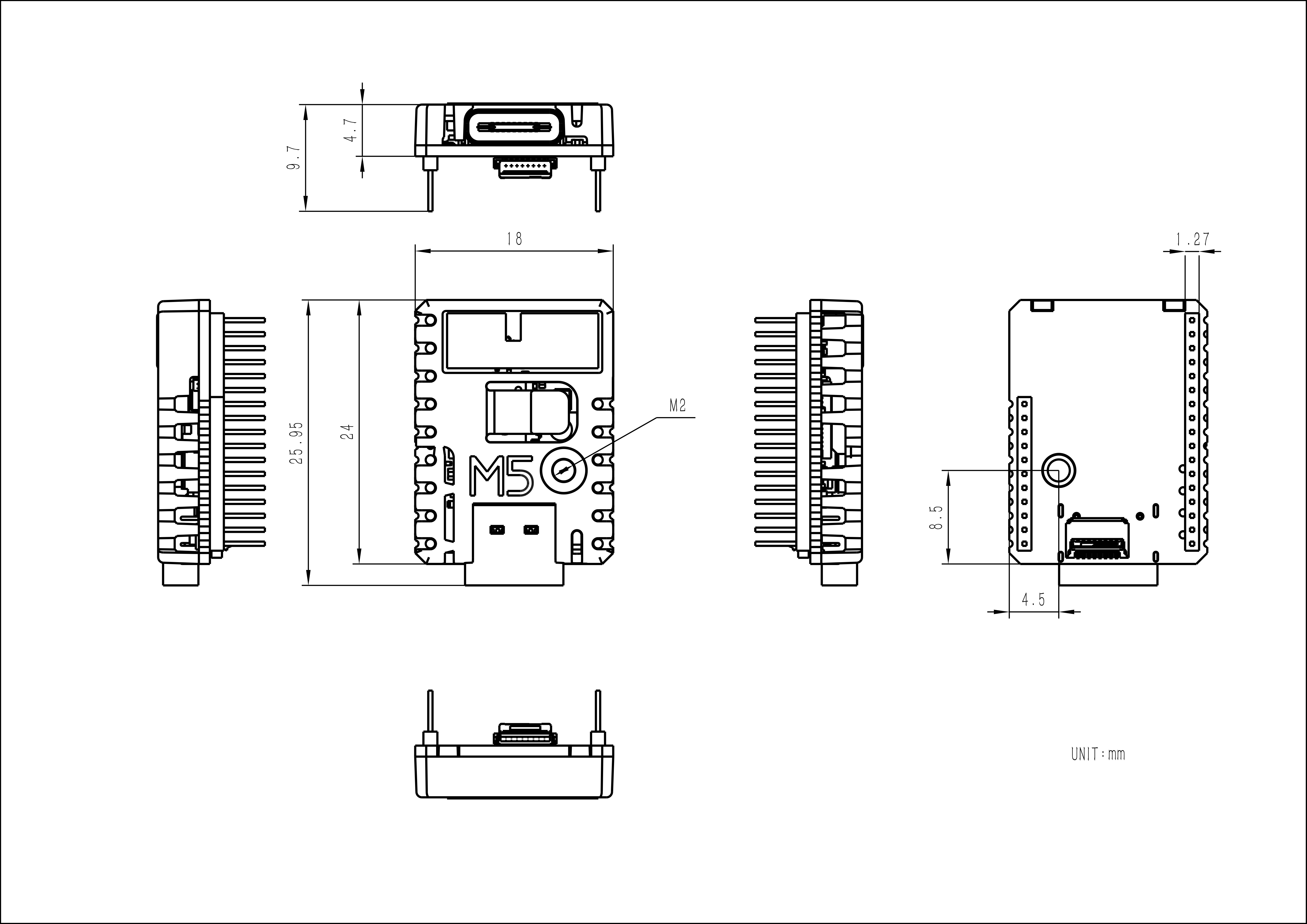
| Product Size | 26.0 × 18.0 × 4.7 mm |
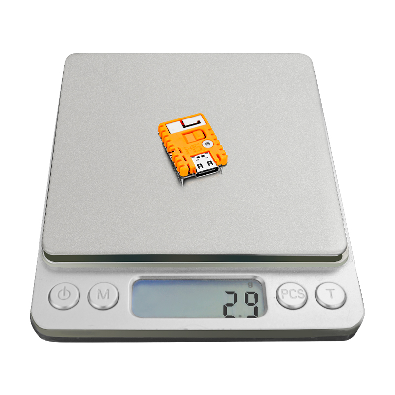
| Product Weight | 3.1 g |
| Package Size | 74.0 × 48.0 × 13.0 mm |
| Gross Weight | 7.6 g |
Learn
Download Mode
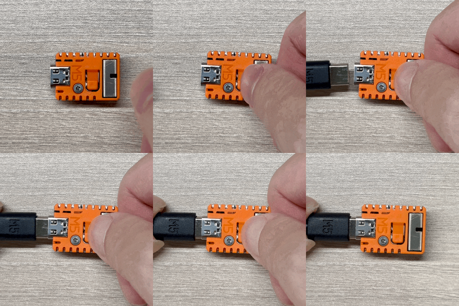
To enter download mode, hold the G0 button on the Stamp-S3A PIN1.27 before powering on, then release it after power is applied.
Additional Notes
- ESP32-S3 pins G0 and G46 are strapping pins that determine the boot mode. By default, G0 is pulled-up and G46 is internally pulled-down, enabling the chip to boot from SPI Flash normally. Do not pull G46 high before the chip boots; otherwise, the chip will fail to start. Refer to the Strapping-Pin section of the ESP32-S3 datasheet for details.
- An SPI interface for a TFT display is reserved on the back of the module. Compatible FPC connector specifications are 8 PIN and 12 PIN.
Schematics
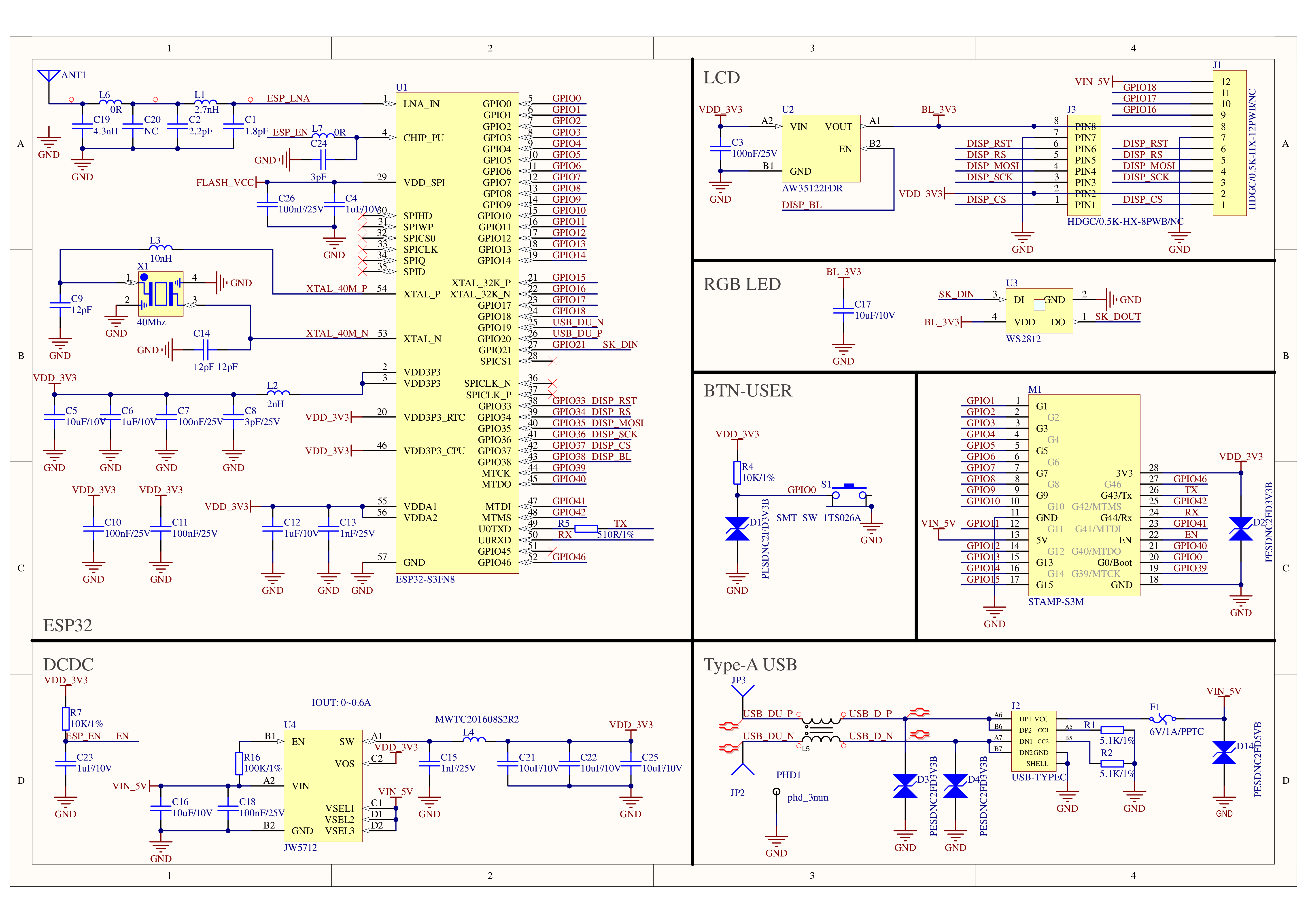

PinMap

Model Size
Stamp-S3A PIN1.27 Model Size PDF
PCB
Structure
Datasheets
Softwares
Arduino
UiFlow2
Video
- Stamp-S3A PIN1.27 Product Introduction
Product Comparison
| Product Comparison Item | Stamp-S3A PIN1.27  | Stamp-S3 PIN1.27  |
|---|---|---|
| RGB LED Control Logic | RGB LED power is multiplexed with the reserved screen FPC bus backlight | Powered as soon as power is applied |
| Antenna Design | Optimized antenna design with better signal reception | Conventional antenna design |
| Module Boot Button | Improved tactile feel; 4.0 × 3.0 × 2.0 mm button | 2.6 × 1.6 × 0.55 mm button |
| Power Consumption | Optimized for lower power consumption | Standard design |
To compare information on the Stamp series products, you can visit the Product Selection Table, check the target products, and get the comparison results. The selection table covers key information such as core parameters and functional features, and supports comparison of multiple products simultaneously.

