Arduino Quick Start
2. Devices & Examples
3. M5Unified
4. M5GFX
5. Extensions
Unit
Atomic
Tab5
IoT
Accessories
Stamp-S3A Arduino Program Compilation & Upload
1.Preparation
- 1.Arduino IDE Installation: Refer to the Arduino IDE Installation Guide to complete the IDE installation.
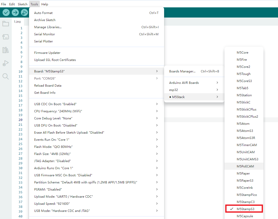
- 2.Board Manager Installation: Refer to the Basic Environment Setup Guide to complete the M5Stack board manager installation and select the development board
M5StampS3.
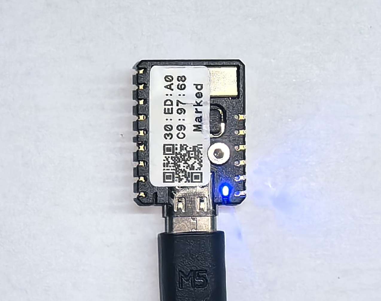
2.Download Mode
Press and hold the G0 button on the Stamp-S3A, and connect the device to the computer via a USB cable. At this time, the port can be recognized on the computer, indicating that the device has entered the download mode.
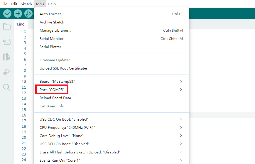
3.Port Selection
Wait for the device to successfully recognize the port, and select the corresponding device's port in Arduino IDE.
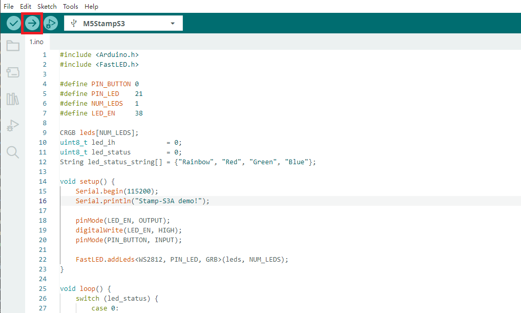
4.Program Compilation & Upload
Enter the following code in the Arduino IDE workspace, and click the upload button. The program will be automatically compiled and uploaded.
2.To control the standby power consumption, the Stamp-S3A RGB LED needs to enable the LED chips, which means it requires a high-level control of the
LED_EN in the following code.#include <Arduino.h>
#include <FastLED.h>
#define PIN_BUTTON 0
#define PIN_LED 21
#define NUM_LEDS 1
#define LED_EN 38
CRGB leds[NUM_LEDS];
uint8_t led_ih = 0;
uint8_t led_status = 0;
String led_status_string[] = {"Rainbow", "Red", "Green", "Blue"};
void setup() {
Serial.begin(115200);
Serial.println("Stamp-S3A demo!");
pinMode(LED_EN, OUTPUT);
digitalWrite(LED_EN, HIGH);
pinMode(PIN_BUTTON, INPUT);
FastLED.addLeds<WS2812, PIN_LED, GRB>(leds, NUM_LEDS);
}
void loop() {
switch (led_status) {
case 0:
leds[0] = CHSV(led_ih, 255, 255);
break;
case 1:
leds[0] = CRGB::Red;
break;
case 2:
leds[0] = CRGB::Green;
break;
case 3:
leds[0] = CRGB::Blue;
break;
default:
break;
}
FastLED.show();
led_ih++;
delay(15);
if (!digitalRead(PIN_BUTTON)) {
delay(5);
if (!digitalRead(PIN_BUTTON)) {
led_status++;
if (led_status > 3) led_status = 0;
while (!digitalRead(PIN_BUTTON))
;
Serial.print("LED status updated: ");
Serial.println(led_status_string[led_status]);
}
}
}
After uploading the code, the RGB LED on the Stamp-S3A device will light up automatically. Pressing the button allows you to cycle through the display colors of the LED. At the same time, the device will output the current light status information (such as color values or modes) through the serial port, facilitating debugging and interactive feedback.