
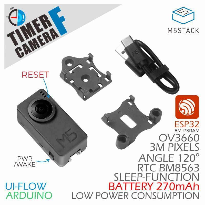
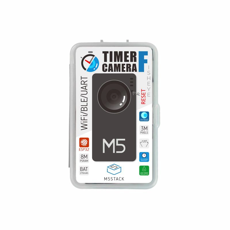
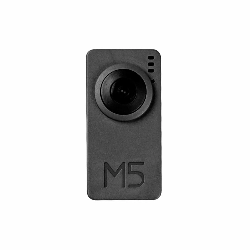
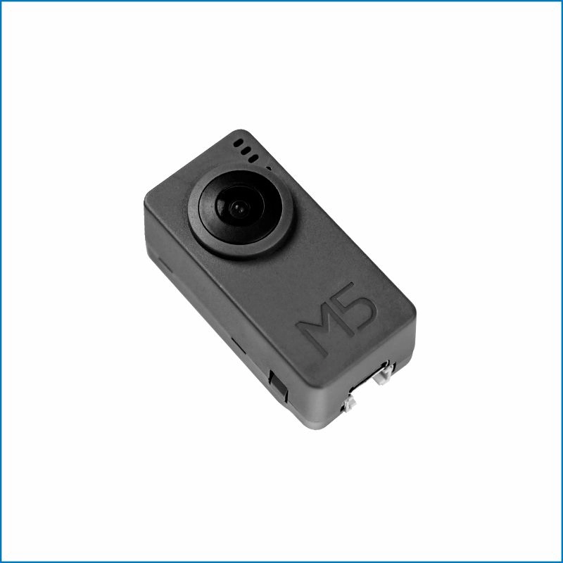
TimerCamera-F
SKU:U082-F

Description
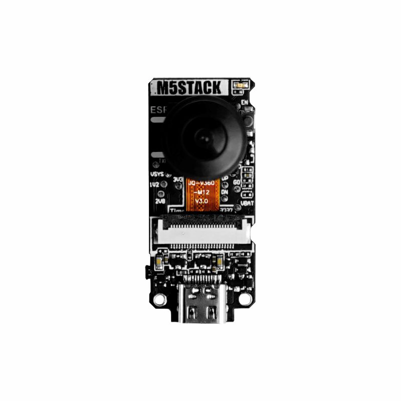
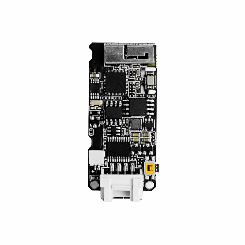
TimerCamera-F is a fisheye camera module based on ESP32-D0WDQ6-V3, with onboard 8M PSRAM and 4M Flash. It features a 3MP camera (OV3660) with a DFOV of 120°, capable of capturing photos at a maximum resolution of 2048x1536. The camera is designed with ultra-low power consumption in mind, with an integrated RTC (BM8563) that exposes the IRQ signal for device sleep and timed wake-up (sleep current can be as low as 2μA). With timed photo capture (one photo per hour), the built-in 270mAh battery can provide over a month of battery life. The module supports WiFi image transmission and USB port debugging, with a HY2.0-4P port output at the bottom for expanding other peripherals. The onboard LED status indicator and reset button facilitate program development and debugging. In terms of applications, M5Stack provides some simple and efficient application development methods and interfaces for the TimerCAM series, offering convenience for user usage and development. (Including PC/Mobile photo capture apps, cloud-based HTTP interfaces for timed photo capture, etc.)
Features
- ESP32-based design
- WiFi image transmission
- Timed sleep and wake-up
- Status indicator
- Ultra-low power design
- Built-in 270mAh battery
- Programming platforms: ESP-IDF/Arduino/UIFlow
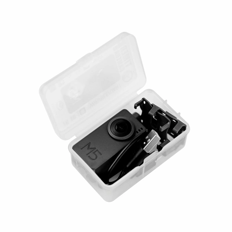
Includes
- 1 x TimerCamera-F
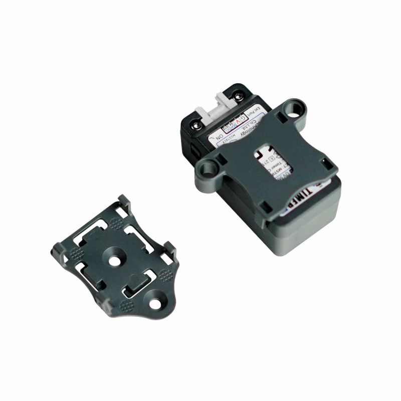
- 1 x LEGO Adapter
- 1 x Wall-1515
- 1 x USB Type-C cable (20cm)
Applications
- Timed photo capture
- Remote monitoring
Specifications
| Specification | Parameter |
|---|---|
| PSRAM | 8MB Quad |
| Flash | 4M |
| Battery | 270mAh |
| Image Sensor | OV3660 |
| Maximum Resolution | 3MP |
| Output Format | 8-/10-Bit RAW, RGB and YCbCr output, compression. |
| DFOV | 120° |
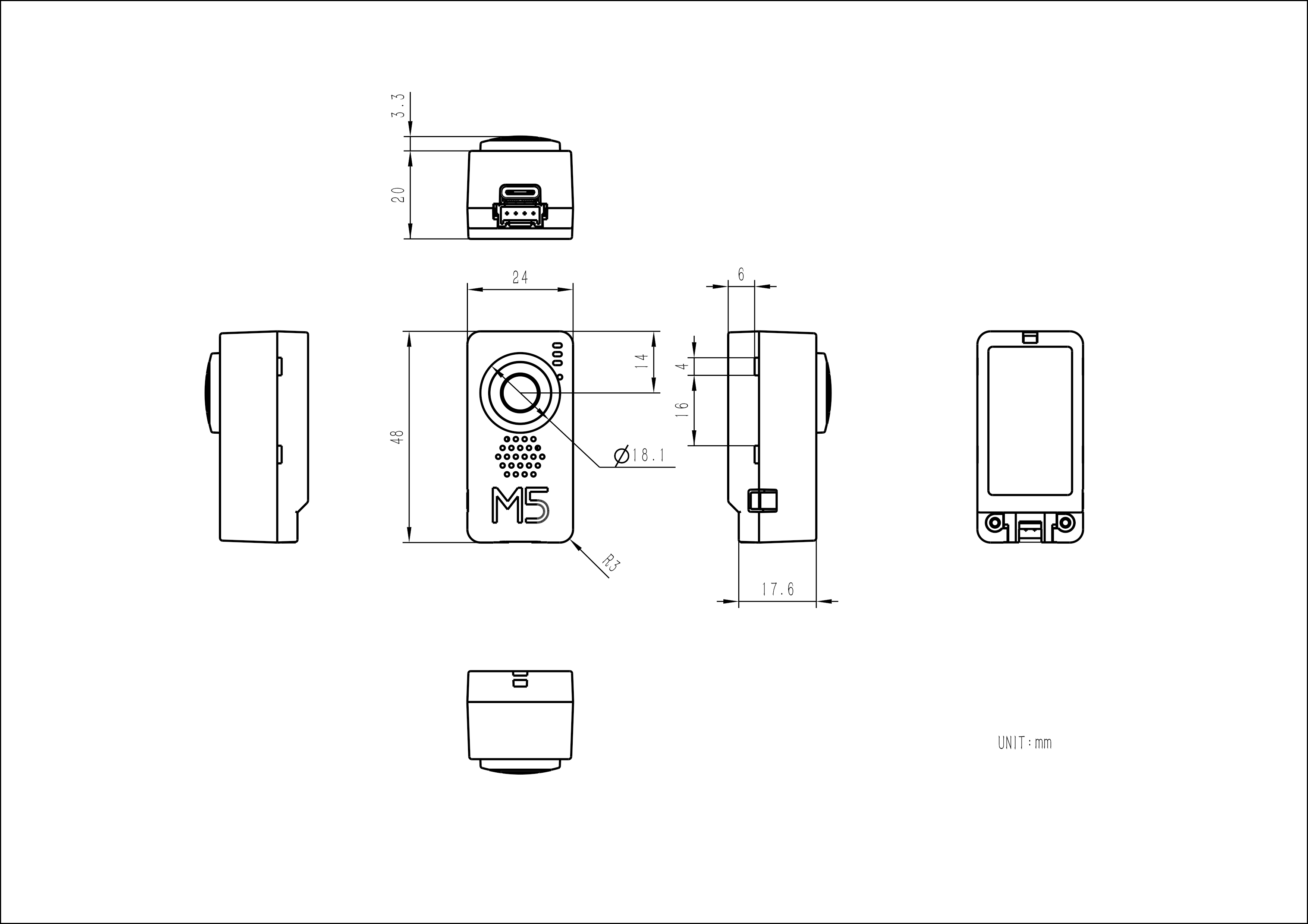
| Product Size | 48.0 x 24.0 x 23.3mm |
| Product Weight | 21.4g |
| Package Size | 75.0 x 46.0 x 30.0mm |
| Gross Weight | 43.8g |
Learn
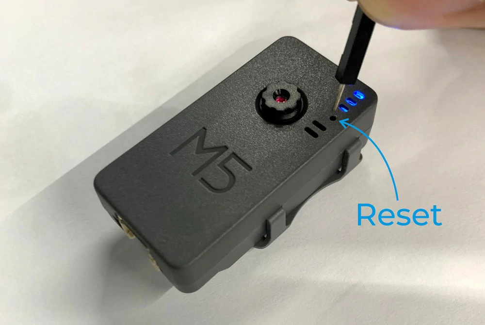
The Timer Camera series uses a low-power power management solution different from CORE and StickC devices. When in use, the PWR button is used as the power button (press and hold for 2s). To turn off the device, you need to use the software API or press the reset button on the PCB. When using external power, the device will remain powered on.
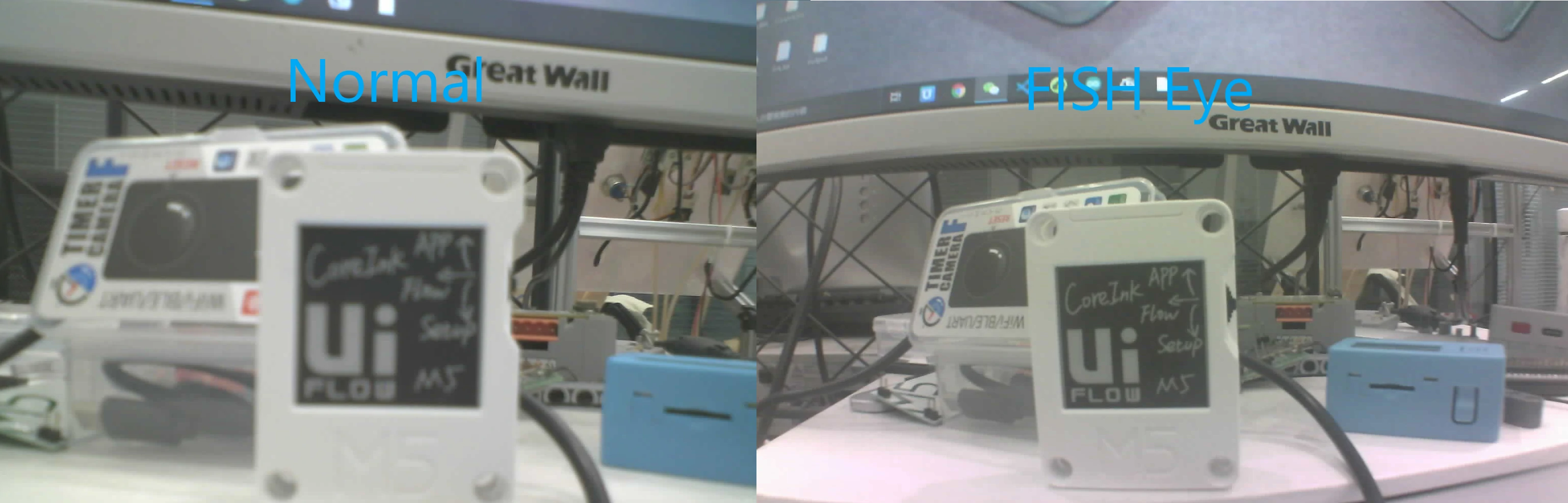
Fisheye Lens vs. Standard Lens Imaging Comparison
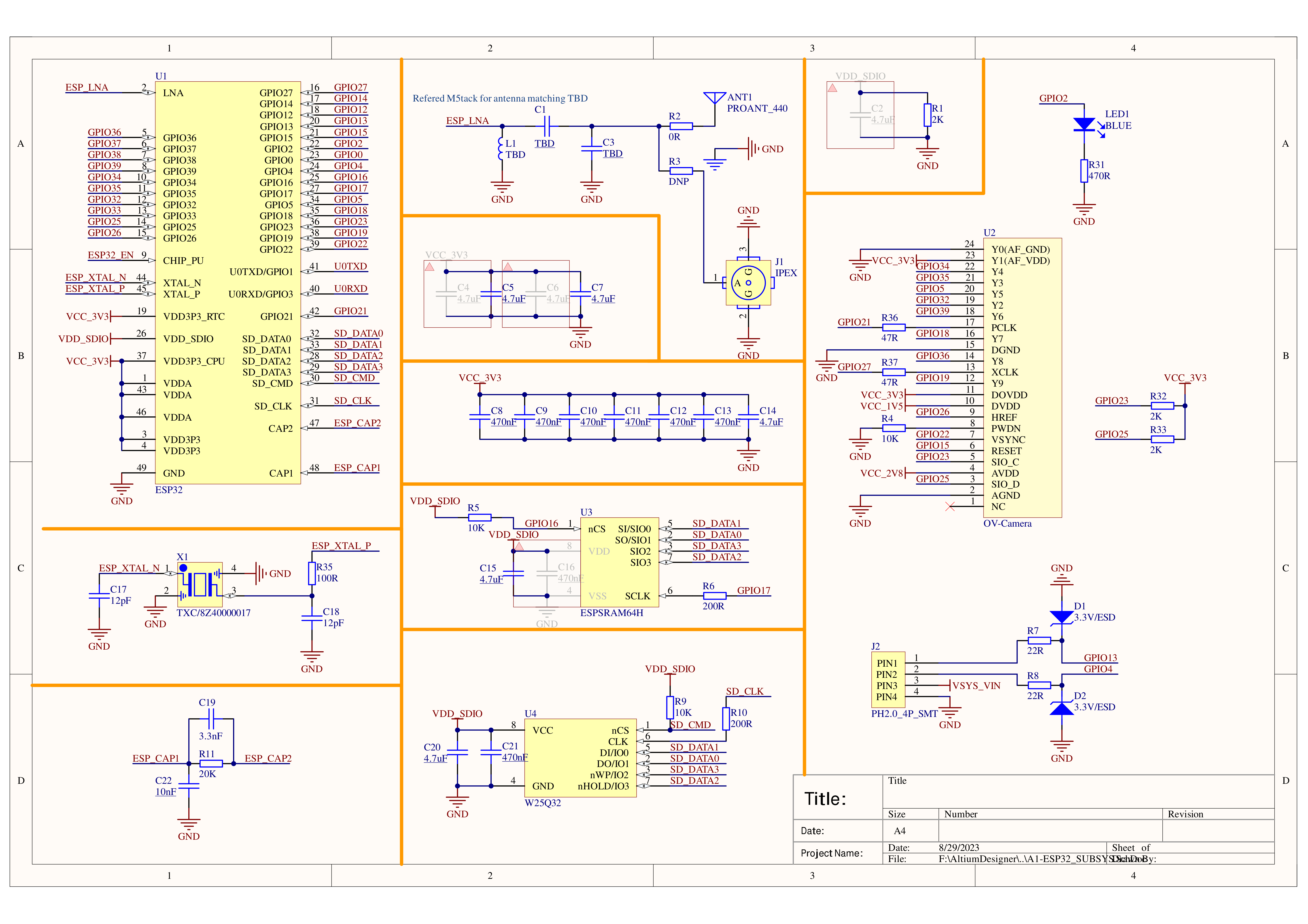
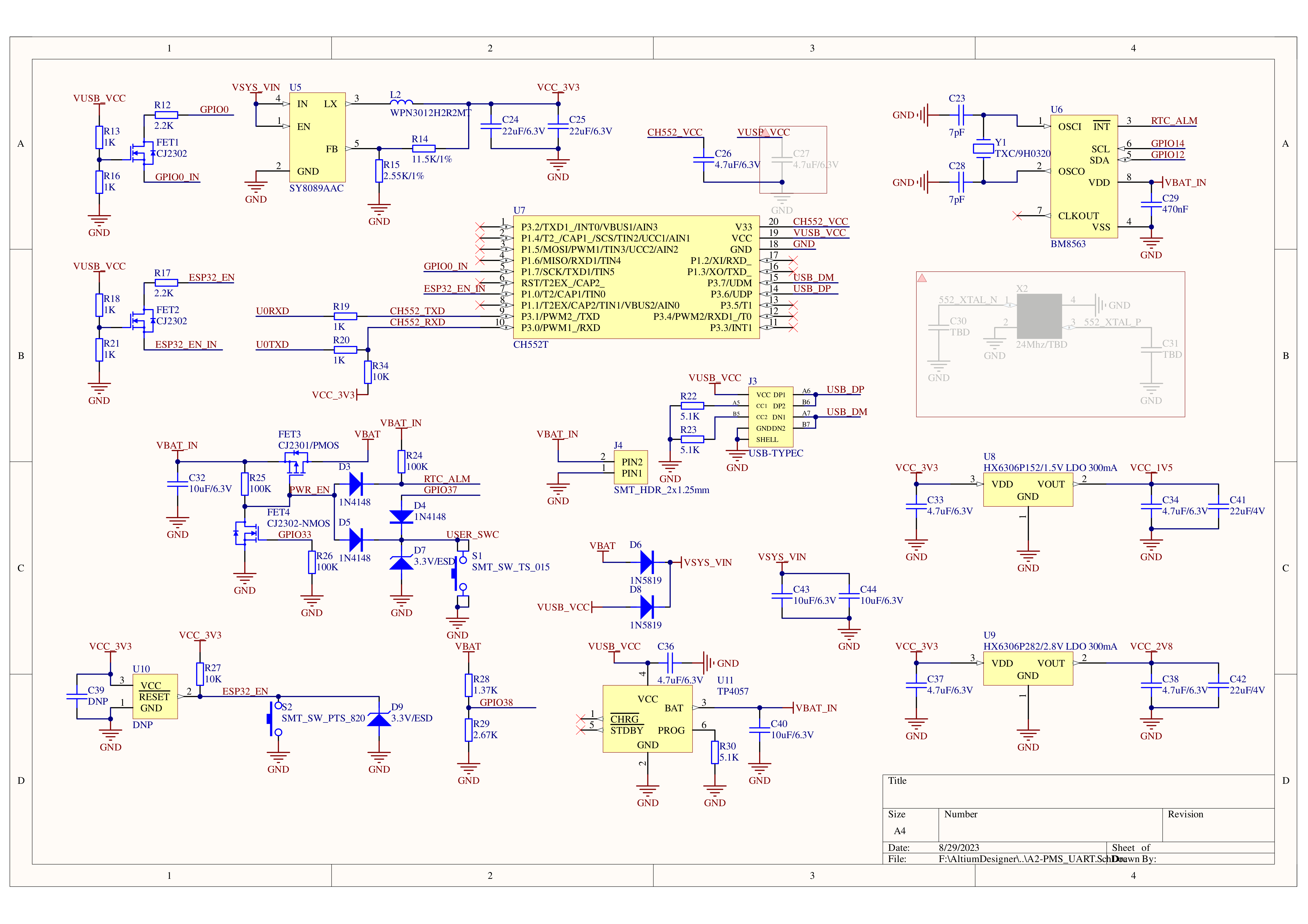
Schematics
PinMap
OV3660
| Interface | Camera Pin | TimerCamera |
|---|---|---|
| SCCB Clock | SIOC | G23 |
| SCCB Data | SIOD | G25 |
| System Clock | XCLK | G27 |
| Vertical Sync | VSYNC | G22 |
| Horizontal Reference | HREF | G26 |
| Pixel Clock | PCLK | G21 |
| Pixel Data Bit 0 | D0 | G32 |
| Pixel Data Bit 1 | D1 | G35 |
| Pixel Data Bit 2 | D2 | G34 |
| Pixel Data Bit 3 | D3 | G5 |
| Pixel Data Bit 4 | D4 | G39 |
| Pixel Data Bit 5 | D5 | G18 |
| Pixel Data Bit 6 | D6 | G36 |
| Pixel Data Bit 7 | D7 | G19 |
| Camera Reset | RESET | G15 |
| Camera Power Down | PWDN | -1 |
| Power Supply 3.3V | 3V3 | 3V3 |
| Ground | GND | GND |
HY2.0-4P
| HY2.0-4P | TimerCamera |
|---|---|
| SCL | G13 |
| SDA | G4 |
| 5V | 5V |
| GND | GND |
LED
| LED | TimerCamera |
|---|---|
| LED_Pin | G2 |
BM8563
| BM8563 | TimerCamera |
|---|---|
| SCL | G14 |
| SDA | G12 |
BAT
| BAT | TimerCamera |
|---|---|
| BAT_ADC_Pin | G38 |
| BAT_HOLD_Pin | G33 |
Datasheets
Model Size
Softwares
Quick Start
- Camera-Tool Guide
- UIFlow-Media Trans
- UIFlow-UART/TIMER
- Arduino Quick Start
- Timer Folder Pusher
- Timer Amazon S3 Folder Pusher
Arduino
ESP-IDF
Home Assistant
Undervoltage/Power Loss Protection
ESP-IDF
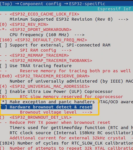
ESP-IDF can be configured in menuconfig during project compilation to disable this feature.
idf.py menuconfigComponent config->ESP32-specific->Hardware brownout detect & reset (disable)
Arduino
On the Arduino platform, you can disable this feature during initialization with the following example code.
#include "soc/soc.h"
#include "soc/rtc_cntl_reg.h"

void setup() {
  WRITE_PERI_REG(RTC_CNTL_BROWN_OUT_REG, 0); //disable detector
}USB Driver
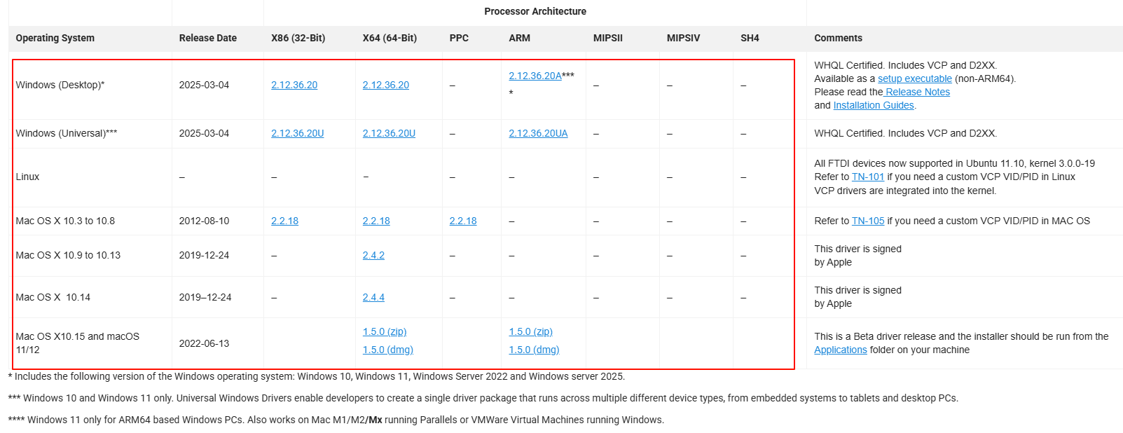
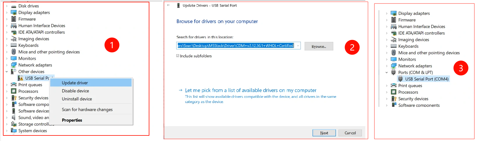
TimerCamera-F may not work driver-free on some systems. Users can manually install the FTDI VCP driver to resolve this issue. Taking Windows 10 as an example, download the driver file that matches your operating system and extract it. Then, install it via Device Manager. (Note: In certain system environments, you may need to install the driver twice for it to take effect. The unrecognized device name is usually M5Stack or USB Serial. For Windows, it is recommended to use Device Manager to install the driver manually (custom update). The executable installation method may not work properly.)
FTDI VCP Driver Download Page:
Installation Method:
EasyLoader
| Easyloader | Download Link | Notes |
|---|---|---|
| TimerCamera-F Firmware Easyloader | download | / |
Video
- Connect to the Unit TimerCAM hotspot, password 12345678, and open 192.168.4.1 in your browser to view the image. For timed photo capture, refer to the Quick Start Guide.
- Focus Adjustment
Product Comparison
To compare information on the TimerCamera series products, you can visit the Product Selection Table, check the target products, and get the comparison results. The selection table covers key information such as core parameters and functional features, and supports comparison of multiple products simultaneously.