


Unit RFID-UHF
SKU:U107
Description
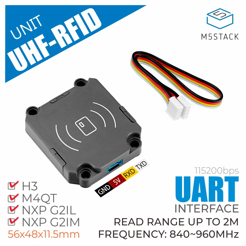
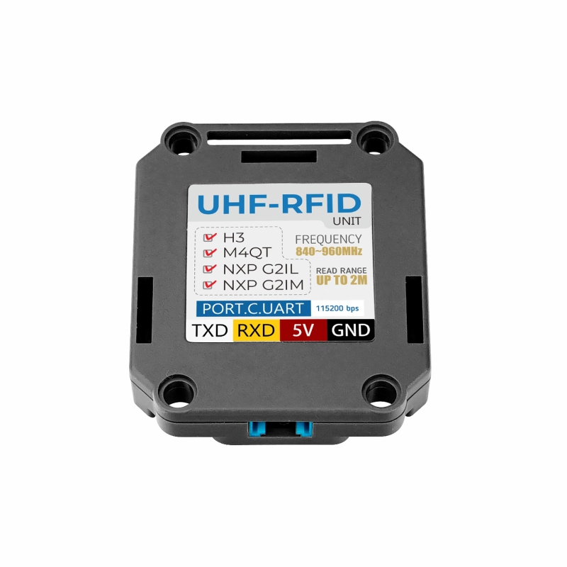
Unit RFID-UHF is an ultra-high frequency (UHF) embedded wireless RF read/write module. It adopts the JRD-4035 module solution with a built-in ceramic antenna, completely eliminating the technical uncertainty caused by the need for an additional antenna in ordinary UHF modules. The optimized RF design achieves low power consumption and high performance, reaching an effective range of over 1.5M with just 100mW transmission power. Using a serial communication interface along with a built-in package of AT command sets, it achieves plug-and-play functionality, providing a good development and usage experience. It is suitable for scenarios such as warehouse logistics management and smart retail, meeting the needs of monitoring and reading multiple product tags.
Features
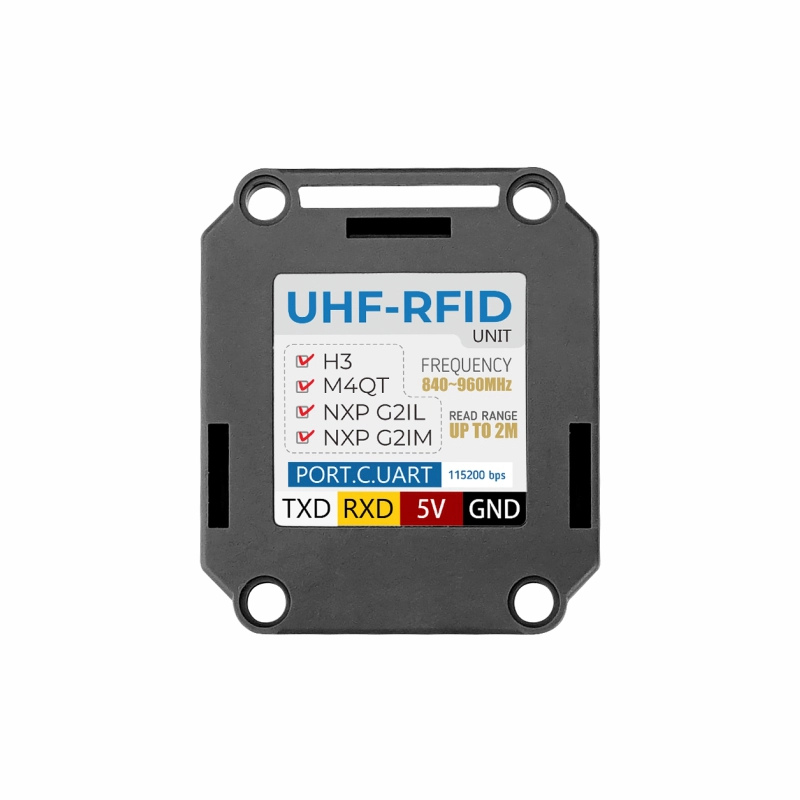
- Detection range: up to 2M
- Operating frequency range: 840 ~ 960 MHz
- Air interface protocol:
- EPCglobal UHF Class 1 Gen 2
- ISO/IEC 18000-6C
- UART communication interface (baud rate: 115200bps)
- Buffer capacity up to 200 tags
- Sensitive and stable tag recognition
Includes
- 1 x Unit RFID-UHF
- 1 x HY2.0-4P Grove Cable (20cm)
- 1 x RFID Tag (840 ~ 960 MHz)
Applications
- Warehouse logistics pallet management
- Vehicle management
- Smart retail
Specifications
| Specification | Parameter |
|---|---|
| Air Interface Protocol | EPCglobal UHF Class 1 Gen 2 ISO/IEC 18000-6C |
| Supported Regions | United States, Canada and other regions following FCC Europe and other regions following ETSI EN 302 208 Mainland China, Taiwan, Japan, Korea, Malaysia |
| Operating Frequency Range | 840 ~ 960 MHz |
| Output Power Range | 18 ~ 26 dBm |
| Tag Buffer | 200 tags |
| Communication Protocol | UART (baud rate: 115200bps) |
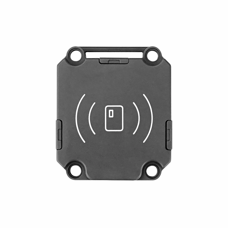
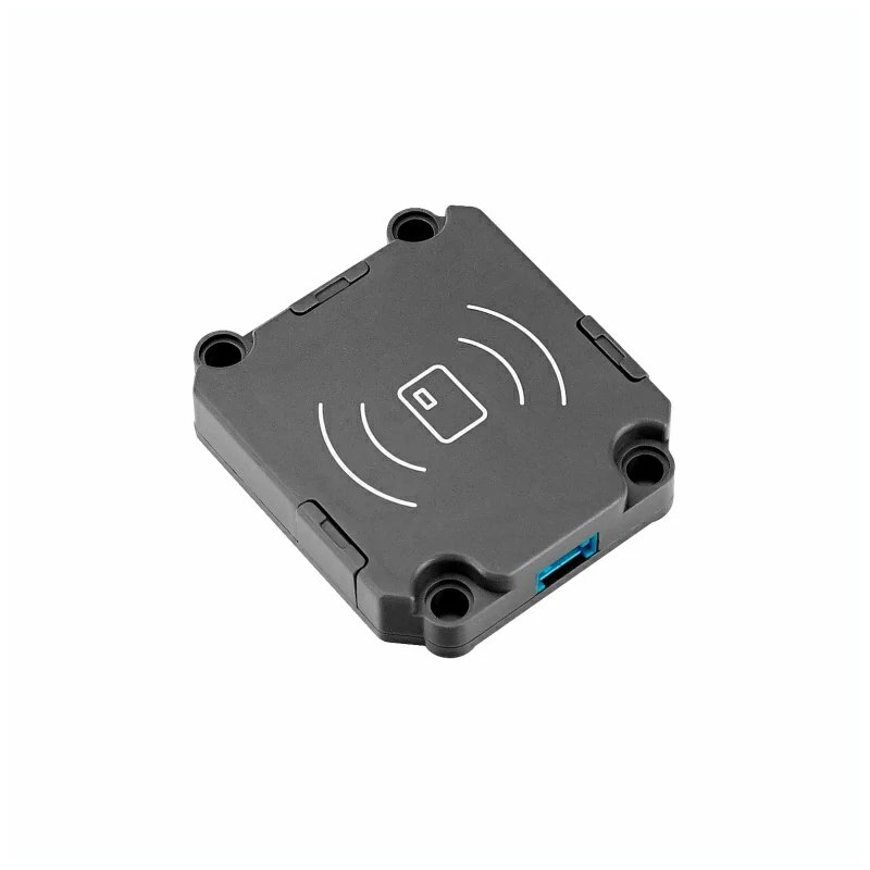
| Shell Material | Plastic (PC) |
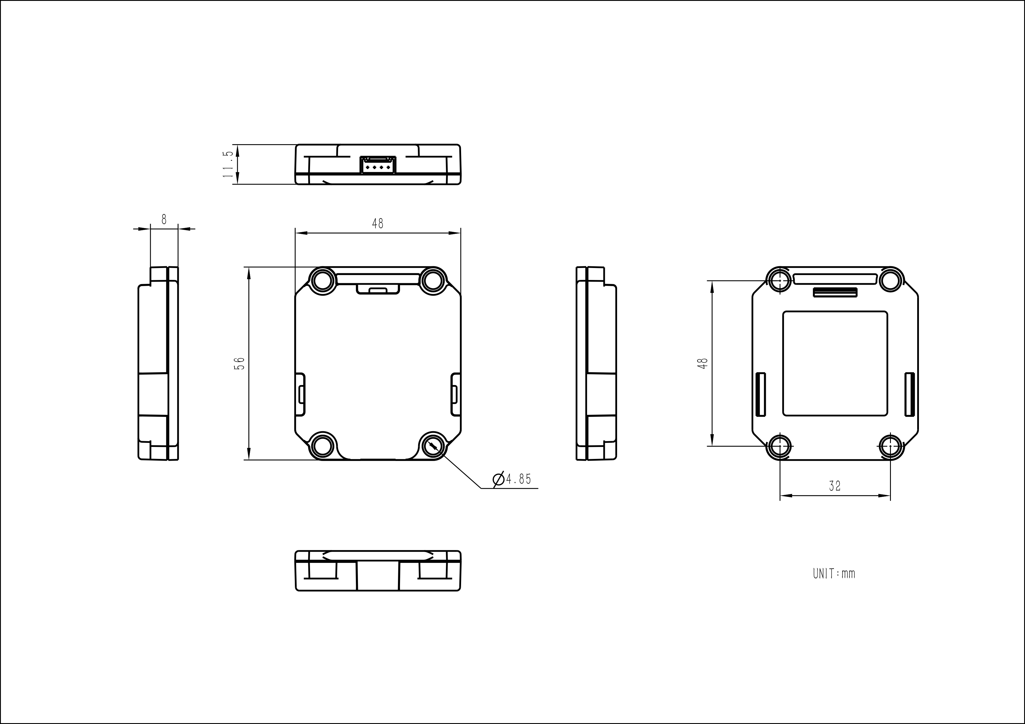
| Product Size | 56.0 x 48.0 x 11.5mm |
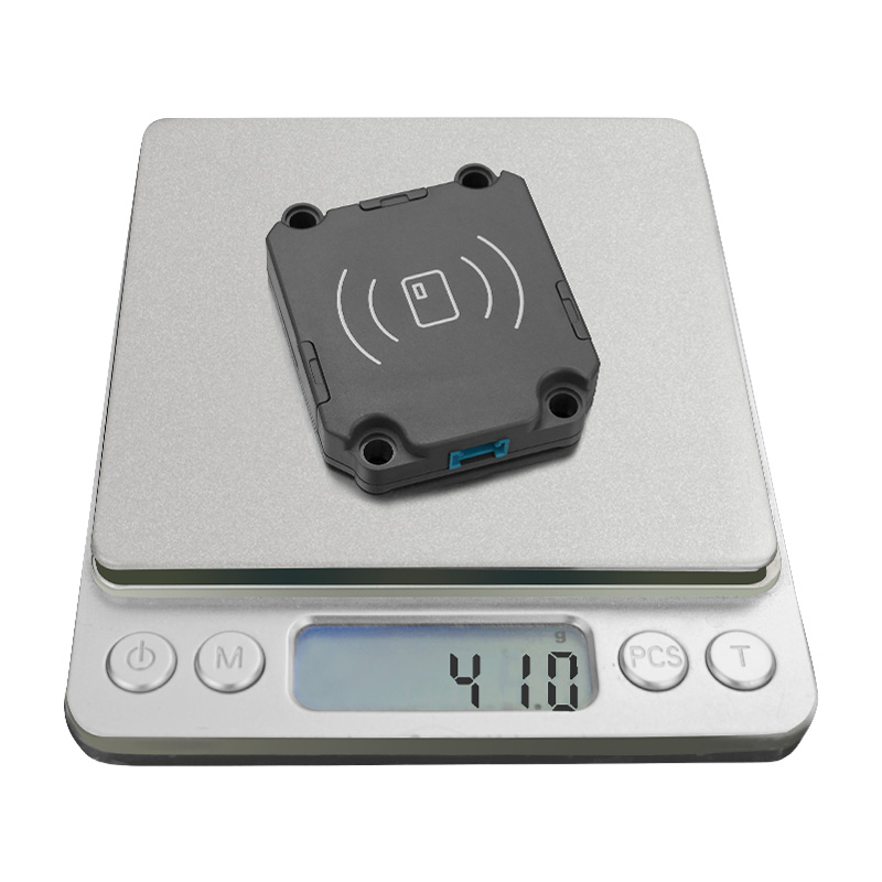
| Product Weight | 41.0g |
| Package Size | 88.0 x 61.0 x 21.0mm |
| Gross Weight | 58.8g |
Learn
Schematics
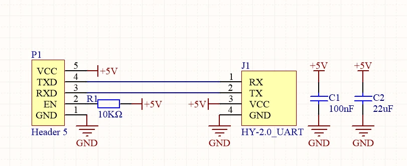
PinMap
Unit RFID-UHF
| HY2.0-4P | Black | Red | Yellow | White |
|---|---|---|---|---|
| PORT.C | GND | 5V | UART_RX | UART_TX |
Model Size
Datasheets
Softwares
Arduino
Protocol
Easyloader
| Easyloader | Download | Note |
|---|---|---|
| Unit RFID-UHF Test Easyloader | download | / |