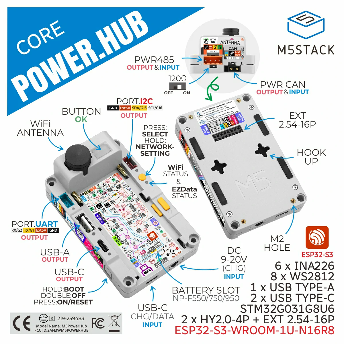
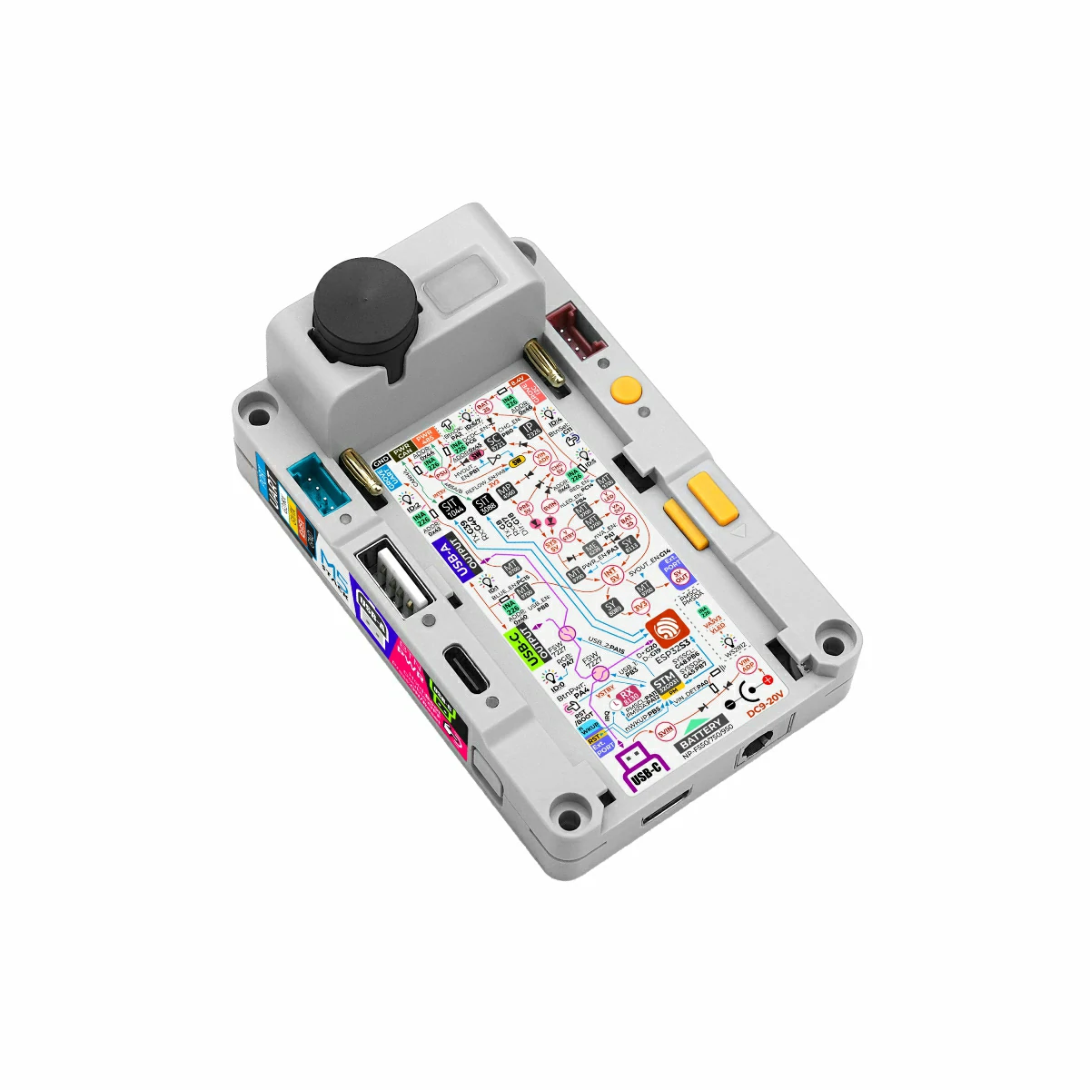
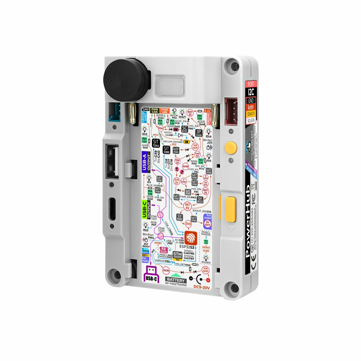
PowerHub is a programmable controller integrating multi-channel power management. It adopts the ESP32-S3-WROOM-1U-N16R8 main control module equipped with a dual-core Xtensa LX7 processor (up to 240MHz), supporting 2.4 GHz Wi-Fi, with 16MB Flash and 8MB PSRAM onboard. A built-in STM32G031G8U6 coprocessor, combined with multiple INA226 voltage/current detection ICs and electronic switch design, enables precise management of power states for multiple expansion interfaces, achieving accurate power consumption control and providing low-power wake-up functionality for the whole device. The USB Type-C port can be used for program download and USB OTG functions. Inside, a USB interface switch allows the bottom USB port to be switched to the front USB Type-A or USB Type-C interface for convenient expansion of USB peripherals. The device features an efficient power management system, supporting multiple power supply modes (DC power + 2S battery power + PWR485/PWR CAN input power). It is equipped with 2x HY2.0-4P Grove ports, RS485, and CAN communication interfaces, facilitating connections to various sensors and industrial control devices. Suitable for industrial automation control, smart home, and other scenarios, it provides developers with stable and reliable IoT solutions.
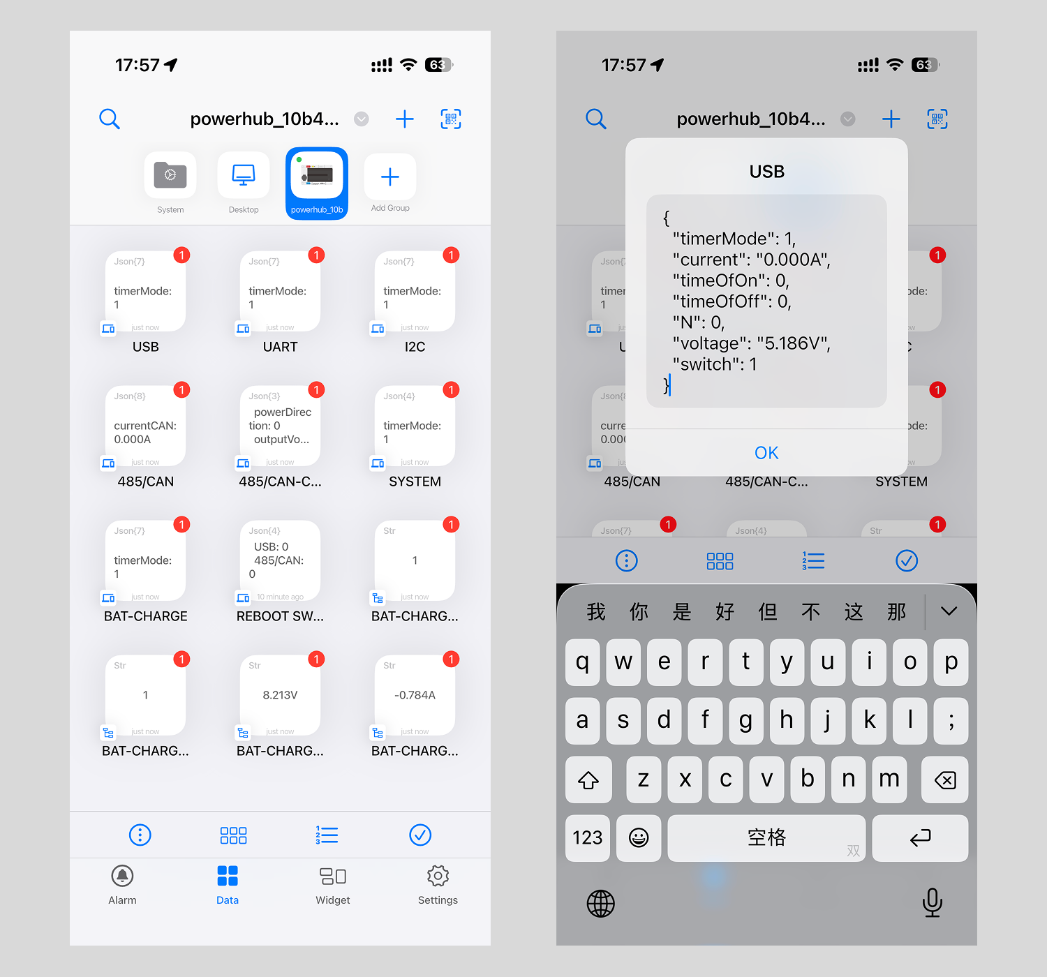
This tutorial introduces the usage of PowerHub's factory firmware, including button operations, controlling interface on/off through the EZData app or web page, and methods for monitoring voltage and current data.
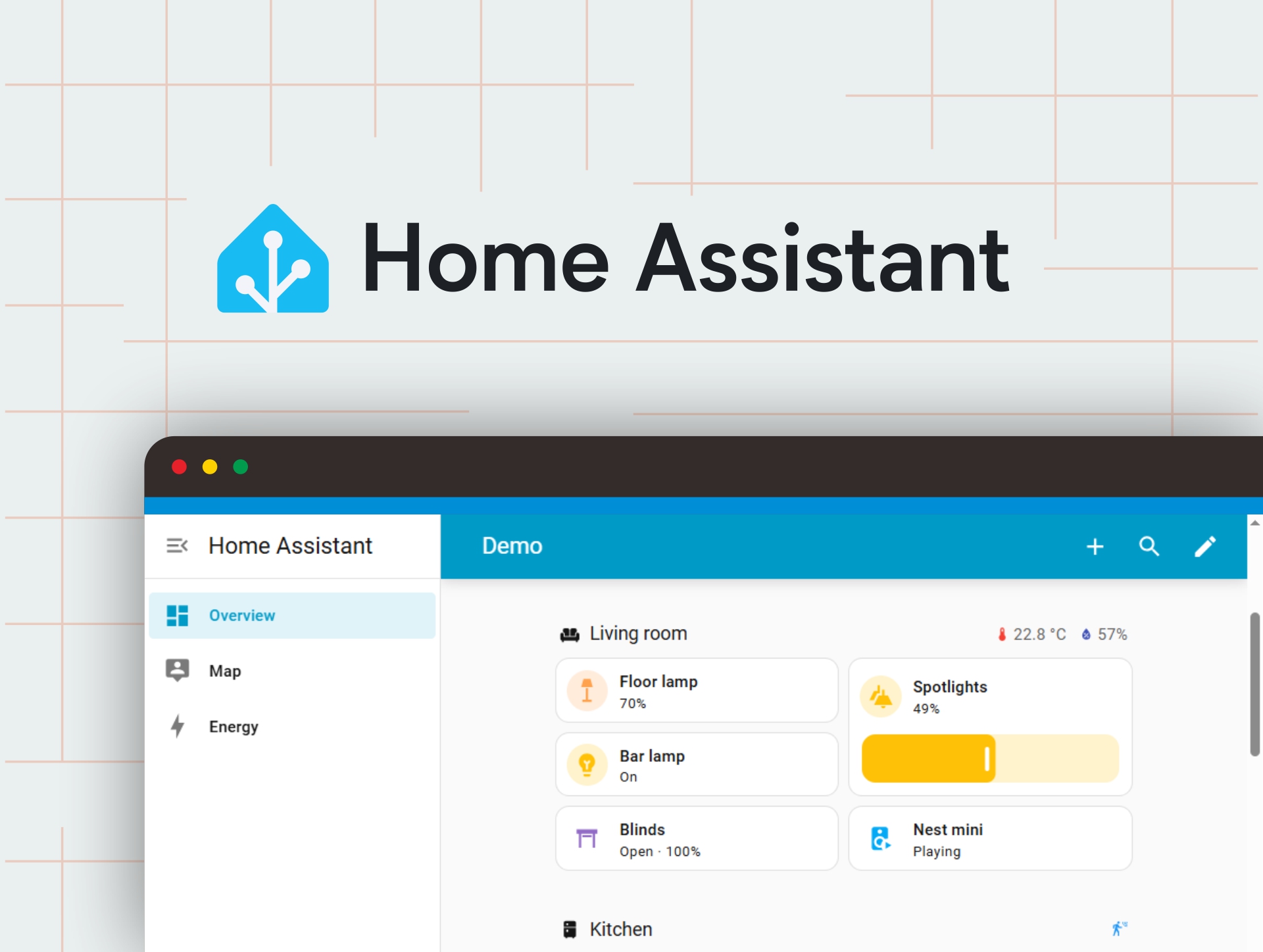
This article shows how to add PowerHub into your Home Assistant
Features
ESP32-S3-WROOM-1U-N16R8 main control core
Supports low-power timed wake-up
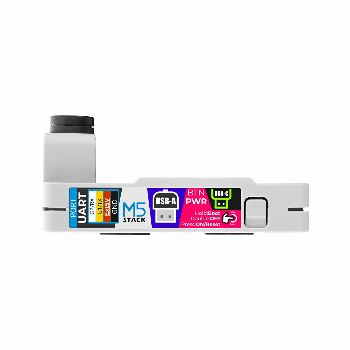
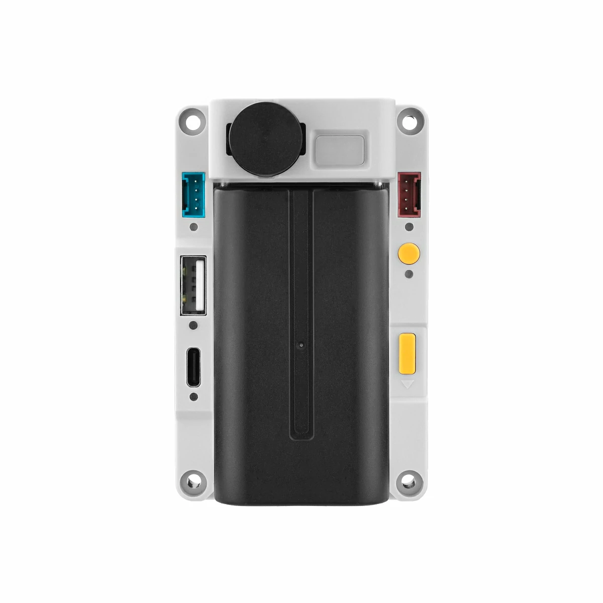
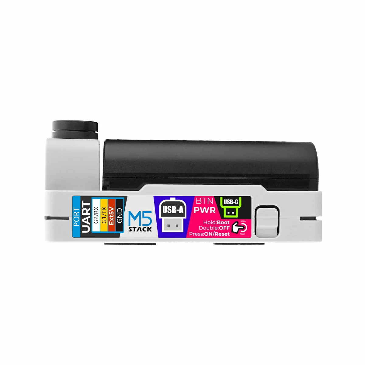
USB Type-A / USB Type-C expansion interfaces
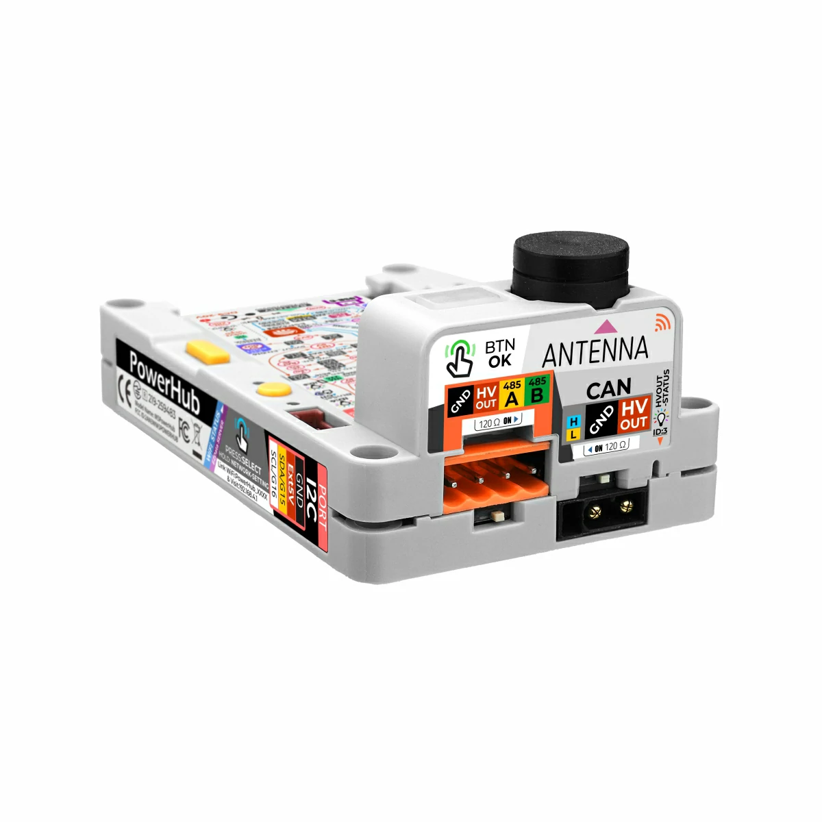
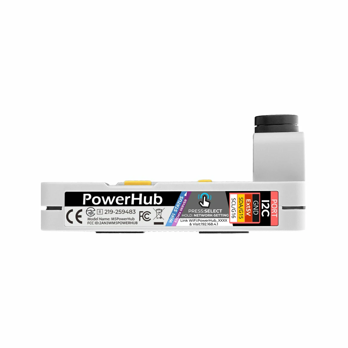
2 x HY2.0-4P expansion ports
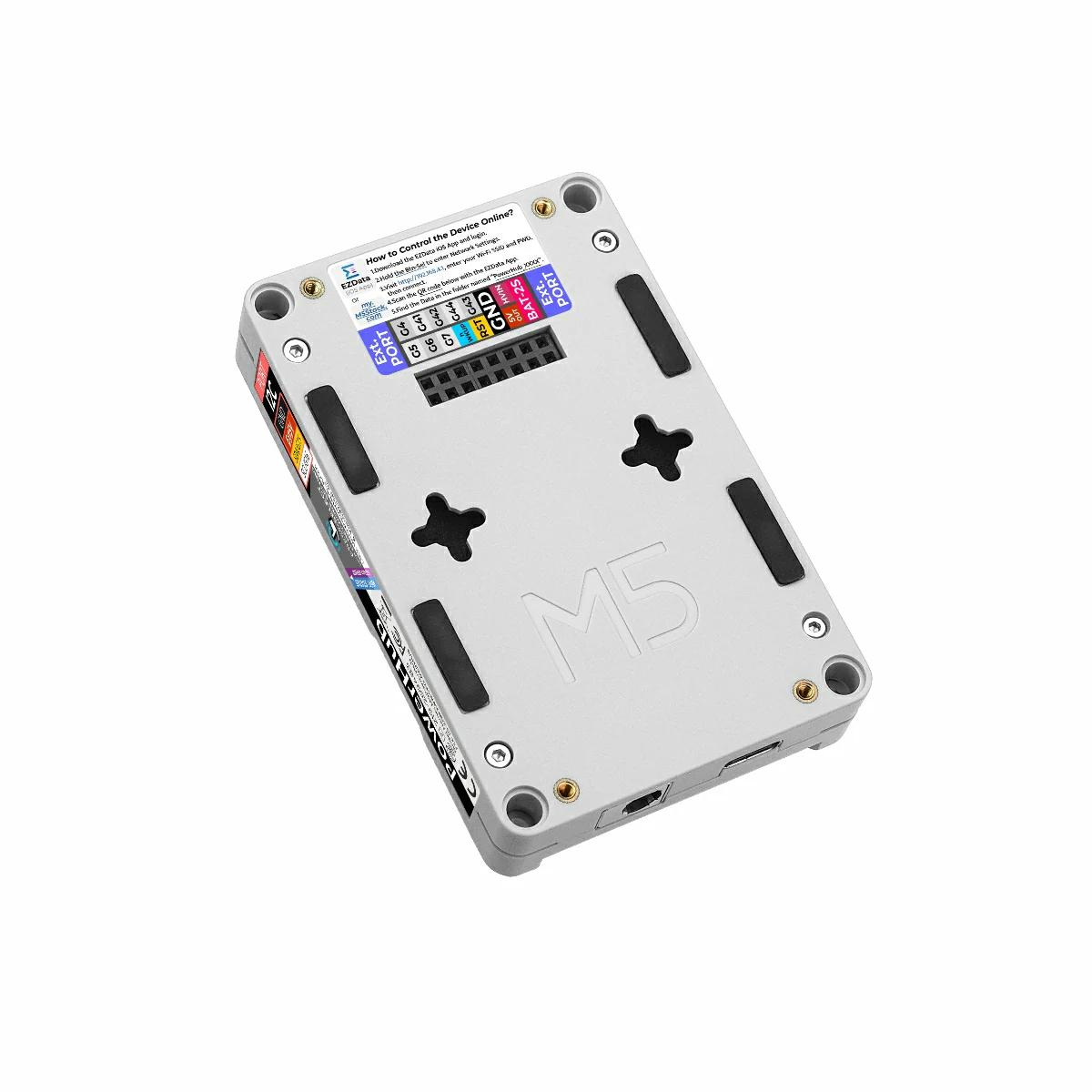
2.54-16P expansion bus interface
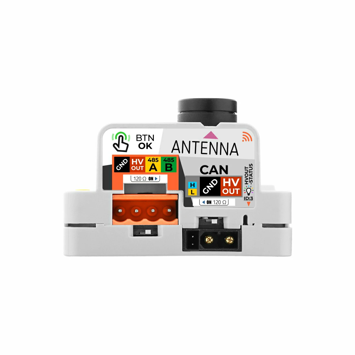
RS485 communication interface (with built-in 120Ω terminal resistor switch)
CAN bus communication interface (with built-in 120Ω terminal resistor switch)
2.4 GHz SMA mini antenna
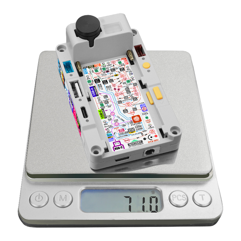
Multiple power supply modes:
PWR485/PWR CAN input power
2S battery power supply
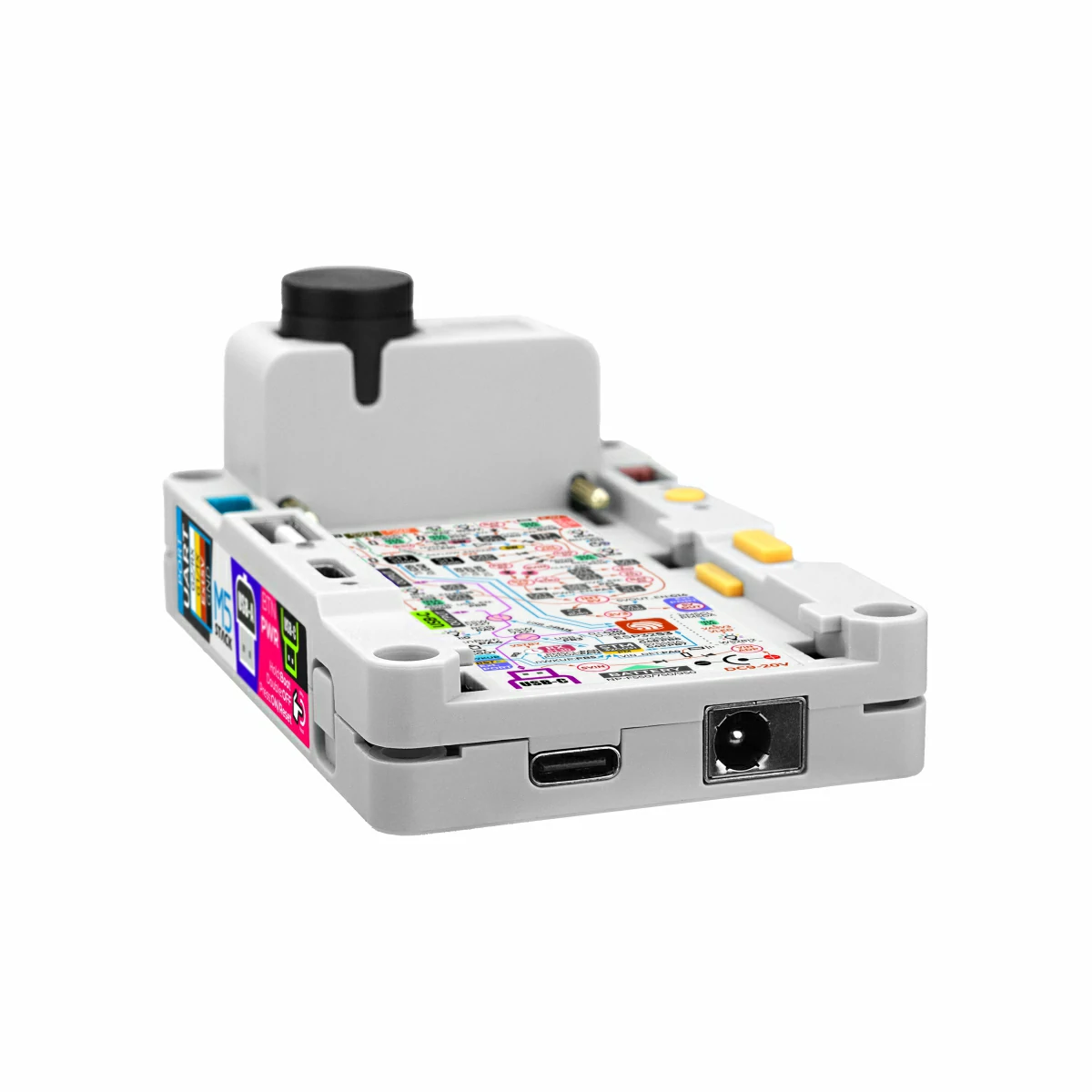
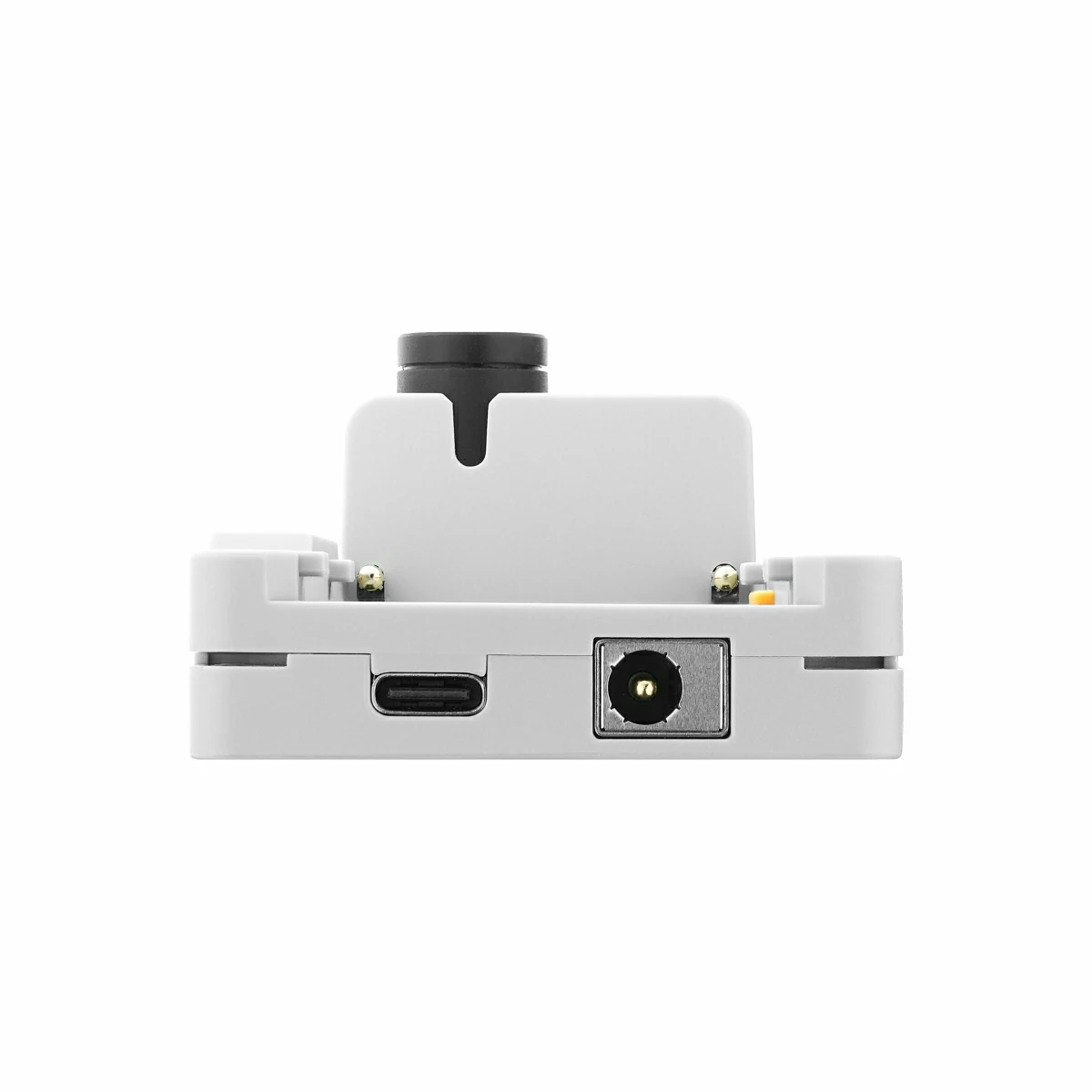
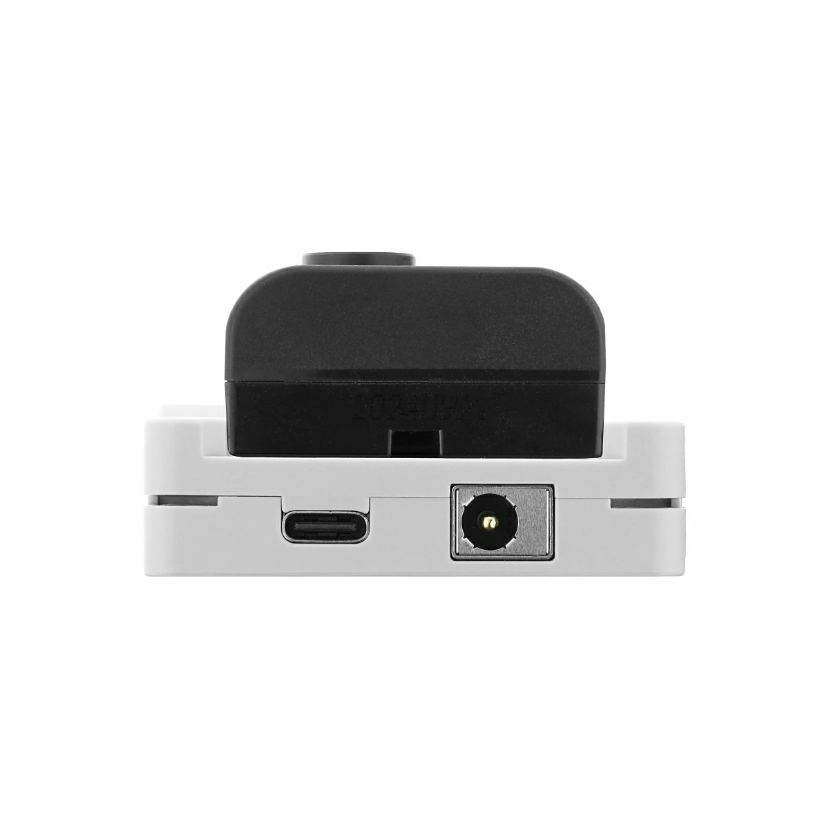
DC 9 ~ 20V power supply
Human-machine interaction:
Multi-channel status indicator lights
3 x physical buttons
Multiple mounting methods:
Magnetic design for mounting on metal surfaces
Rear cross mounting holes for wall installation
Lego mounting holes
M2 screw holes
Includes
Product Note
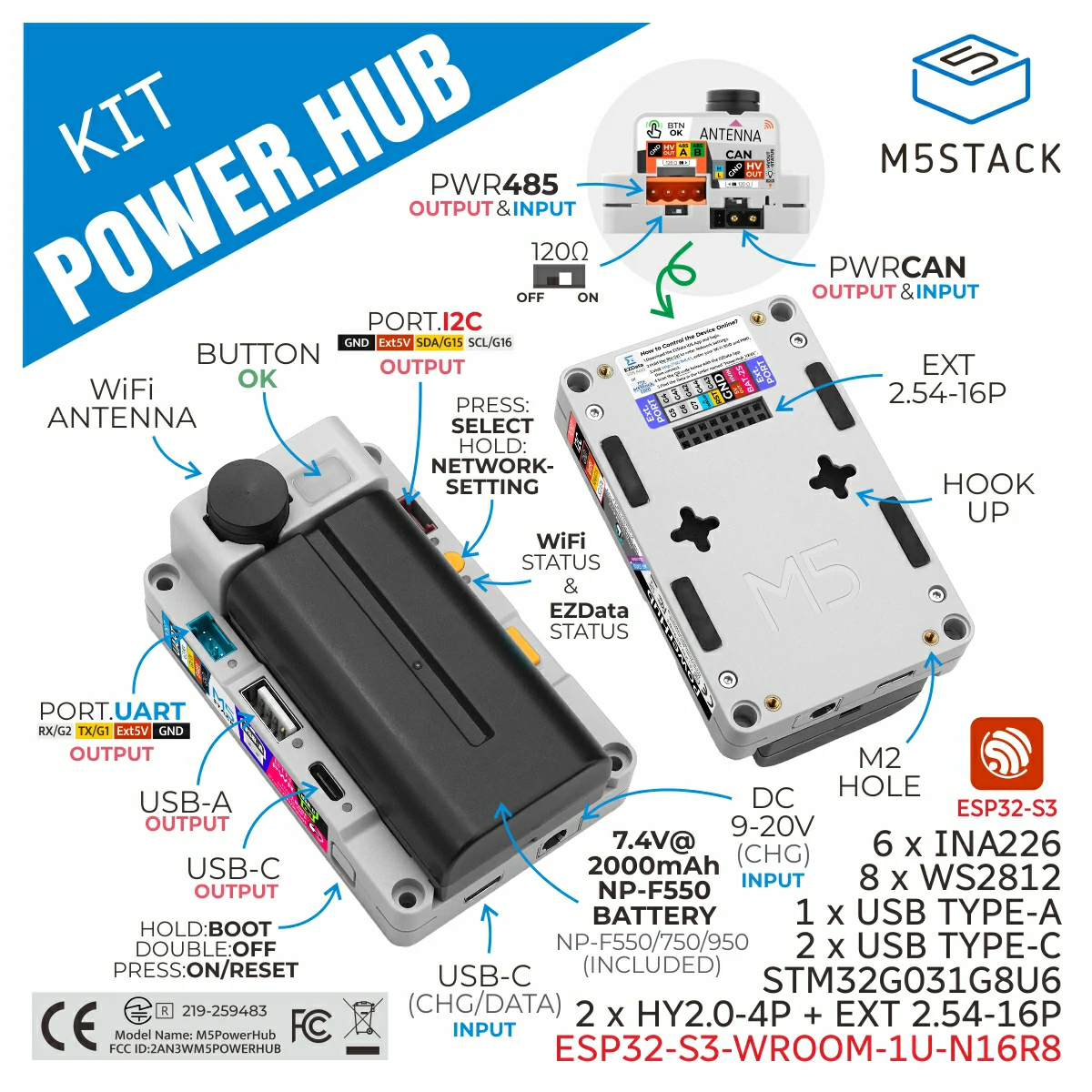
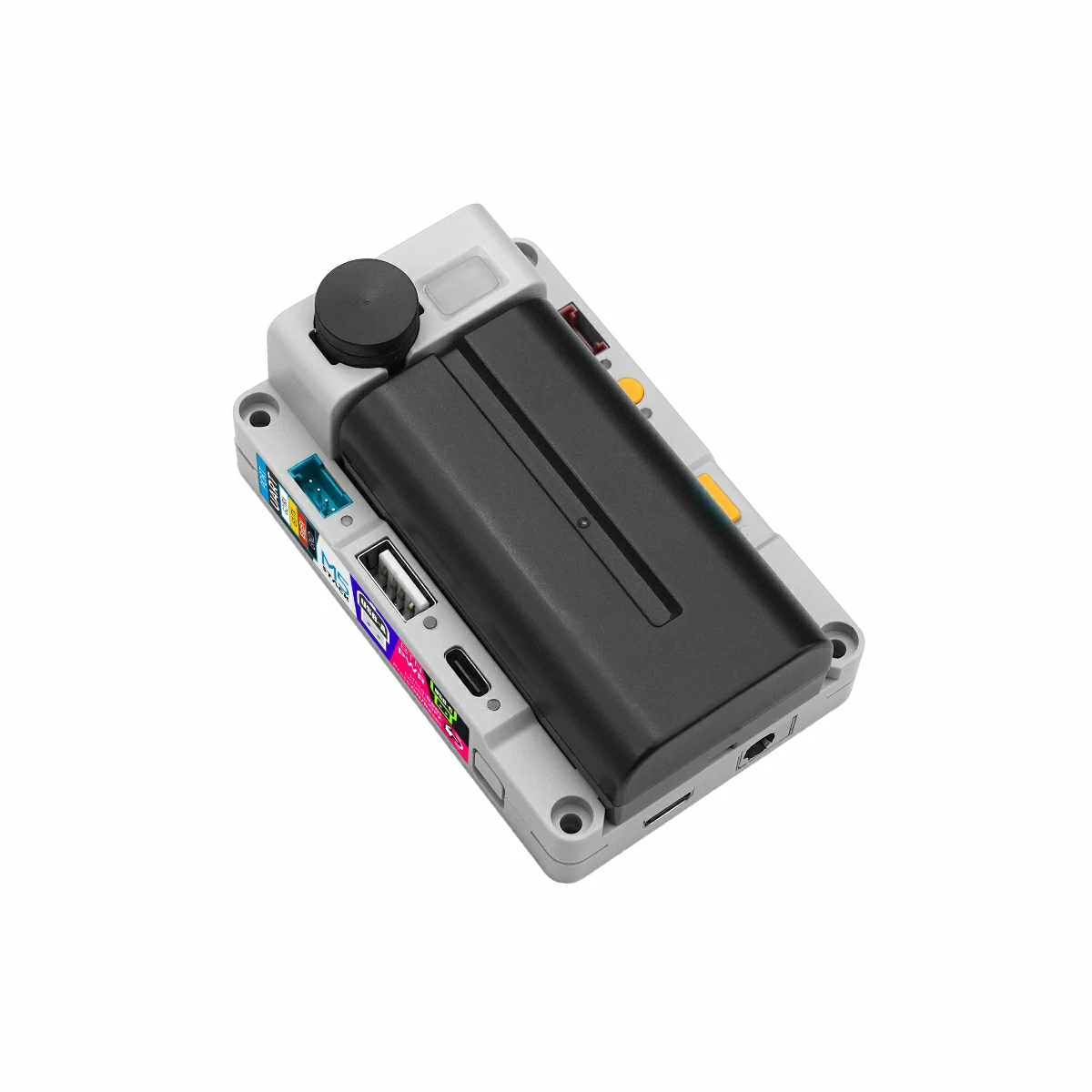
The PowerHub Kit is an integrated set equipped with a removable NP-F550 lithium battery, while the standard PowerHub does not include a battery and requires an external power source or separate battery purchase.
PowerHub (SKU:C148)
1 x PowerHub
PowerHub Kit (SKU:K148)
1 x PowerHub
1 x NP‑F550 2000mAh removable battery
Applications
Industrial automation
Smart home
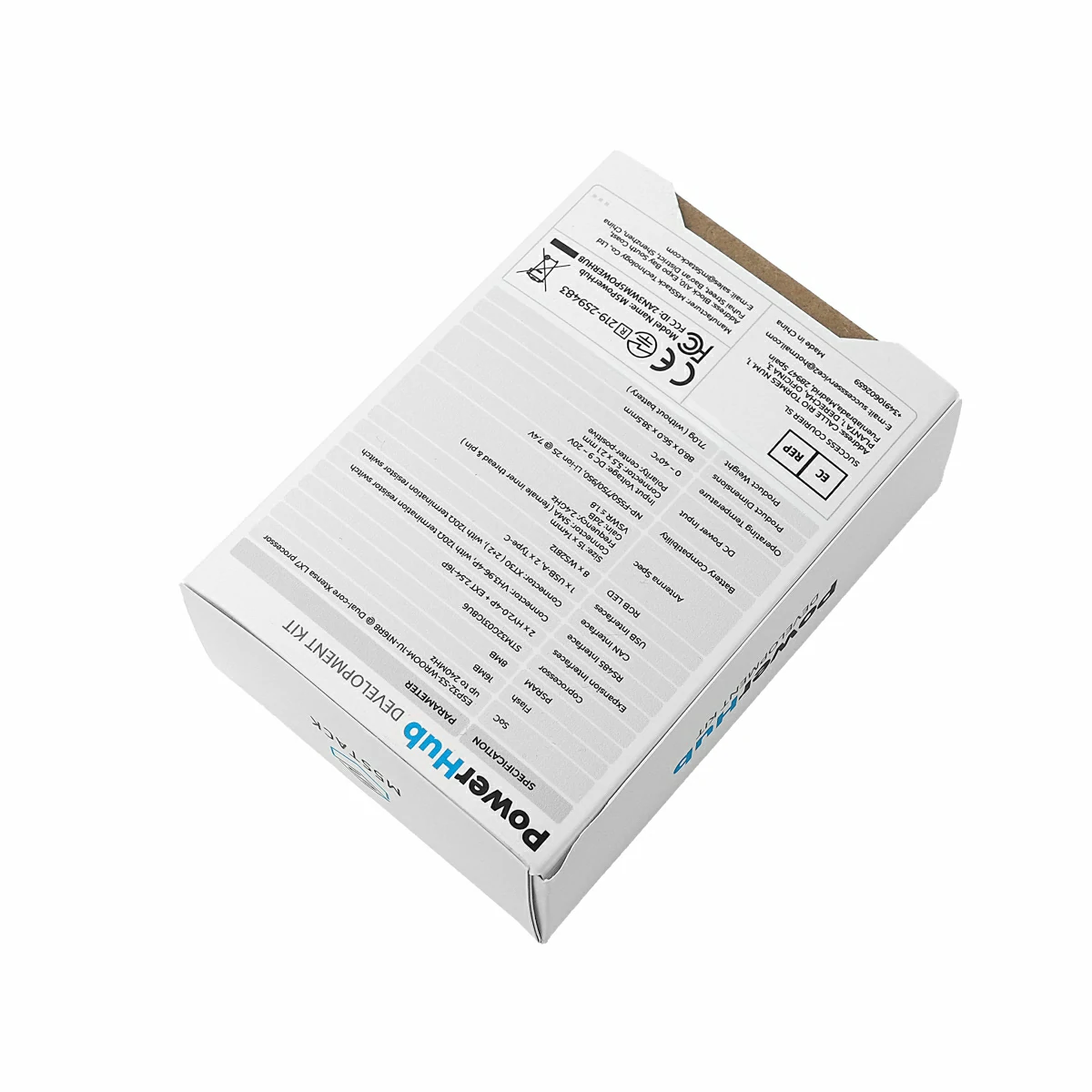
Specifications
Specification
Parameter
SoC
ESP32-S3-WROOM-1U-N16R8@Dual-core Xtensa LX7 processor, up to 240MHz
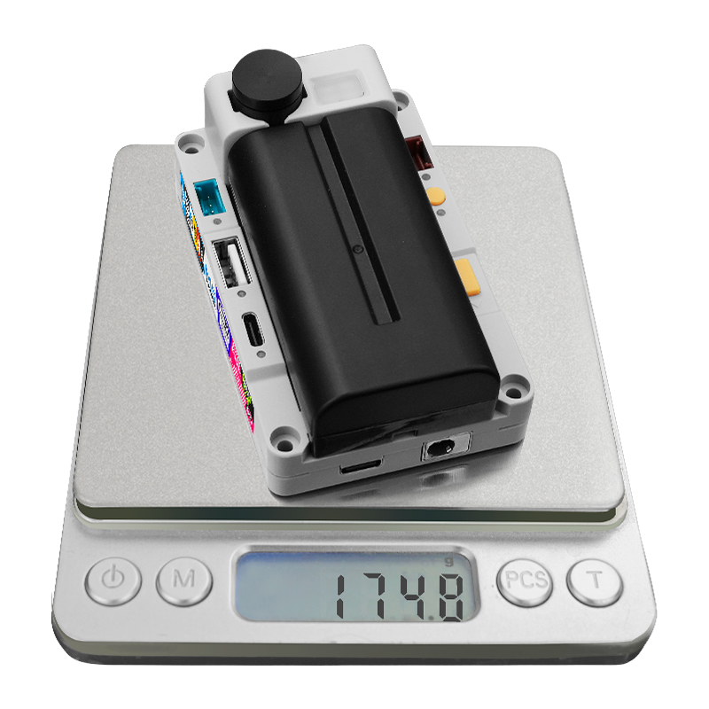
Connect the device to the computer using a USB-C data cable, press and hold the side BtnPWR button for 3 seconds until the indicator light next to the black antenna flashes blue multiple times. At this point, the device enters download mode.
Charging Instructions
Charging Instructions
When the battery is over-discharged and its voltage drops below 6V, it enters protection mode. Before recharging, remove the battery, reset the device, reinstall it, and then charge via the device’s USB Type-C port. During the initial charging phase, since the battery is still in protection mode, the charging chip trickle-charges with a small current. This state lasts several minutes, depending on the battery voltage level. Once the voltage rises above 6V, the chip automatically switches to normal charging mode.
PowerHub’s USB interface adopts a two-level switch design:
ESP32-S3 is directly connected to the bottom USB Type-C port of the device.
USB_CON_LV1: Controls ESP32-S3 USB pins connection to the bottom USB Type-C port, or routing to the USB_CON_LV2 switch.
USB_CON_LV2: Controls routing from USB_CON_LV1 to the front USB Type-C port or USB Type-A port.
USB Port Power Supply Note
The bottom USB Type-C port only supports input power, while the front USB Type-C / USB Type-A ports only support output power.
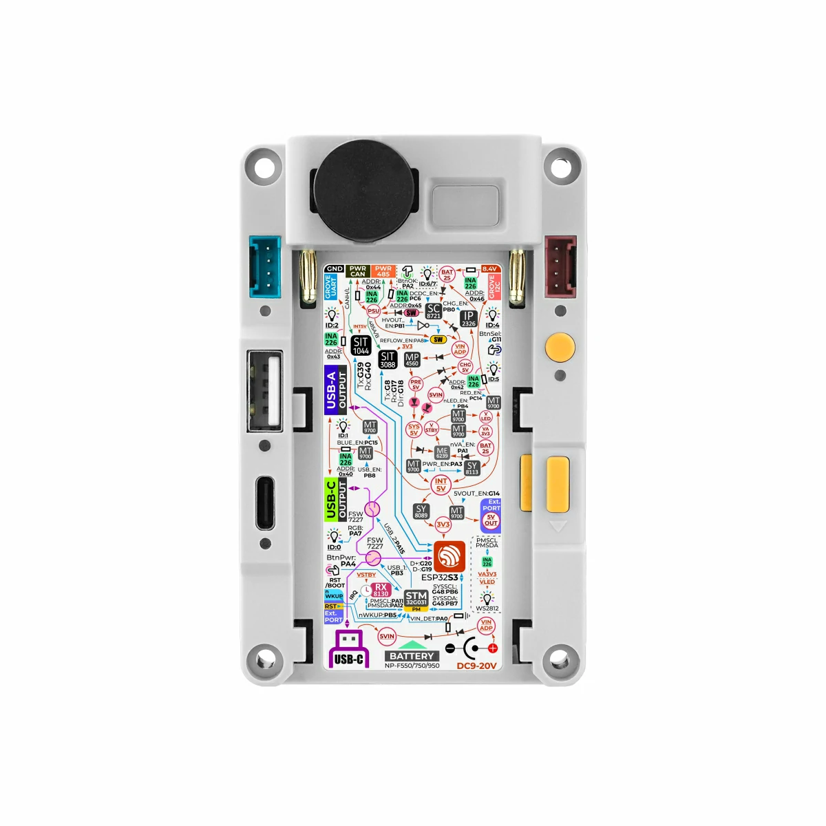
Power Manager
STM32G031
PA12
PA11
INA226(0x40) - USB
PM_SDA
PM_SCL
INA226(0x42) - PORT.A
PM_SDA
PM_SCL
INA226(0x43) - PORT.C
PM_SDA
PM_SCL
INA226(0x44) - PWRCAN
PM_SDA
PM_SCL
INA226(0x45) - PWR485
PM_SDA
PM_SCL
INA226(0x46) - Battery
PM_SDA
PM_SCL
SC8721
PM_SDA
PM_SCL
RX8130CE(0x32)
PM_SDA
PM_SCL
STM32G031
PA1
PA0
PB8
PC14
PC15
PB1
PA8
PC6
INA226_PWR
nVA_EN
DC_INPUT_DETECT
VIN_DET
USB_PWR
OEN_USB
PORT.A_PWR
OEN_GRV_R
PORT.C_PWR
OEN_GRV_B
RS485_CAN_PWR
OEN_PWROUT
PDCDC_REFLOW
SC8721_DCDC_PWR
PDCDC_EN
RS485 & CAN Port Output Power Config
When using the SC8721 buck-boost power supply for forward output, INA226_PWR must be enabled. RS485_CAN_PWR enables OEN_PWROUT for forward output, enables SC8721_DCDC_PWR, and PDCDC_REFLOW must be held low.
RS485 & CAN Port Reverse Power to Main Unit Config
In this mode, disable SC8721, set OEN_PWROUT low, and PDCDC_REFLOW high. This allows external power to backfeed to the host via the PWRCAN or PWR485 ports.