

Home Assistant
Media Player
Expansion
Sensor
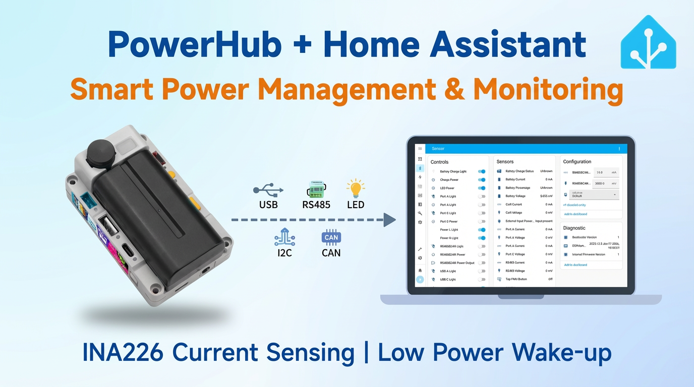
PowerHub Controller Home Assistant Integration
This chapter describes how to integrate PowerHub, a programmable controller with integrated multi-channel power management, into Home Assistant.
Preparation
- Home Assistant Host.
- Install and enable ESPHome Builder in Home Assistant.
Quick Start
Click the button below to flash the firmware with one click. Follow the on-screen instructions to complete the configuration and quickly experience PowerHub integrated with Home Assistant. For one-click flashing and subsequent configuration, please refer to the tutorial.
Note
- In this tutorial, the kit was compiled and uploaded under ESPHome
2025.11.2. If you encounter compilation/upload issues, consider switching ESPHome to this version.
Create Device
Open ESPHome Builder in Home Assistant and create an empty configuration file.
Click the
NEW DEVICEbutton in the bottom right corner.Click
CONTINUEin the pop-up box.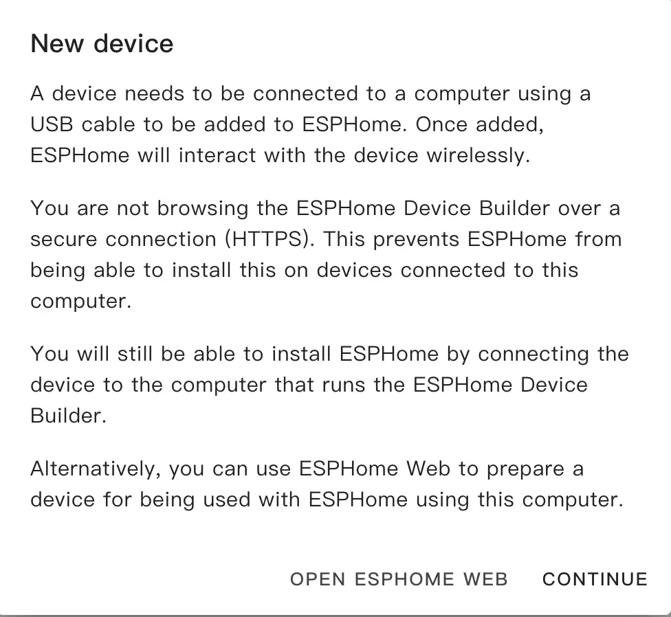
Select
Empty Configuration.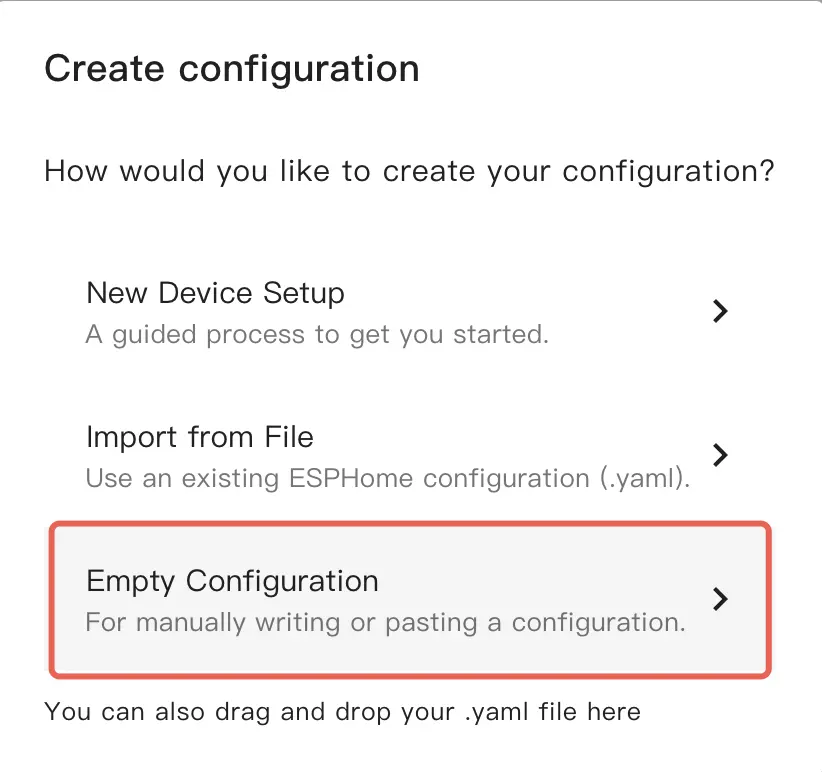
Name the file (Optional).

Click
EDITon the newly generated configuration file.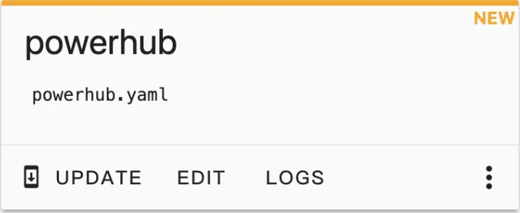
Copy the contents of configurations.yaml into the configuration file.
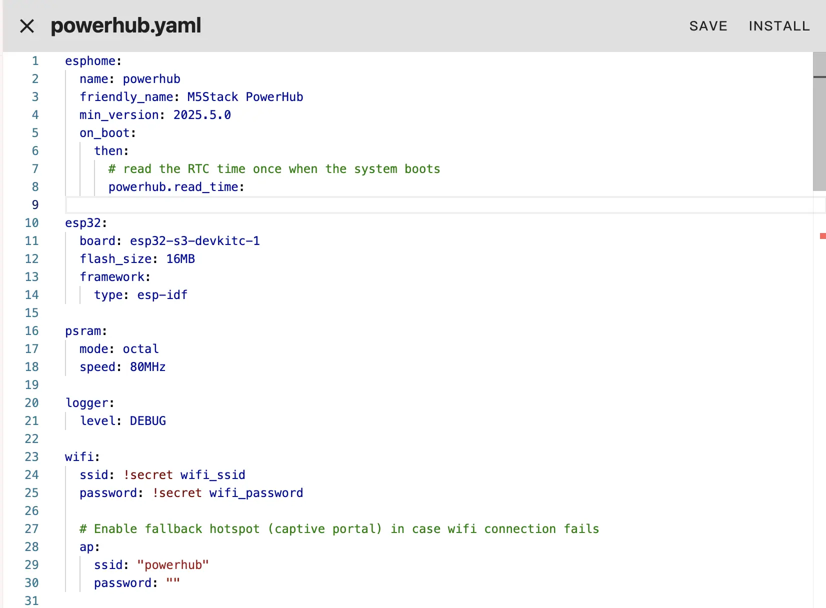
Change network configuration or API information as needed, such as creating an API Encryption Key for authentication:
yaml1 2 3api: encryption: key: "Your_Encryption_Key"
Or change the timezone settings:
timezone: Europe/LondonChange to the appropriate timezone:
timezone: Asia/ShanghaiClick
SAVEandINSTALLin the top right corner in sequence, then selectManual download.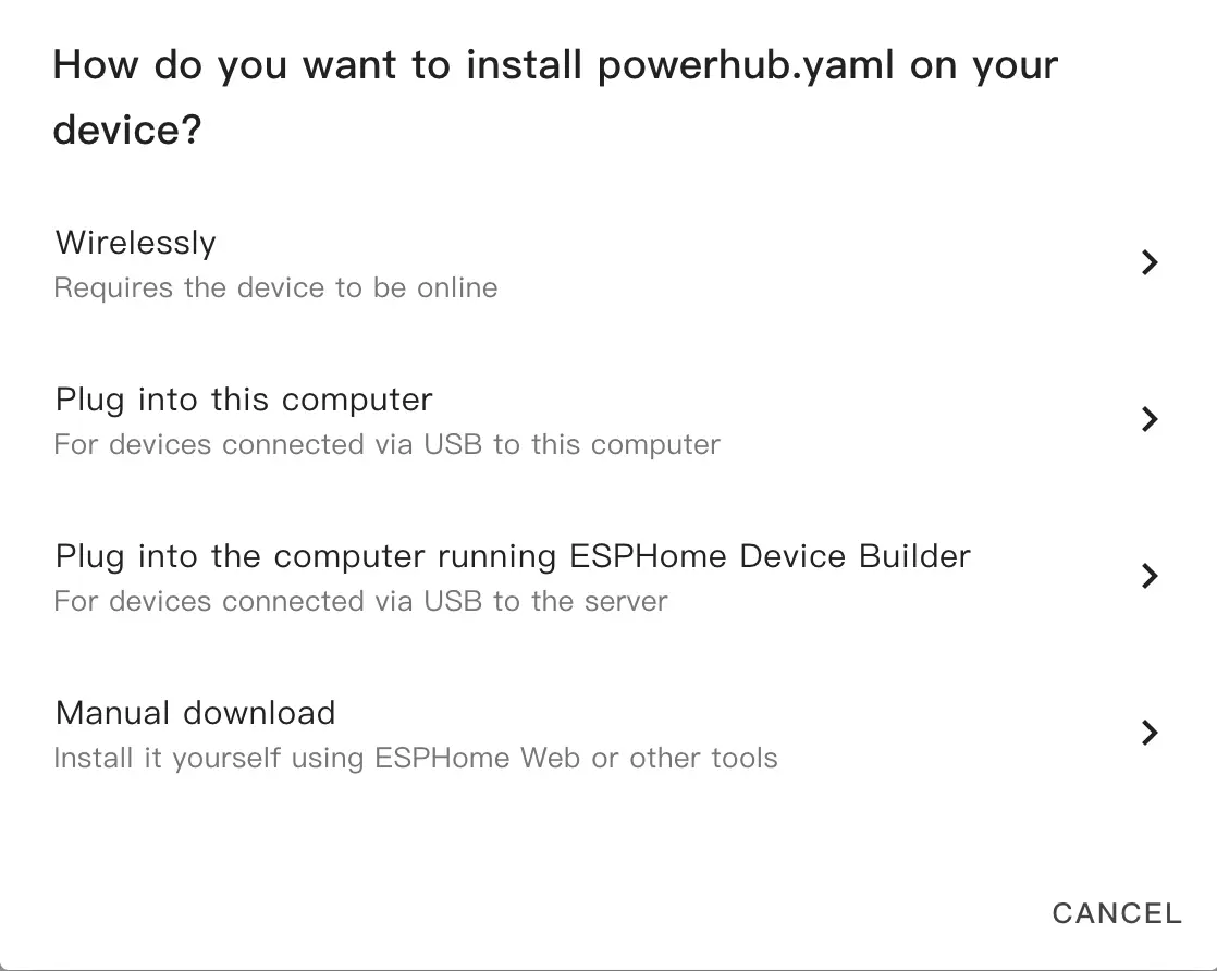
The code will be generated and the project will be compiled.
When compilation is complete, select
Factory formatto download the firmware.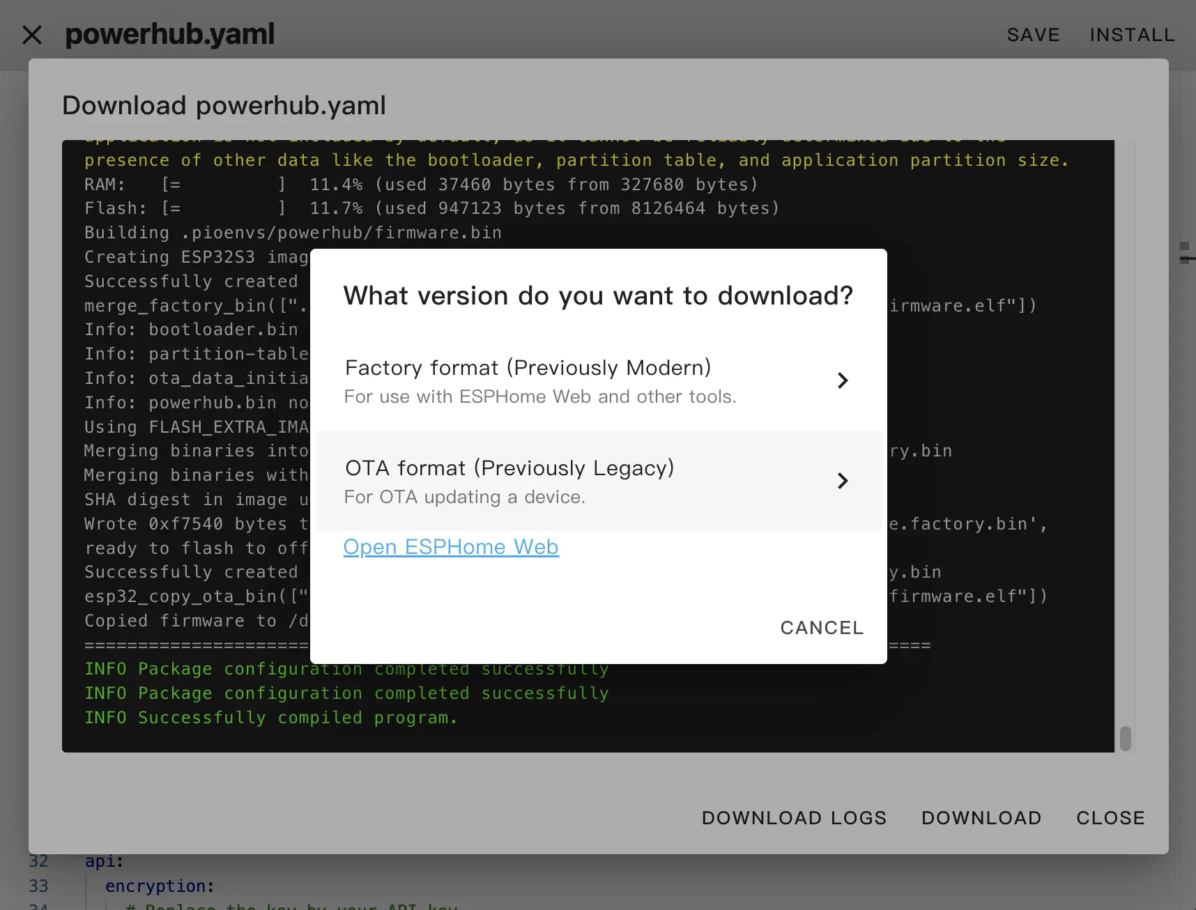
Download and Flash Firmware
Download firmware: Download the Factory Format firmware via the
Manual downloadmethod in ESPHome Builder.Flash firmware using web tools:
Open a browser and visit ESPHome Web to upload the firmware.
Connect PowerHub to the host using a USB-C cable, click
CONNECT, and select the device connection.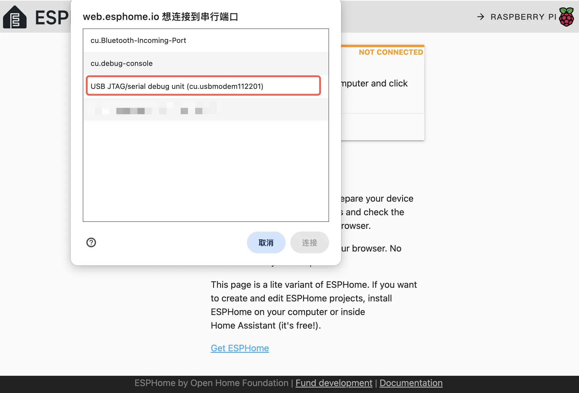
Click
INSTALL, select the previously downloaded firmware to upload, then clickINSTALLagain to flash the firmware to the device.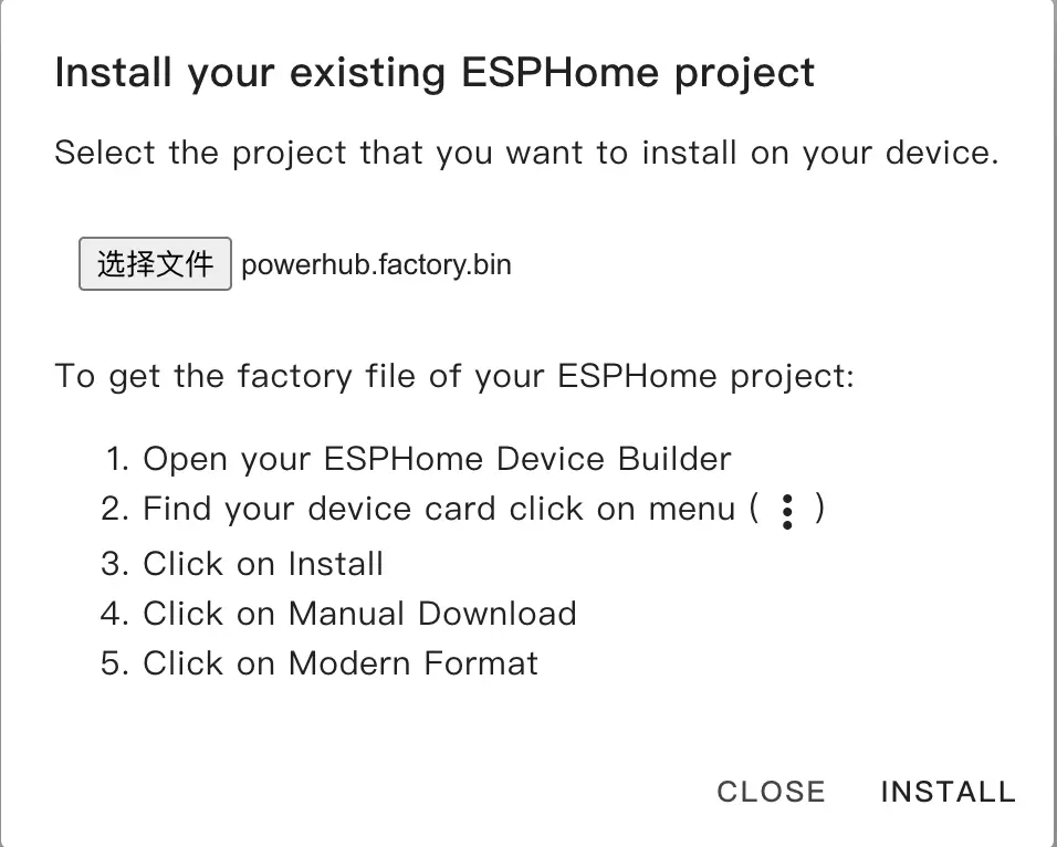
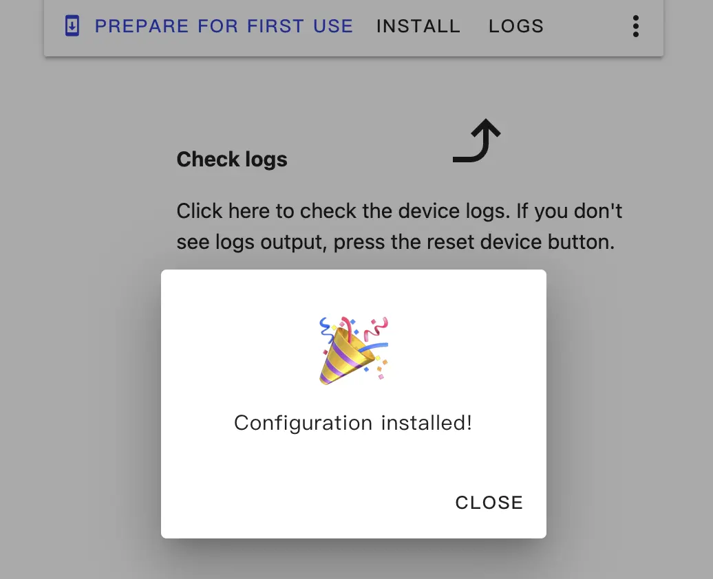
When flashing is complete, the device will automatically reset.
Getting Started
Add Device to Home Assistant Integration
When the device restarts, it will automatically connect to the previously configured network. Under normal circumstances, the device can be discovered in
Settings->Devices & services.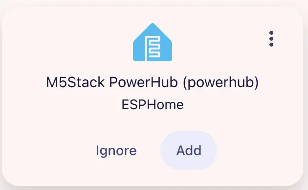
Click
Addto integrate PowerHub into Home Assistant. If an API Encryption Key was previously set, you may need to enter it here for verification.
PowerHub Dashboard Example:
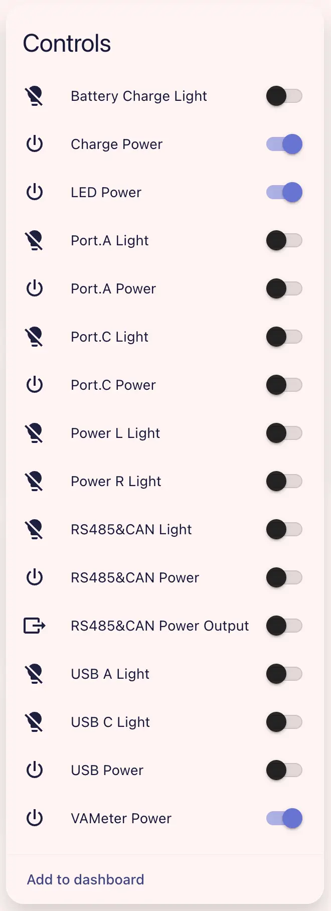
- You can specifically control each light or power output through the light switches and power switches. The drop-down menu sets the USB working mode, output voltage, and current limit for RS485 & CAN interfaces (requires turning on
RS485 & CAN Power Output).
Component/Hub Configuration
I2C is a necessary component for configuring the device.
- This device provides RS485 and CAN interfaces; if you need to use the RS485/CAN interfaces, you need to configure additional components such as Modbus Controller and CAN Bus.
- You can set the USB mode for the USB Type-A or USB Type-C ports; if communication via the USB interface is required, you may need to configure USB Host Interface and TinyUSB.
# Example configuration entry
powerhub:Configuration Variables
- id (Optional, ID): Assign an ID for the PowerHub component.
- update_interval (Optional, Time): The interval to check sensors. Set to
neverto disable updates. Default is10s.
Binary Sensor
The Binary Sensor for powerhub is mainly used to detect if the top PMU button is pressed.
binary_sensor:
  - platform: powerhub
    id: powerhub_binary_sensor
    button:
name: "Top PMU Button"Configuration Variables
- powerhub_id (Optional, ID): The ID of the PowerHub.
- button (Optional): Detects if the top PMU button (rectangular) is pressed. Other options same as Binary Sensor.
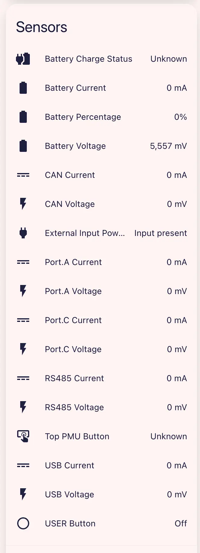
Sensor
The sensors on powerhub report various measured values such as voltage/current.
sensor:
  - platform: powerhub
    battery_voltage:
      name: "Battery Voltage"
      id: bat_volt_sensor
    battery_current:
      name: "Battery Current"
      id: bat_curr_sensor
    battery_level:
      name: "Battery Percentage"
      id: bat_level_sensor
    grove_red_voltage:
      name: "Port.A Voltage"
      id: grove_red_volt_sensor
    grove_red_current:
      name: "Port.A Current"
      id: grove_red_curr_sensor
    grove_blue_voltage:
      name: "Port.C Voltage"
      id: grove_blue_volt_sensor
    grove_blue_current:
      name: "Port.C Current"
      id: grove_blue_curr_sensor
    can_voltage:
      name: "CAN Voltage"
      id: can_volt_sensor
    can_current:
      name: "CAN Current"
      id: can_curr_sensor
    rs485_voltage:
      name: "RS485 Voltage"
      id: rs485_volt_sensor
    rs485_current:
      name: "RS485 Current"
      id: rs485_curr_sensor
    usb_voltage:
      name: "USB Voltage"
      id: usb_volt_sensor
    usb_current:
      name: "USB Current"
id: usb_curr_sensorVAMeter Power switch and the corresponding output channel must be turned on. Readings are only meaningful after the corresponding load is connected.Configuration Variables
- battery_voltage (Optional): Battery voltage. Other options same as Sensor.
- battery_current (Optional): Battery current. Other options same as Sensor.
- battery_level (Optional): Reports battery level as a percentage. Other options same as Sensor.
- grove_red_voltage (Optional): Voltage of the grove red (Port.A) channel. Other options same as Sensor.
- grove_red_current (Optional): Current of the grove red (Port.A) channel. Other options same as Sensor.
- grove_blue_voltage (Optional): Voltage of the grove blue (Port.C) channel. Other options same as Sensor.
- grove_blue_current (Optional): Current of the grove blue (Port.C) channel. Other options same as Sensor.
- can_voltage (Optional): Voltage of the CAN interface. Other options same as Sensor.
- can_current (Optional): Current of the CAN interface. Other options same as Sensor.
- rs485_voltage (Optional): Voltage of the RS485 interface. Other options same as Sensor.
- rs485_current (Optional): Current of the RS485 interface. Other options same as Sensor.
- usb_voltage (Optional): Voltage of the USB interface. Other options same as Sensor.
- usb_current (Optional): Current of the USB interface. Other options same as Sensor.
- powerhub_id (Optional, ID): The ID of the PowerHub.
Text Sensor
The Text Sensor for powerhub reports power status in text format, as well as the internal firmware/bootloader version of the device.
text_sensor:
  - platform: powerhub
    charge_status:
      name: "Battery Charge Status"
      id: bat_charge_status_text_sensor
    vin_status:
      name: "External Input Power Status"
      id: ext_vin_status_text_sensor
    firmware_ver:
      name: "Internal Firmware Version"
      id: int_firm_ver_text_sensor
    bootloader_ver:
      name: "Bootloader Version"
id: boot_ver_text_sensorConfiguration Variables
- charge_status (Optional): Detects if the battery is in a charging state. Other options same as Text Sensor.
- vin_status (Optional): Detects if external input power exists. Other options same as Text Sensor.
- firmware_ver (Optional): Reports the internal firmware version of the device. Other options same as Text Sensor.
- bootloader_ver (Optional): The bootloader version of the device. Other options same as Text Sensor.
- powerhub_id (Optional, ID): The ID of the PowerHub.
Switch
The switches for powerhub allow you to enable or disable individual power channels in the frontend.
switch:
  - platform: powerhub
    led_pwr:
      name: "LED Power"
      id: led_pwr_switch
    usb_pwr:
      name: "USB Power"
      id: usb_pwr_switch
    grove_red_pwr:
      name: "Port.A Power"
      id: grove_red_pwr_switch
    grove_blue_pwr:
      name: "Port.C Power"
      id: grove_blue_pwr_switch
    rs485_can_pwr:
      name: "RS485&CAN Power"
      id: rs485_can_pwr_switch
    vameter_pwr:
      name: "VAMeter Power"
      id: vameter_pwr_switch
    charge_pwr:
      name: "Charge Power"
      id: charge_pwr_switch
    rs485_can_direction:
      name: "RS485&CAN Power Output"
id: rs485_can_direction_switchConfiguration Variables
- led_pwr (Optional): Turn LED power on/off. Default
true. Other options same as Switch. - usb_pwr (Optional): Turn USB power on/off. Other options same as Switch.
- grove_red_pwr (Optional): Turn Port.A (grove red) power on/off. Other options same as Switch.
- grove_blue_pwr (Optional): Turn Port.C (grove blue) power on/off. Other options same as Switch.
- rs485_can_pwr (Optional): Turn RS485 & CAN power on/off. Other options same as Switch.
- vameter_pwr (Optional): Turn VAMeter power on/off. Default
true. Other options same as Switch. - charge_pwr (Optional): Turn charging power on/off. Default
true. Other options same as Switch. - rs485_can_direction (Optional): Controls the output direction of RS485 & CAN power; turning it on enables output. Other options same as Switch.
- powerhub_id (Optional, ID): The ID of the PowerHub.
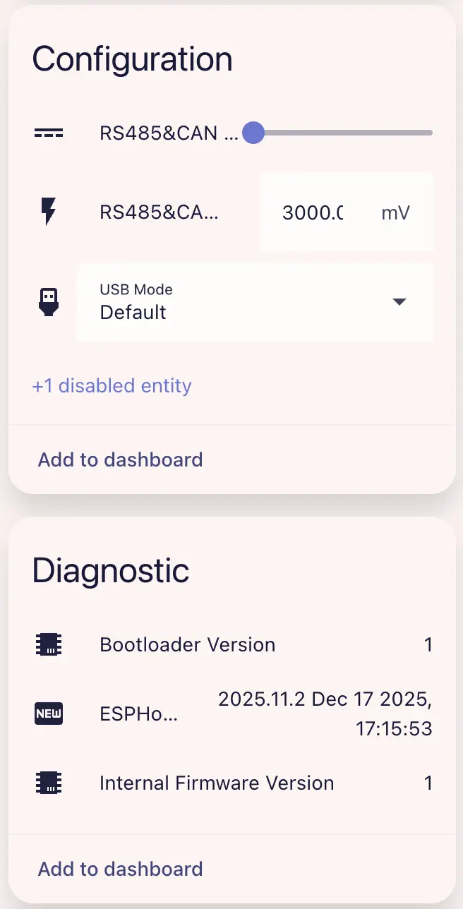
Select
The select for powerhub can be used to switch the USB mode of the USB Type-A or USB Type-C interface.
select:
  - platform: powerhub
    usb_mode:
      name: "USB Mode"
id: usb_mode_selectConfiguration Variables
- usb_mode (Optional): Sets the host/device mode for USB Type-A or USB Type-C ports. Please note that both ports cannot be set to USB host mode at the same time.
Default is device mode. Optional values are
Default,Host for USB-C, orHost for USB-A. Other options same as Select. - powerhub_id (Optional, ID): The ID of the PowerHub.
Number
The output voltage and current limits for the RS485 & CAN interface can be set via number.
number:
  - platform: powerhub
    rs485_can_output_voltage:
      name: "RS485&CAN Output Voltage"
    rs485_can_current_limit:
name: "RS485&CAN Output Current Limit"Configuration Variables
- rs485_can_output_voltage (Optional): Sets the output voltage of the RS485 & CAN interface. Default
3000mV. Only takes effect when the switchrs485_can_directionis turned on. Other options same as Number. - rs485_can_current_limit (Optional): Sets the output current limit for the RS485 & CAN interface. Default
13mA. Only takes effect when the switchrs485_can_directionis turned on. Other options same as Number. - powerhub_id (Optional, ID): The ID of the PowerHub.
Light
Each power channel of powerhub comes with a status RGB LED to indicate power status.
light:
  - platform: powerhub
    usb_c_rgb:
      name: "USB C Light"
    usb_a_rgb:
      name: "USB A Light"
    grove_blue_rgb:
      name: "Port.C Light"
    grove_red_rgb:
      name: "Port.A Light"
    rs485_can_rgb:
      name: "RS485&CAN Light"
    bat_charge_rgb:
      name: "Battery Charge Light"
    pwr_l_rgb:
      name: "Power L Light"
    pwr_r_rgb:
name: "Power R Light"Configuration Variables
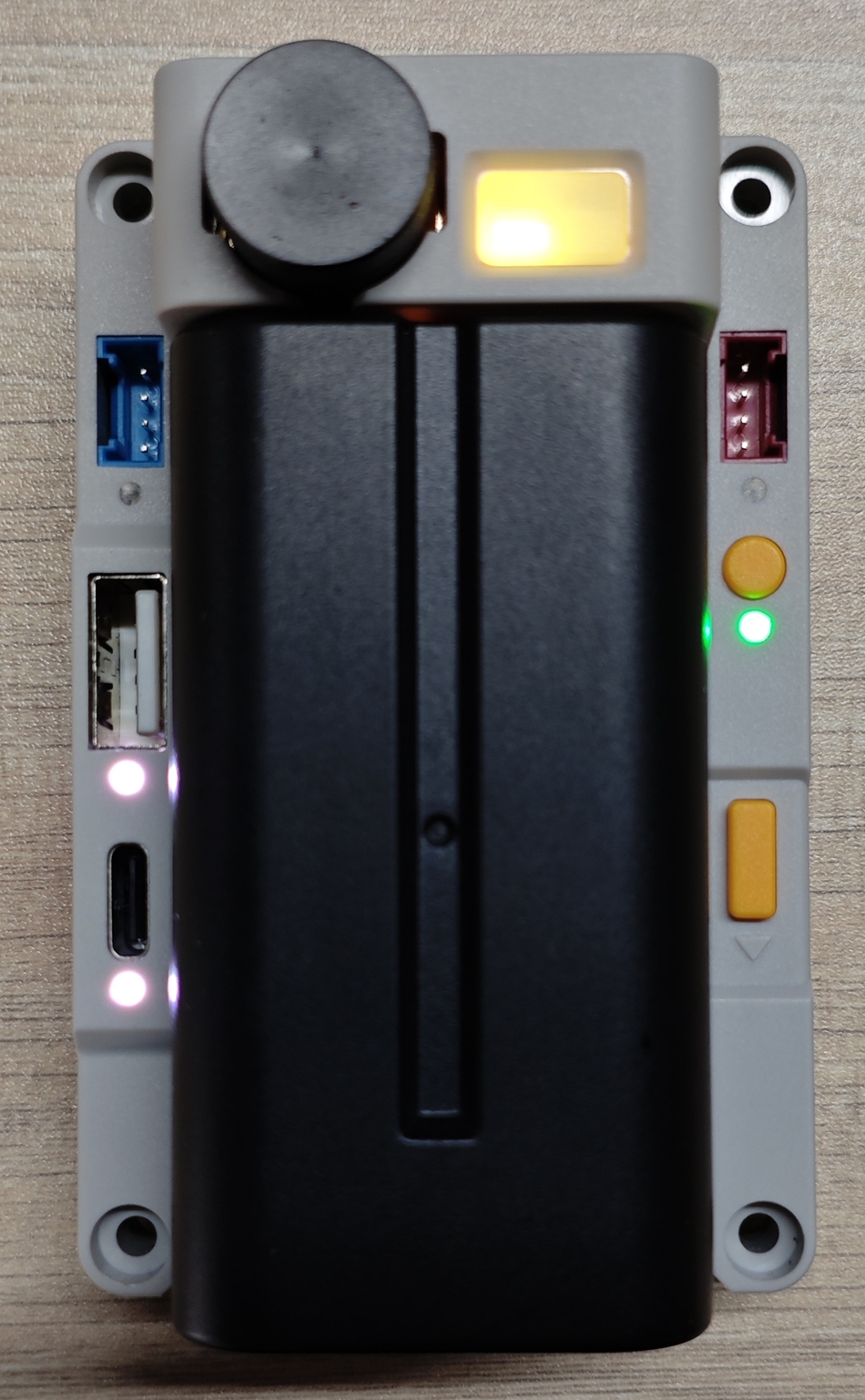
- usb_c_rgb (Optional): Controls the RGB LED below the USB Type-C interface. Other options same as Light.
- usb_a_rgb (Optional): Controls the RGB LED below the USB Type-A interface. Other options same as Light.
- grove_blue_rgb (Optional): Controls the RGB LED below the Port.C (grove blue) interface. Other options same as Light.
- grove_red_rgb (Optional): Controls the RGB LED below the Port.A (grove red) interface. Other options same as Light.
- rs485_can_rgb (Optional): Controls the RGB LED below the RS485 & CAN interface. Other options same as Light.
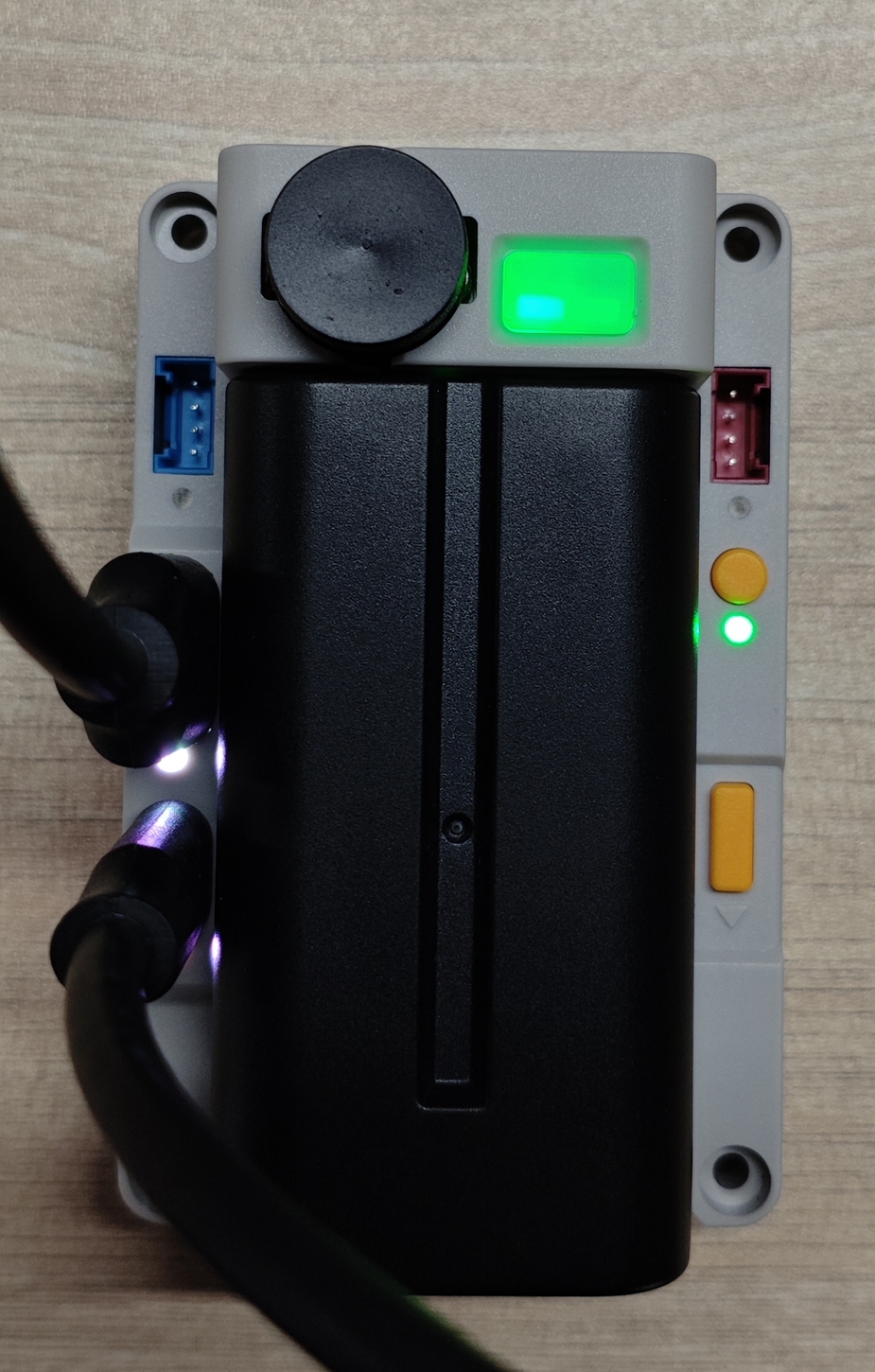
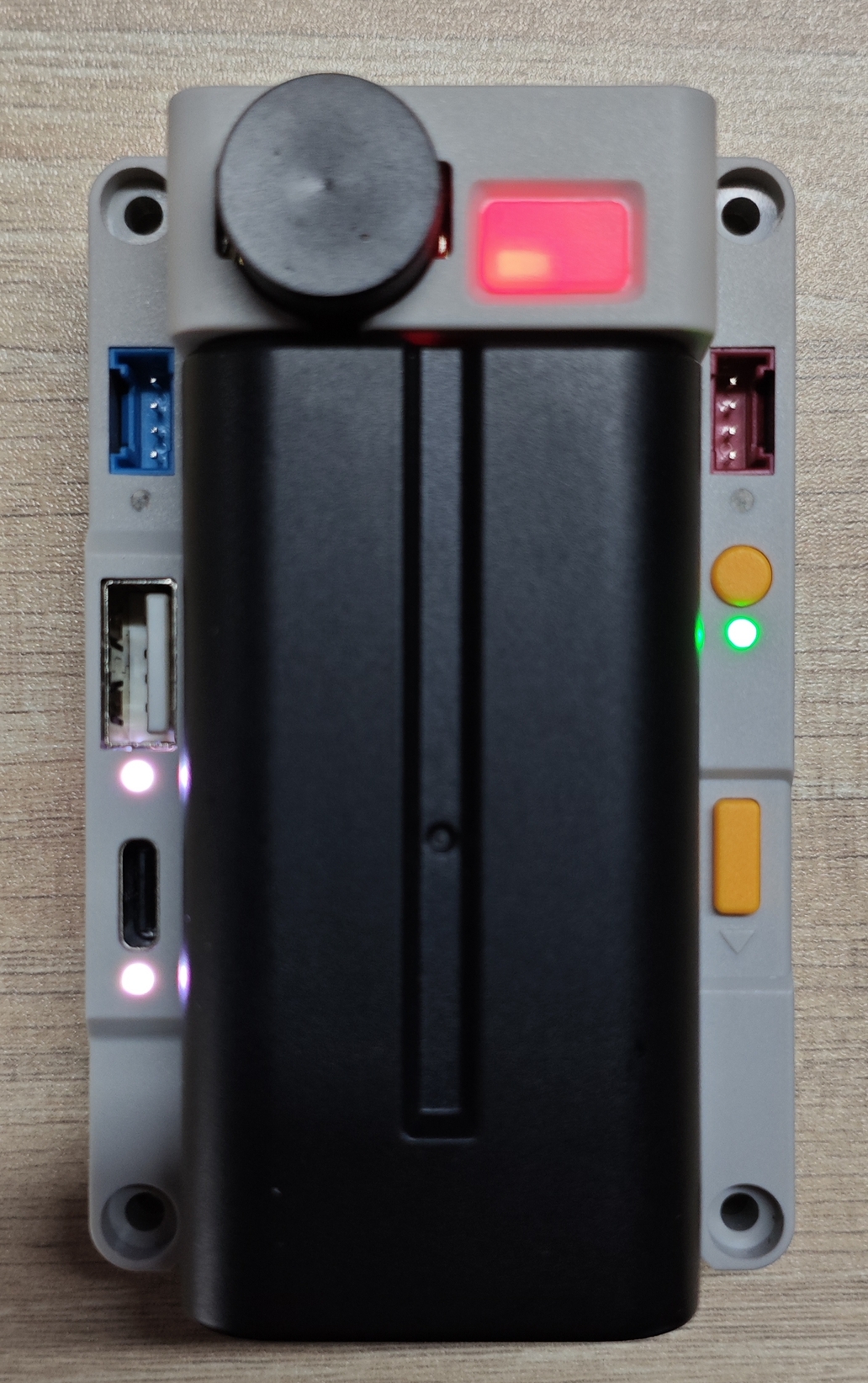
- bat_charge_rgb (Optional): Controls the RGB LED for battery charging status. This LED is located below the yellow circular button. Other options same as Light.
- pwr_l_rgb (Optional): Controls the left power indicator RGB LED. This LED is located inside the left half of the top PMU button (rectangular). Other options same as Light.
- pwr_r_rgb (Optional): Controls the right power indicator RGB LED. This LED is located inside the right half of the top PMU button (rectangular). Other options same as Light.
- powerhub_id (Optional, ID): The ID of the PowerHub.
Lights can be used very conveniently to indicate channel status. You can selectively update the lights based on various Sensor data, such as turning on the lights in the PMU button at startup:
esphome:
  ...
  on_boot:
    then:
      # Turn on the power (L/R) light
      - light.turn_on:
          id: led_pwr_l
          brightness: 100%

      - light.turn_on:
          id: led_pwr_r
brightness: 100%Selectively update the top PMU button lights based on battery level readings:
sensor:
  - platform: powerhub
    ...
    battery_level:
      name: "Battery Percentage"
      id: bat_level_sensor
      on_value:
        - lambda: |-
            auto call_1 = id(led_pwr_l).turn_on();
            auto call_2 = id(led_pwr_r).turn_on();
            auto call_off_1 = id(led_pwr_l).turn_off();
            auto call_off_2 = id(led_pwr_r).turn_off();
            call_1.set_transition_length(1000);
            call_2.set_transition_length(1000);
            call_off_1.set_transition_length(1000);
            call_off_2.set_transition_length(1000);
            call_1.set_color_mode(ColorMode::RGB);
            call_2.set_color_mode(ColorMode::RGB);
            // if read battery level is unknown
            // set the LED color to white
            if ( std::isnan(x) ) {
              call_1.set_rgb(1.0, 1.0, 1.0);
              call_2.set_rgb(1.0, 1.0, 1.0);
              call_1.set_brightness(1.0);
              call_2.set_brightness(1.0);
              call_1.perform();
              call_2.perform();
              return;
            }

            if ( x > 80.0f && x <= 100.0f ) {
                call_1.set_rgb(0, 1.0, 0);
                call_2.set_rgb(0, 1.0, 0);
                call_1.set_brightness(1.0);
                call_2.set_brightness(1.0);
                call_1.perform();
                call_2.perform();
            } else if ( x > 50.0f && x <= 80.0f ) {
                call_1.set_rgb(0, 1.0, 0);
                call_2.set_rgb(0, 1.0, 0);
                call_1.set_brightness(1.0);
                call_2.set_brightness(0.8);
                call_1.perform();
                call_2.perform();
            } else if ( x > 20.0f && x <= 50.0f ) {
                call_1.set_rgb(1.0, 0.95, 0.19); // left only one LED on with YELLOW color suggest low power
                call_1.perform();
                call_off_2.perform();
            } else if ( x > 5.0f && x <= 20.0f ){
                call_1.set_rgb(1.0, 0.43, 0.32); // left only one LED on with RED color suggest extremely low power
                call_1.perform();
                call_off_2.perform();
            } else {
                call_1.set_rgb(1.0, 0.43, 0.32);
                call_1.set_brightness(0.8); // almost empty
                call_1.perform();
                call_off_2.perform();
            }
...Alternatively, turn on/off the corresponding LED indicator light when turning on/off a channel switch:
switch:
  - platform: powerhub
    ...
    usb_pwr:
      name: "USB Power"
      id: usb_pwr_switch
      on_turn_on:
        - light.turn_on:
            id: led_usb_a
            brightness: 90%
            # Color maybe
            # red: 100%
            # green: 100%
            # blue: 100%
        - light.turn_on:
            id: led_usb_c
            brightness: 90%
      on_turn_off:
        - light.turn_off:
            id: led_usb_a
        - light.turn_off:
            id: led_usb_c

    grove_red_pwr:
      name: "Port.A Power"
      id: grove_red_pwr_switch
      on_turn_on:
        - light.turn_on:
            id: led_grove_red
            brightness: 90%
      on_turn_off:
        - light.turn_off:
            id: led_grove_red

    grove_blue_pwr:
      name: "Port.C Power"
      id: grove_blue_pwr_switch
      on_turn_on:
        - light.turn_on:
            id: led_grove_blue
            brightness: 90%
      on_turn_off:
        - light.turn_off:
            id: led_grove_blue

    rs485_can_pwr:
      name: "RS485&CAN Power"
      id: rs485_can_pwr_switch
      on_turn_on:
        - light.turn_on:
            id: led_rs485_can
            brightness: 90%
      on_turn_off:
        - light.turn_off:
            id: led_rs485_can

    charge_pwr:
      name: "Charge Power"
      id: charge_pwr_switch
      restore_mode: RESTORE_DEFAULT_ON
      on_turn_on:
        - light.turn_on:
            id: led_bat_charge
            brightness: 90%
      on_turn_off:
        - light.turn_off:
            id: led_bat_charge
...Using pulse/breath light to indicate charging status when battery is charging (requires adding pulse effect to the light):
light:
  - platform: powerhub
    ...
    bat_charge_rgb:
      id: led_bat_charge
      name: "Battery Charge Light"
      effects:
        - pulse:
            name: "Slow Pulse"
            transition_length: 500ms
            update_interval: 2s
...text_sensor:
- platform: powerhub
charge_status:
name: "Battery Charge Status"
id: bat_charge_status_text_sensor
on_value:
- lambda: |-
static std::string last_state = "";
if (last_state == x) return;
last_state = x;
auto call = id(led_bat_charge).turn_on();
call.set_brightness(0.9);
call.set_color_mode(ColorMode::RGB);
if (x == "Charging") {
// Pulse green
call.set_rgb(0, 1.0, 0);
call.set_effect("Slow Pulse");
} else if (x == "Discharging") {
// Solid green
call.set_rgb(0, 1.0, 0);
call.set_effect("None");
} else {
// Solid white
call.set_rgb(1.0, 1.0, 1.0);
call.set_effect("None");
}
call.perform();Time
powerhub has a built-in RX8130 RTC chip, which can serve as the time source for the device.
time:
  - platform: powerhub
id: powerhub_timeConfiguration Variables
- powerhub_id (Optional, ID): The ID of the PowerHub.
- Other options same as Base Time Configuration.
powerhub.write_time Action
This Action triggers syncing the current system time to the RTC hardware.
on_...:
  - powerhub.write_time

  # If powerhub id needs to be specified
  - powerhub.write_time:
id: powerhub_timepowerhub.read_time Action
This Action triggers syncing the current system time from the RTC hardware.
update_interval) This action can be used to trigger an additional sync.
on_...:
  - powerhub.read_time

  # If powerhub id needs to be specified
  - powerhub.read_time:
id: powerhub_timeConfiguration Example
In general, at least one additional time source is required for synchronization with the RTC. Such external time sources may not always be available (e.g., restricted network). To ensure that the system time is valid and reliable, the system should read the RTC once at startup and then attempt to sync with a reliable external time source. After a successful sync with another time source, that time can then be written back to the RTC to resync it.
esphome:
  on_boot:
    then:
      # Read RTC time once at system startup
      powerhub.read_time:

time:
  - platform: powerhub
    # If the external RTC is not more accurate than the internal clock, repeated sync is not needed
    timezone: Asia/Shanghai
    update_interval: never

  - platform: homeassistant
    # Change to repeat sync attempts via network ...
    on_time_sync:
      then:
        # ... update RTC after successful sync
        powerhub.write_time: