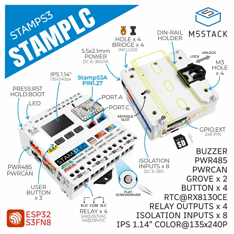
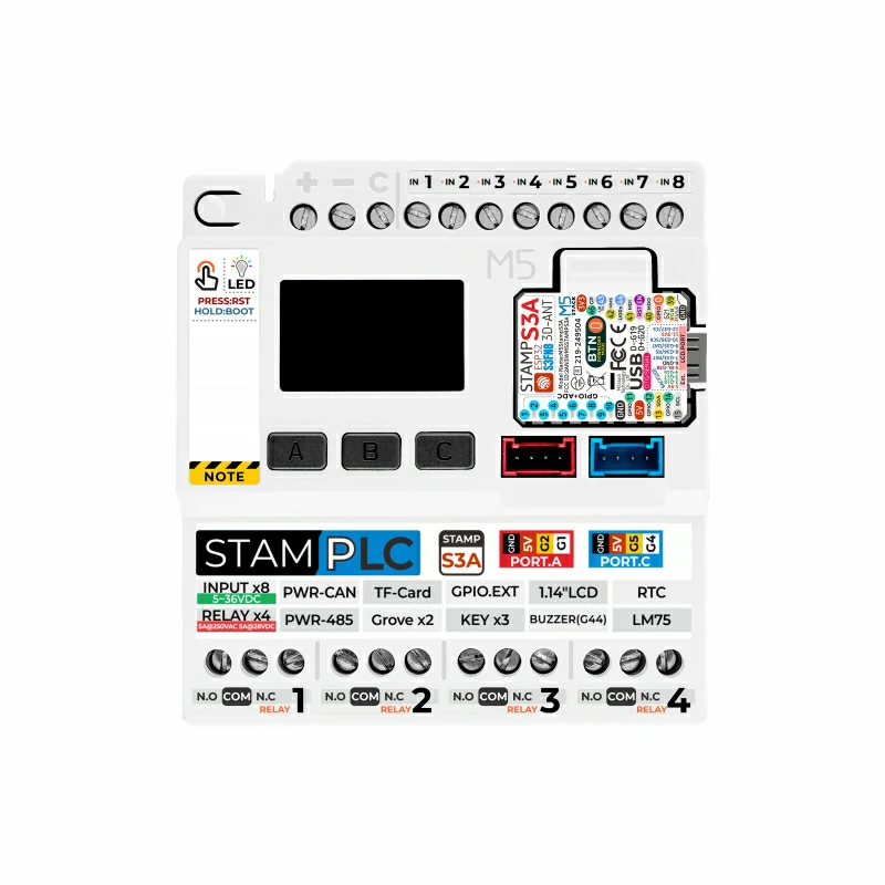
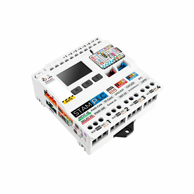
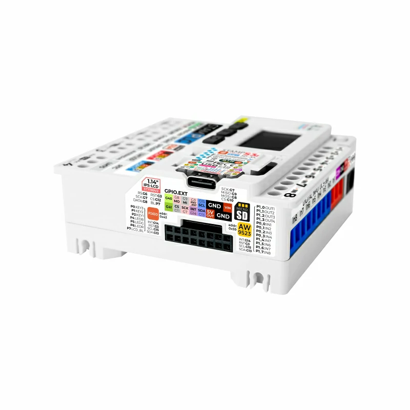
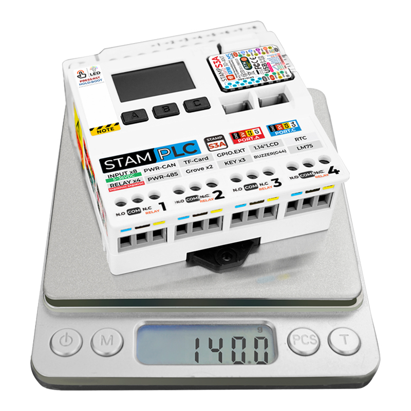
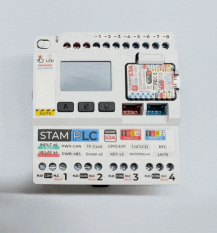
StamPLC is an IoT Programmable Logic Controller designed for industrial automation and remote monitoring. The product uses the Stamp-S3A control module, offering strong processing power and efficient wireless connectivity. In terms of control, StamPLC provides 8-channel optocoupler isolated digital inputs and 4-channel relay outputs (supporting AC / DC loads), along with GPIO.EXT and 2 HY2.0-4P ports, making the connection of various sensors and actuators simple and reliable. With onboard PWR-CAN and PWR-485 interfaces, the device can be seamlessly integrated into industrial field bus networks to achieve remote data transmission and centralized control. For human-machine interaction, the product features a 1.14-inch color display, RESET/BOOT keys, 3 user buttons, and a buzzer, enabling users to configure parameters and monitor status in real-time, and promptly alert in case of anomalies. To suit harsh industrial environments, StamPLC supports DC 6 ~ 36V wide-voltage power supply and is designed for DIN rail installation to ensure sturdy mounting; the built-in microSD slot facilitates data storage and firmware upgrading. Its environmental monitoring system integrates the LM75 temperature sensor and INA226 voltage/current sensor to provide real-time feedback on operating status, while the RTC (RX8130CE) module ensures accurate time synchronization and log recording. The factory firmware by default uploads data to M5's EZData cloud platform, automatically generating monitoring pages, offering users a convenient remote cloud access and control method. This product is suitable for industrial automation, remote monitoring, and smart manufacturing applications.
This demo will introduce how to add the device into Home Assistant
Note
Power Notes
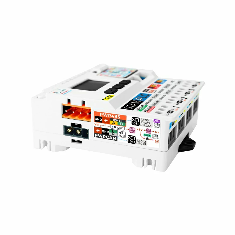
The PWR-CAN and PWR-485 output power pins of StamPLC are directly connected to the main input power, so please ensure that the input voltage matches the power requirements of the external expansion device during use. For example, when using StamPLC to control Unit Roller485 or Unit RollerCAN, it is recommended to keep the input voltage between DC 6 ~ 16V to prevent damage caused by voltage mismatch.
Features
Stamp-S3A control module (ESP32-S3FN8)
EZData cloud monitoring
8-channel optocoupler isolated digital input
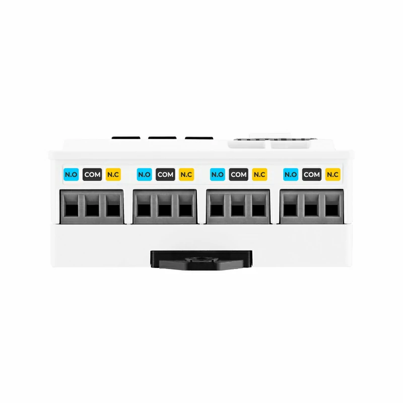
4-channel relay output (AC / DC)
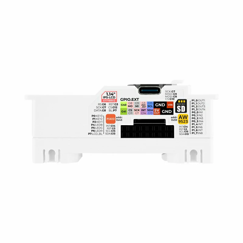
1.14-inch color screen (ST7789v2)
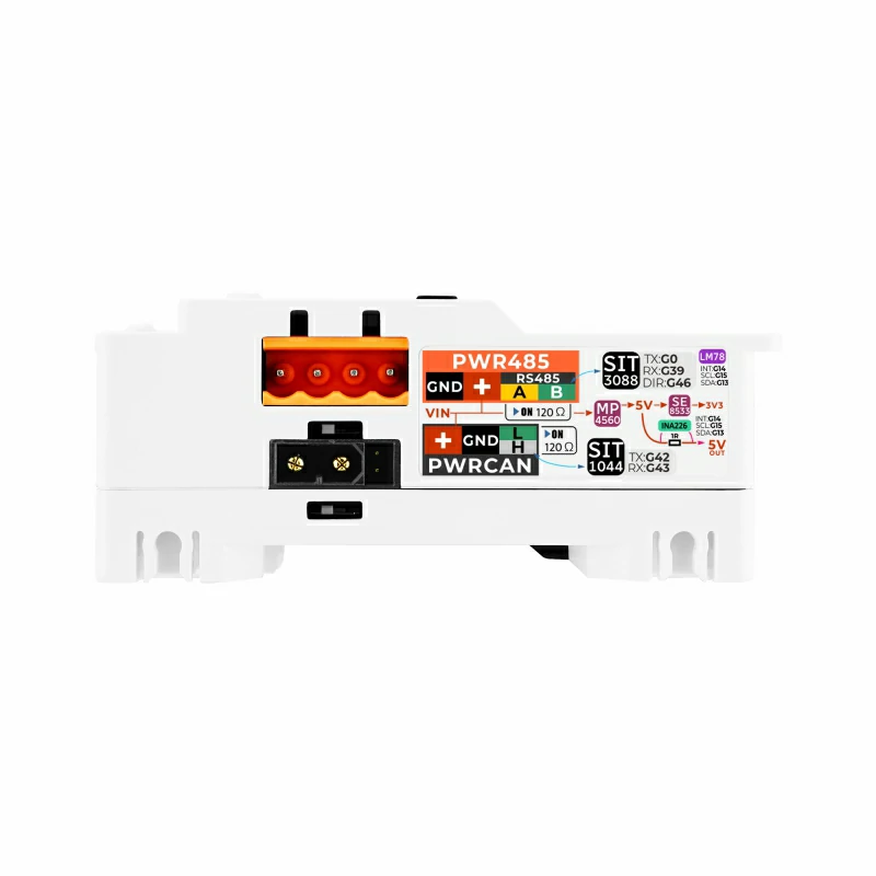
PWR-CAN & PWR-485 interface
Wide voltage input (DC 6 ~ 36V)
Integrated INA226 voltage / current sensor, capable of measuring the voltage and current of the VIN input on the DC power interface and the EXT expansion interface
Internal temperature sensor
User buttons
microSD slot
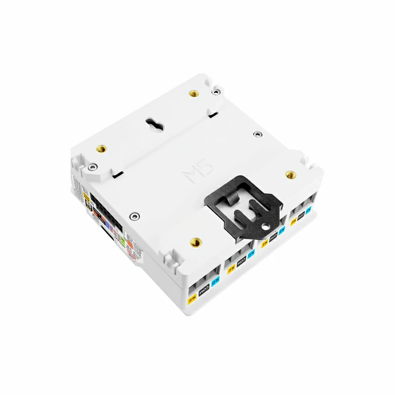
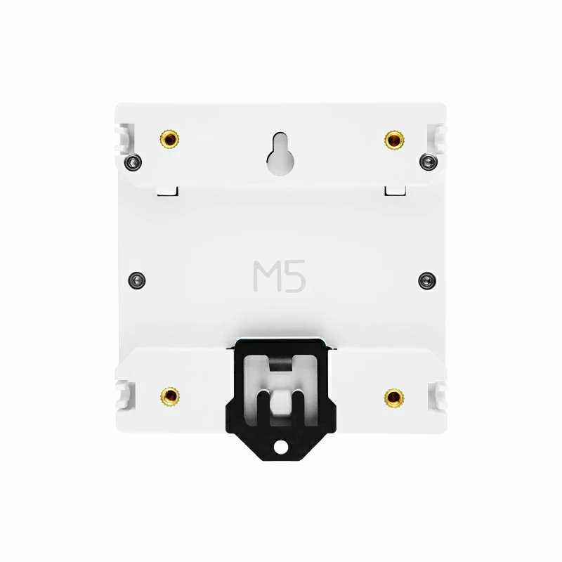
DIN rail installation
Buzzer
HY2.0-4P port
RTC module
Development Platform
UiFlow2
Arduino IDE
ESP-IDF
PlatformIO
Includes
1 x StamPLC
4 x Mounting accessories
4 x Screw clamp mounting parts
Applications
Industrial automation and remote control
Distributed control systems
Smart manufacturing
Specifications
Specification
Parameter
Module Model
Stamp-S3A Control Module
SoC
ESP32-S3FN8@Xtensa LX7 dual-core, main frequency up to 240MHz
Flash
8MB
Wi-Fi
2.4 GHz Wi-Fi
Digital Input
8-channel optocoupler isolated digital input, input voltage range: DC 5 ~ 36V
Digital Output
4-channel relay output
Relay
AC 5A@250V DC 5A@28V
DC Power Supply
Supports DC 6 ~ 36V @ 1A wide-voltage supply DC power interface: DC5521 female 5.5 x 2.1mm (inner positive outer negative)
Expansion Port
GPIO.EXT port, 2 HY2.0-4P ports
Communication Port
Onboard PWR-CAN and PWR-485 interfaces
PWR-CAN Port
XT30 (2+2) PW-M
PWR-485 Port
HT3.96-4P
Display
1.14-inch color display (135×240 resolution), driver chip ST7789v2
Interaction
1 RESET/BOOT button, 3 user buttons, buzzer
Data Storage
Built-in microSD slot
Sensor
LM75 temperature sensor, INA226 voltage/current sensor, RTC (RX8130CE)
IO Capacity
2x8 expansion port max output: DC 4.76V@700mA HY2.0-4P port load capacity test: DC 4.81V@700mA
Power Consumption
Standby current: (5V supply) DC 5V@21.60mA, (12V supply) DC 12V@15.22mA Working current: (5V supply) DC 5V@93.89mA, (12V supply) DC 12V@47.84mA
Installation
DIN rail installation
Operating Temp
0 ~ 40°C
Product Size
72.0 x 80.0 x 33.4mm
Product Weight
138.9g
Package Size
102.0 x 94.0 x 33.4mm
Gross Weight
177.5g
Learn
Download Mode
Download Mode
To enter download mode, after connecting the data cable, hold down the Boot button until the red indicator light turns on, then release the Boot button to enter download mode.
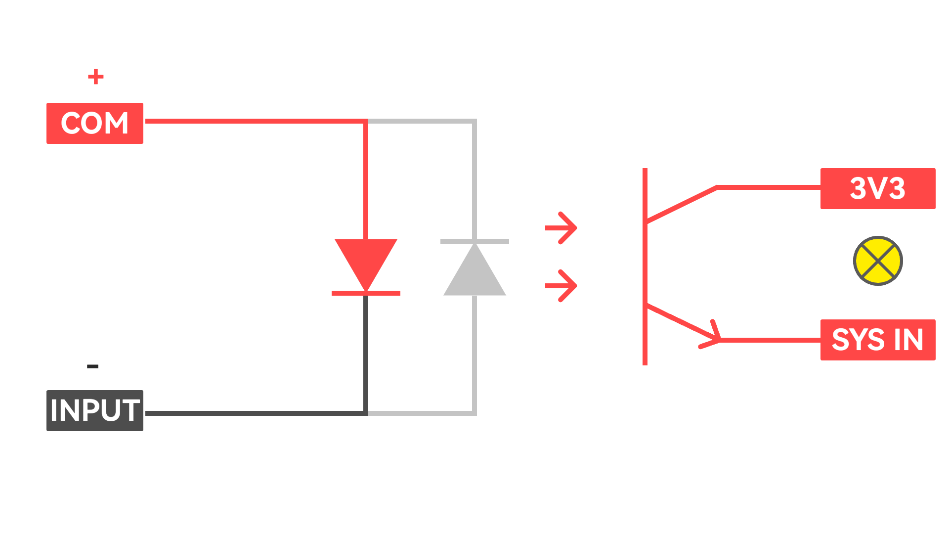
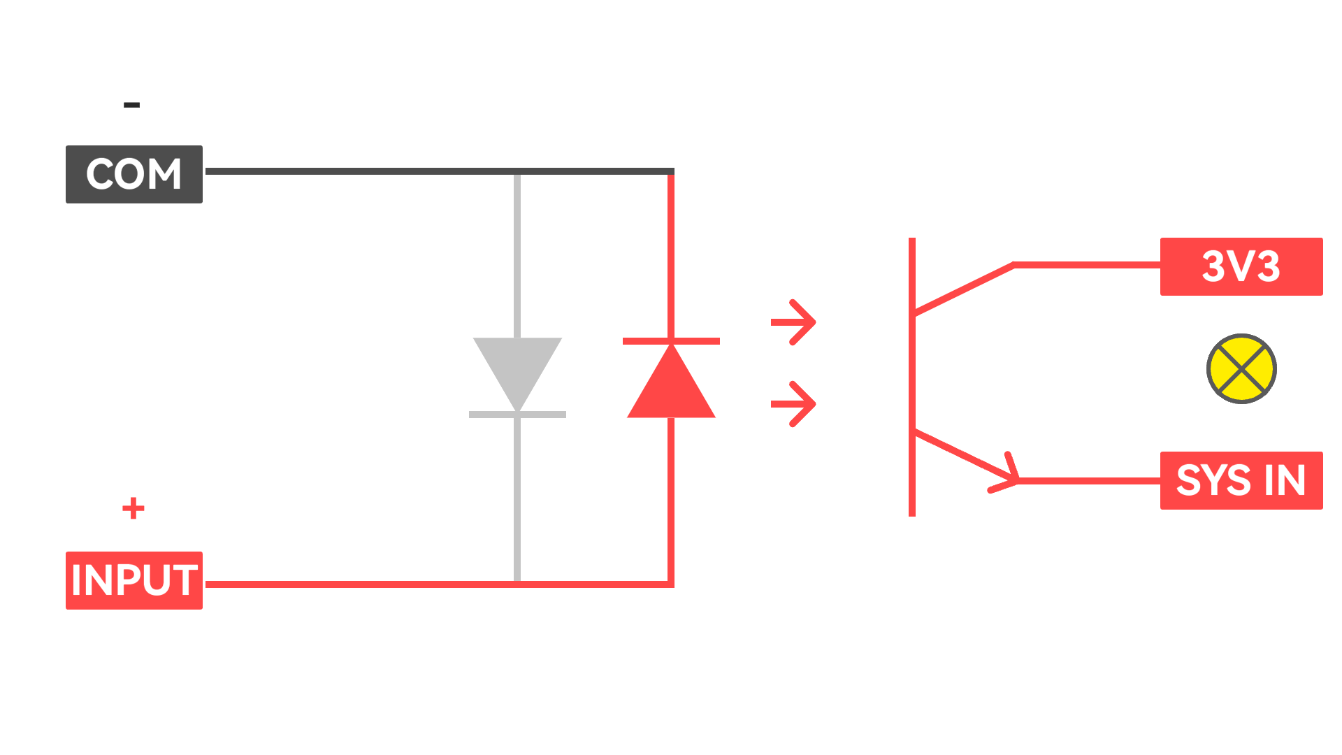
Signal Input Sensor Wiring Method
The input channel integrates optocoupler isolation, supporting DC 5 ~ 36V high/low level signal input acquisition to adapt to different sensor input types.
Low-level signal input wiring: - COM connects to the positive terminal of sensor power supply - INPUT connects to sensor input signal
High-level signal input wiring: - COM connects to negative terminal of sensor power supply - INPUT connects to sensor input signal
The RGB LED only supports color generation through on/off combinations of the three independent R/G/B channels, and does not support PWM dimming for brightness control or gradient effects.
By default, StamPLC firmware initializes the Modbus slave after startup. External devices can control the StamPLC via the PWR-485 interface using Modbus RTU protocol, with the following register mapping.
Register Map:
Coils (Read/Write)
Address 0: Relay 1 output (true/false)
Address 1: Relay 2 output (true/false)
Address 2: Relay 3 output (true/false)
Address 3: Relay 4 output (true/false)
Input Registers (Read-only)
Address 0-7: Inputs (true/false) - 8 registers
Address 8-9: Temperature (FLOAT32) - 2 registers
Address 10-11: Bus Voltage (FLOAT32) - 2 registers
Address 12-13: Shunt Current (FLOAT32) - 2 registers