Home Assistant
Media Player
Expansion
Sensor
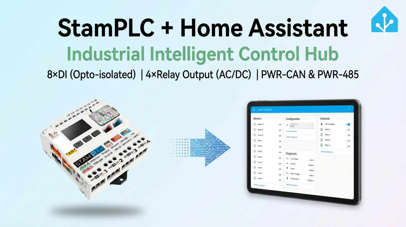
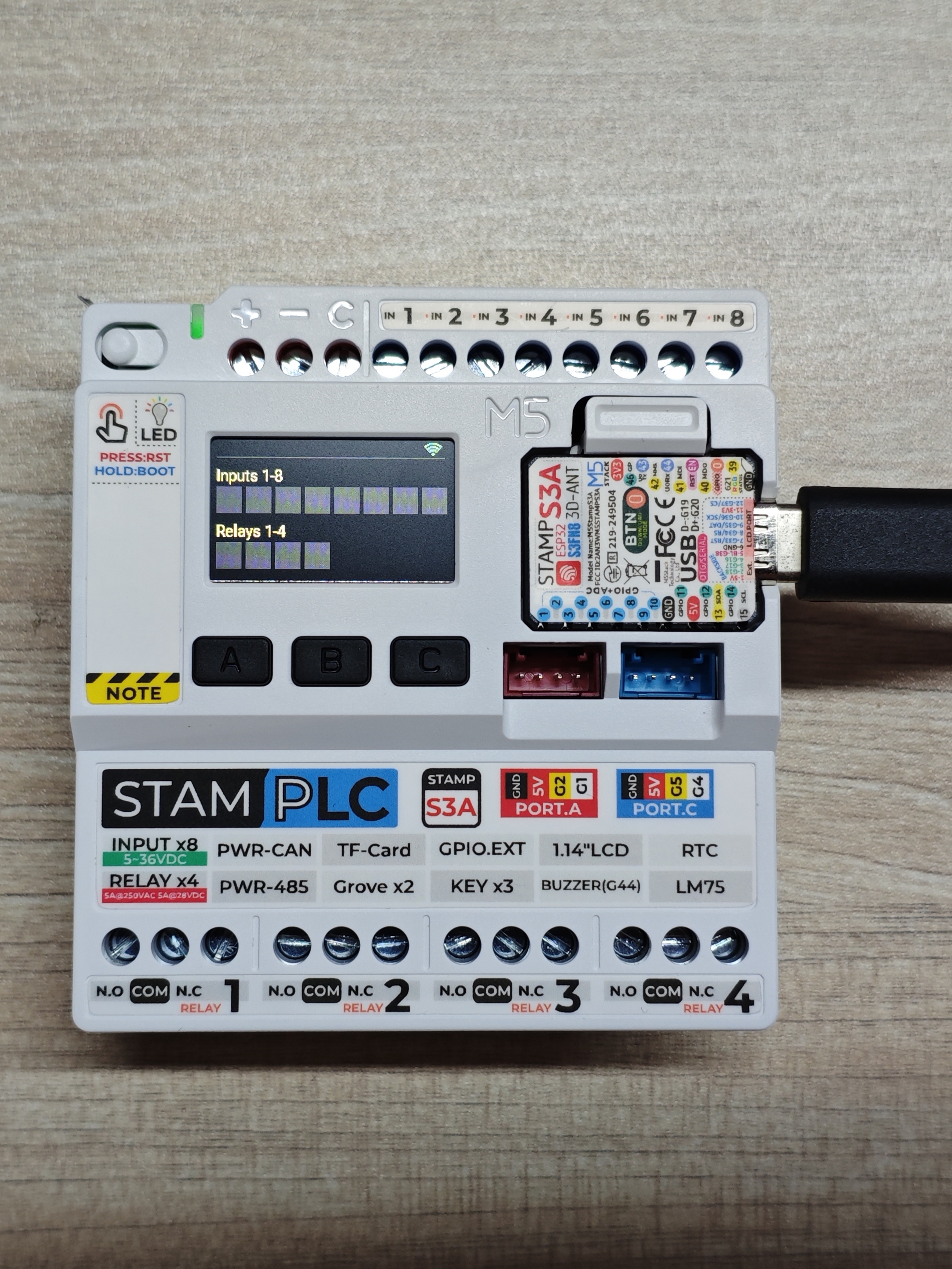
StamPLC Home Assistant Integration
This chapter describes how to integrate the IoT programmable logic controller StamPLC into Home Assistant.
Preparation
- Home Assistant Host.
- Install and enable ESPHome Builder in Home Assistant.
Quick Start
Click the button below to flash the firmware with one click. Follow the on-screen instructions to complete the configuration and quickly experience StamPLC integrated with Home Assistant. For one-click flashing and subsequent configuration, please refer to the tutorial.
Note
- In this tutorial, the kit was compiled and uploaded under ESPHome 2025.10.3. If you encounter compilation/upload issues, consider switching ESPHome to this version.
Create Device
Open ESPHome Builder in Home Assistant and create an empty configuration file.
Click the
NEW DEVICEbutton in the bottom right corner.Click
CONTINUEin the pop-up box.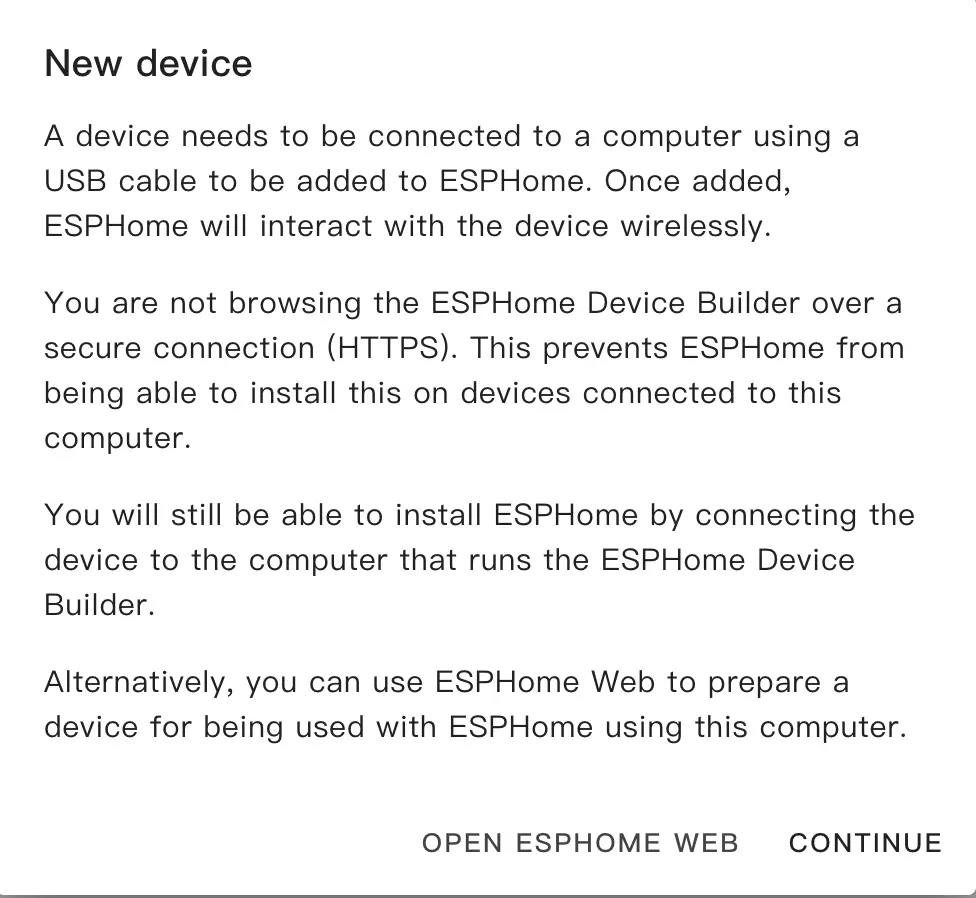
Select
Empty Configuration.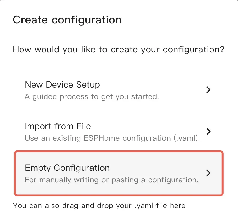
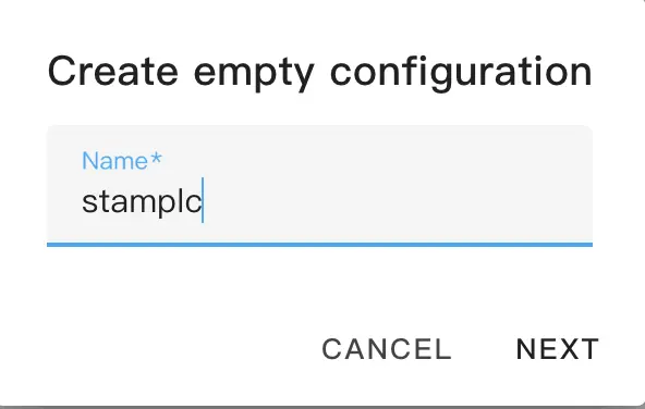
Name the file (Optional).
Click
EDITon the newly generated configuration file.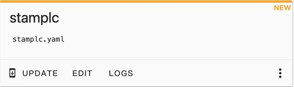
Copy the contents of configurations.yaml into the configuration file.
Change network configuration or API information as needed, such as creating an API Encryption Key for authentication:
api:
  encryption:
key: "Your_Encryption_Key"Or change the timezone settings:
timezone: Europe/LondonChange to the appropriate timezone:
timezone: Asia/ShanghaiClick
SAVEandINSTALLin the top right corner in sequence, then selectManual download.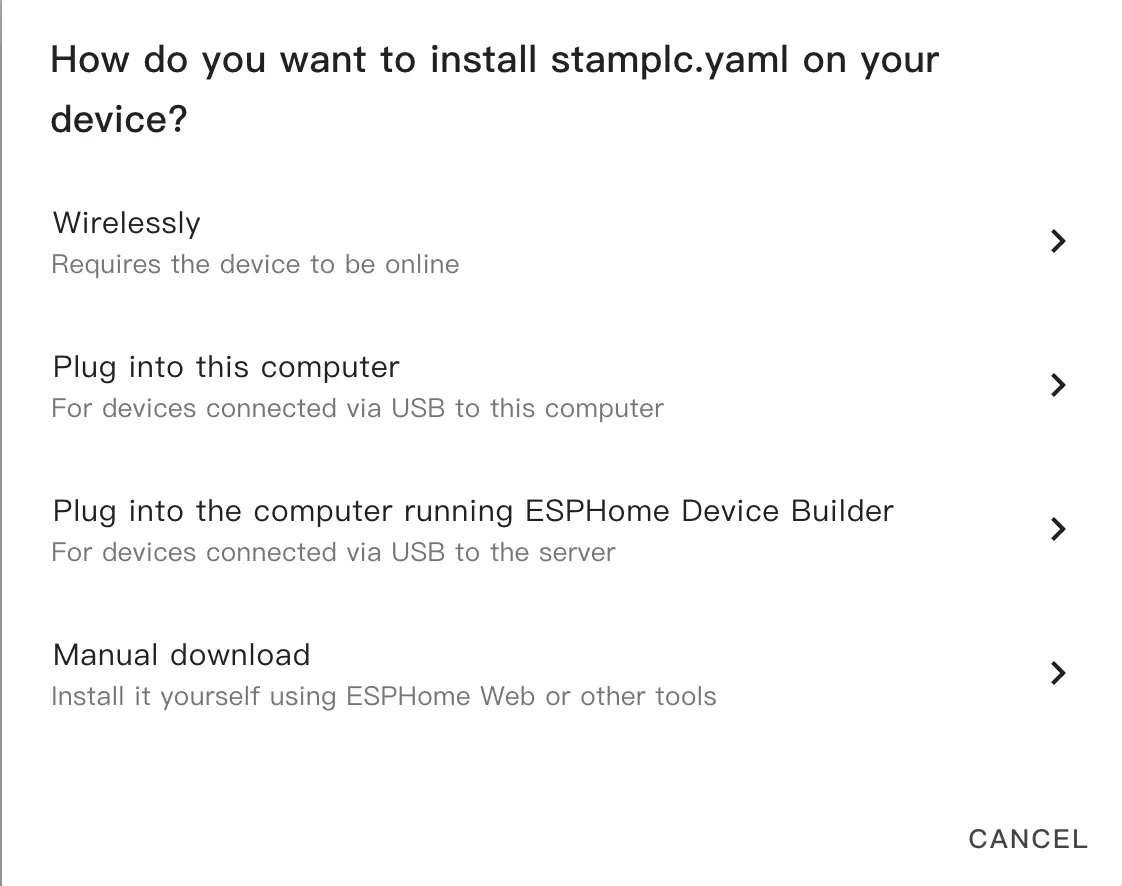
The code will be generated and the project will be compiled.
When compilation is complete, select
Factory formatto download the firmware.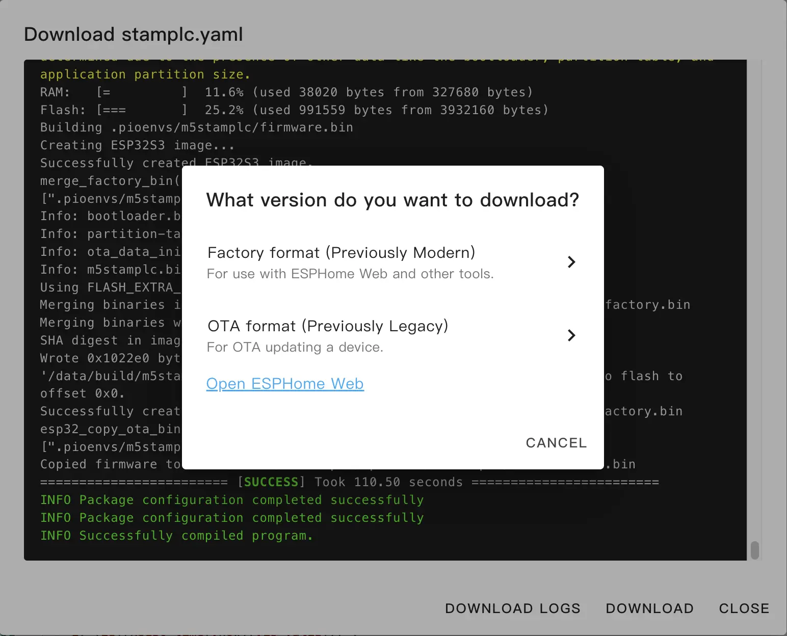
Download and Flash Firmware
Download firmware: Download the Factory Format firmware via the
Manual downloadmethod in ESPHome Builder.Flash firmware using web tools:
Open a browser and visit ESPHome Web to upload the firmware.
Connect StamPLC to the host using a USB-C cable, click
CONNECT, and select the device connection.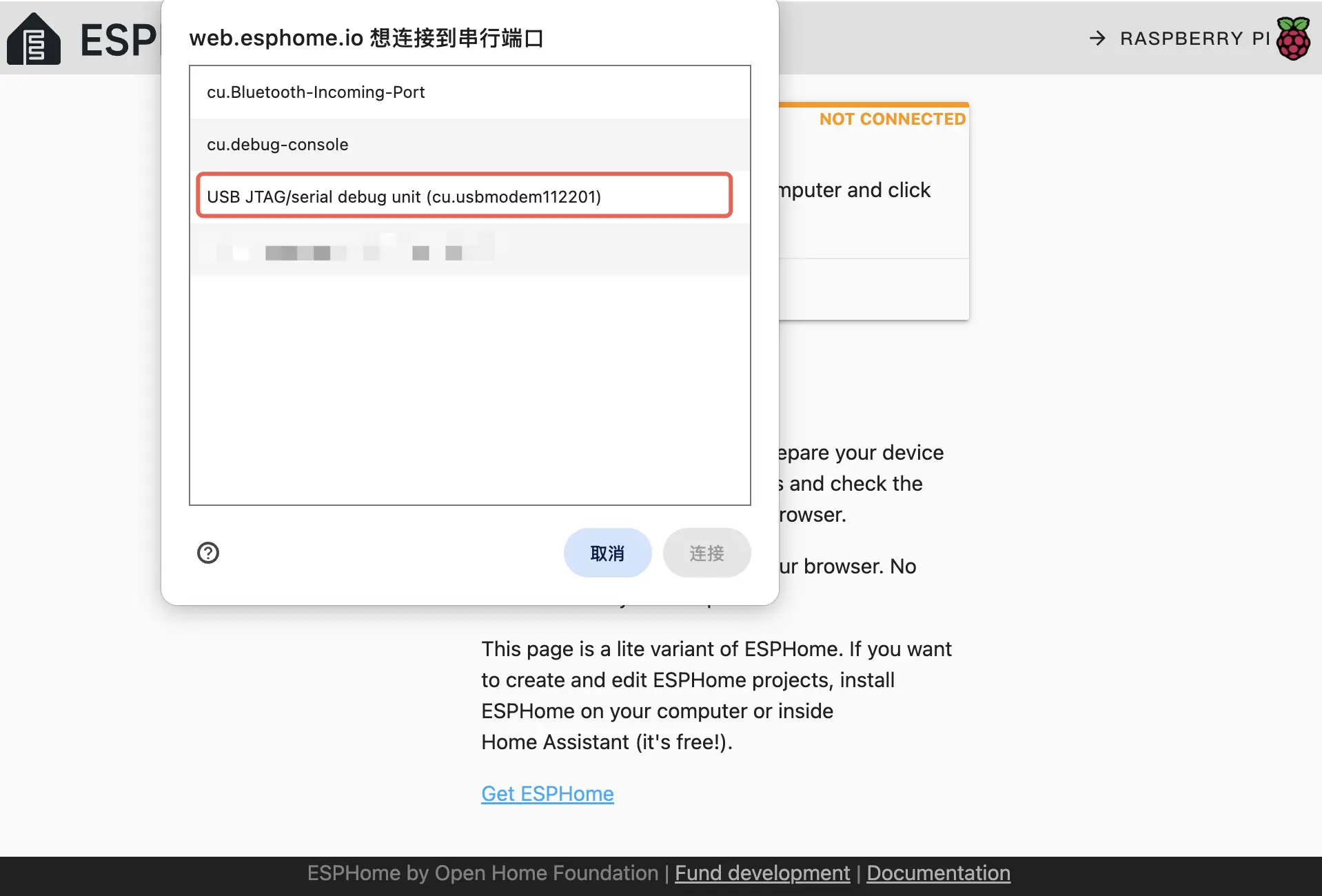
Click
INSTALL, select the previously downloaded firmware to upload, then clickINSTALLagain to flash the firmware to the device.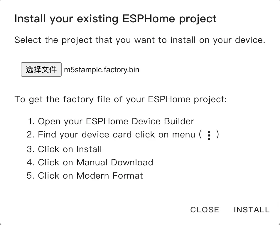
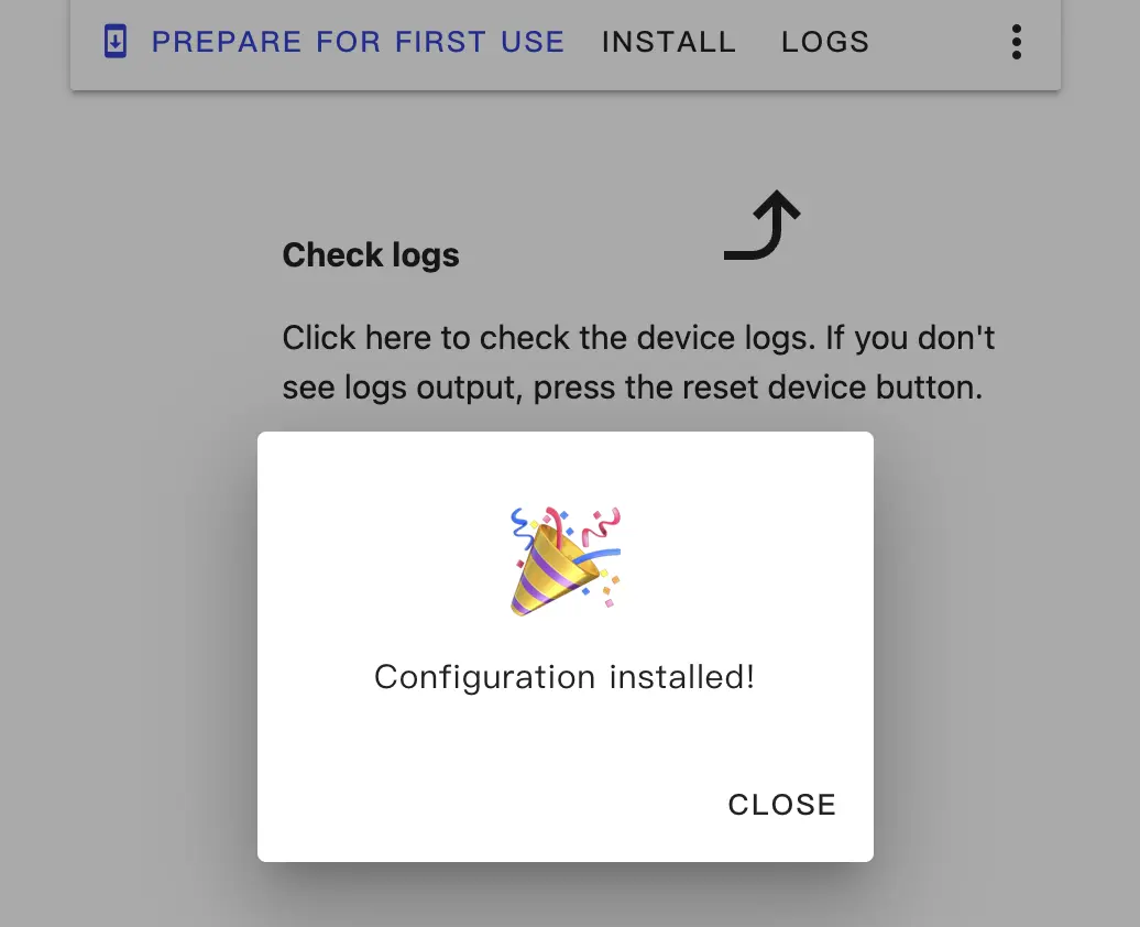
When flashing is complete, the device will automatically reset.
Getting Started
Add Device to Home Assistant Integration
When the device restarts, it will automatically connect to the previously configured network. Under normal circumstances, the device can be discovered in
Settings->Devices & services.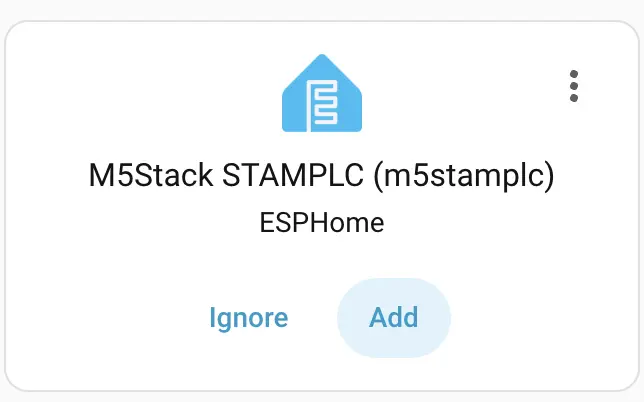
Click
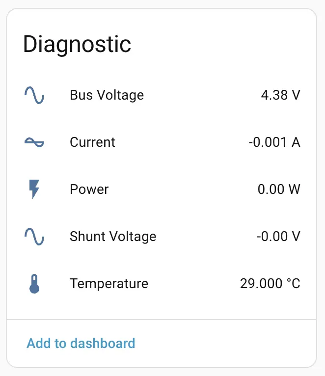
Addto integrate StamPLC into Home Assistant. If an API Encryption Key was previously set, you may need to enter it here for verification. StamPLC Dashboard Example: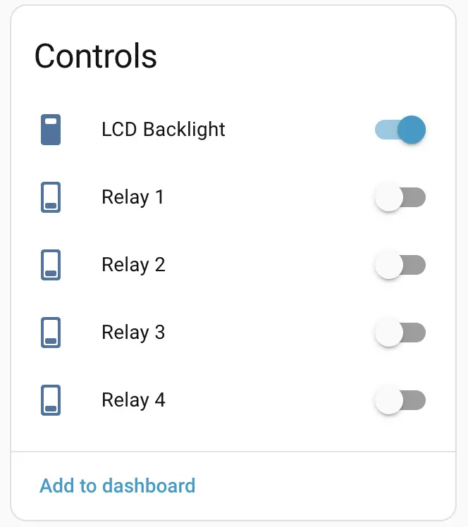
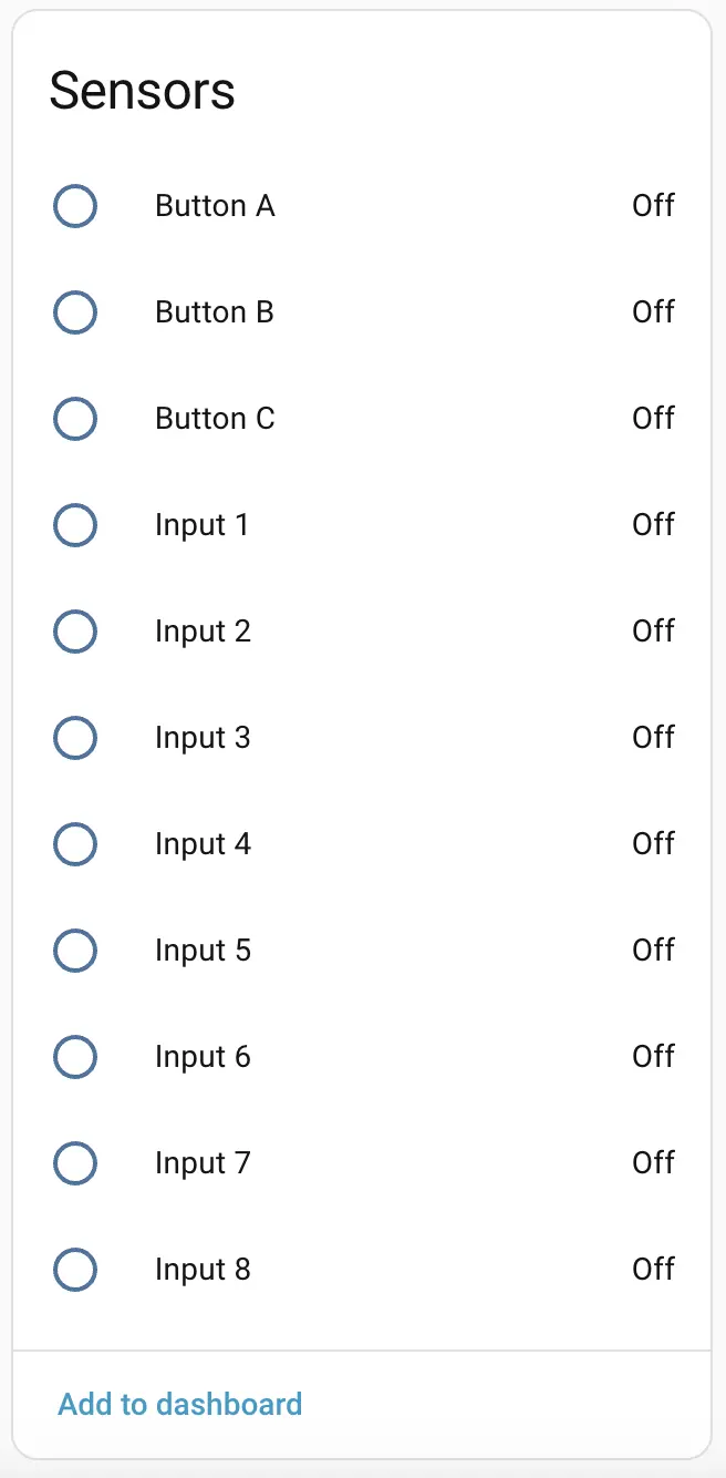
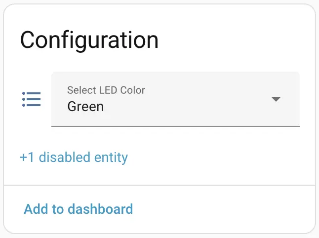
Physical Operation:
Expansion
StamPLC supports expansion, allowing other expansions to be connected via the 16-pin header on the right side.
StamPLC AC
Product Introduction:

StamPLC AC is an AC relay expansion module tailored for the StamPLC host. The module integrates AC load control and power supply for the entire machine, effectively simplifying the power wiring for applications. It uses contact relays (SPST - Normally Open), supporting line on/off up to AC 240V@10A. It has a built-in AC-DC isolated conversion circuit, supporting AC 100 ~ 240V input, which can power the relay load while outputting DC 12V to power the entire machine. Onboard programmable tri-color LED for status indication. The StamPLC main controller programs and controls the relays and RGB LED via an I2C IO expansion chip, effectively saving IO resources. Suitable for industrial application scenarios such as AC load equipment switches and solenoid valve control.
Configure StamPLC AC: Based on the previous StamPLC configuration, some components need to be added to the YAML configuration:
Add new IO Expander:
pi4ioe5v6408: - id: pi4ioe5v6408_1 address: 0x43 # Configuration of i2c GPIO Expander 2 # on the StamPLC AC expansion - id: pi4ioe5v6408_2 address: 0x44Add new AC Relay switch:
switch: ... - platform: gpio restore_mode: RESTORE_DEFAULT_OFF name: "StamPLC AC Relay" id: ac_r1 pin: pi4ioe5v6408: pi4ioe5v6408_2 number: 2 mode: output: true on_state: - component.update: vduAdd new LED color control on top of AC Relay:
switch: ... # led indicator on StamPLC AC expansion - platform: gpio restore_mode: ALWAYS_OFF id: "ac_relay_led_red" pin: pi4ioe5v6408: pi4ioe5v6408_2 number: 5 inverted: true mode: output: true - platform: gpio restore_mode: ALWAYS_OFF id: "ac_relay_led_green" pin: pi4ioe5v6408: pi4ioe5v6408_2 number: 6 inverted: true mode: output: true - platform: gpio restore_mode: ALWAYS_OFF id: "ac_relay_led_blue" pin: pi4ioe5v6408: pi4ioe5v6408_2 number: 7 inverted: true mode: output: trueAdd new AC Relay UI for the Display component:
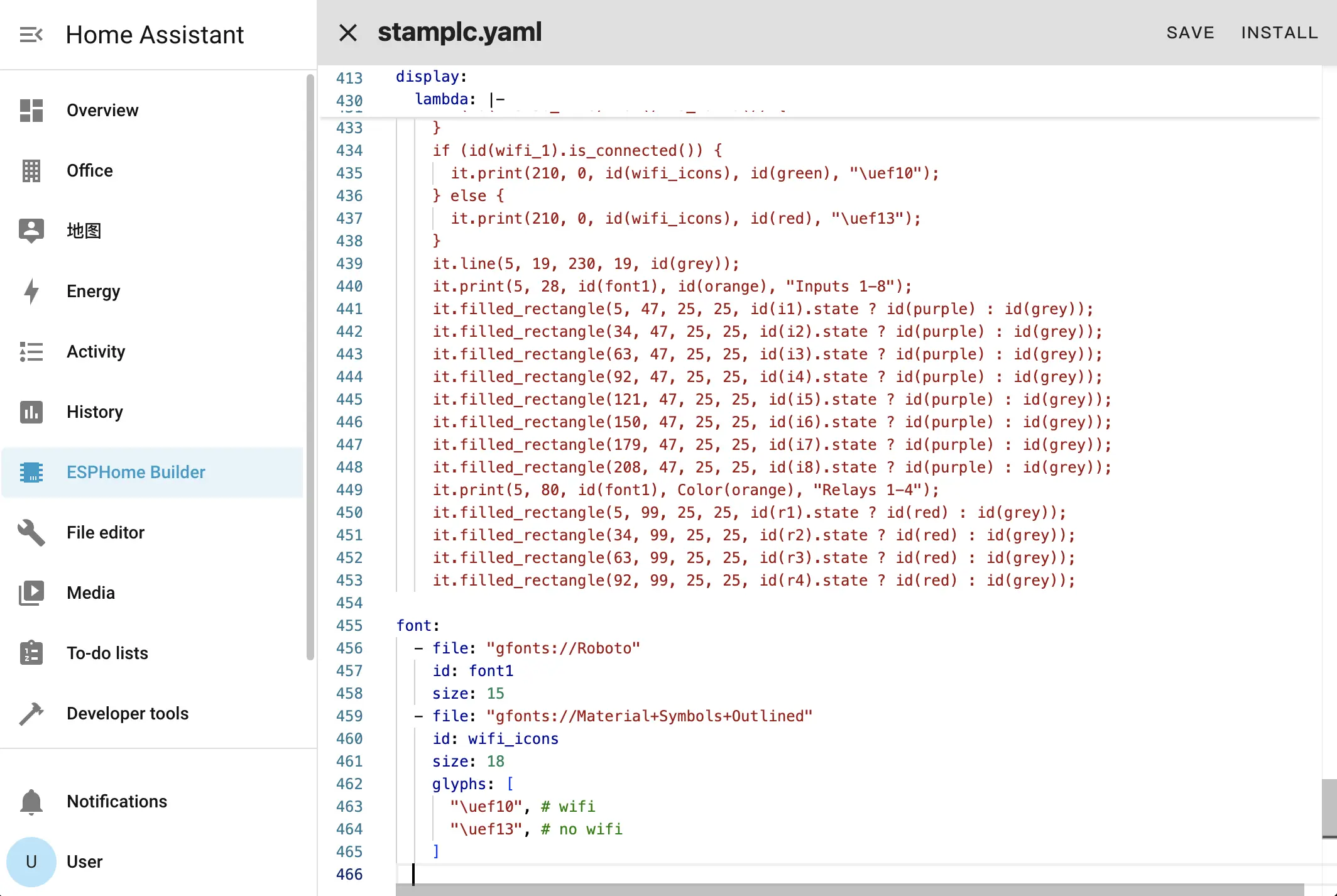
display:
  ...
  lambda: |-
    ...
    it.print(5, 80, id(font1), Color(orange), "Relays 1-4");
    it.filled_rectangle(5, 99, 25, 25, id(r1).state ? id(red) : id(grey));
    it.filled_rectangle(34, 99, 25, 25, id(r2).state ? id(red) : id(grey));
    it.filled_rectangle(63, 99, 25, 25, id(r3).state ? id(red) : id(grey));
    it.filled_rectangle(92, 99, 25, 25, id(r4).state ? id(red) : id(grey));
    it.print(141, 80, id(font1), Color(orange), "AC Expansion");    // The AC Relay Expansion
    it.filled_rectangle(141, 99, 25, 25, id(ac_r1).state ? id(red) : id(grey));
  ...
After completing the configuration, recompile and upload the firmware. Add the device to Home Assistant to control the AC Relay via the additional switch.

Turning the switch on and off will change the LCD status synchronously.
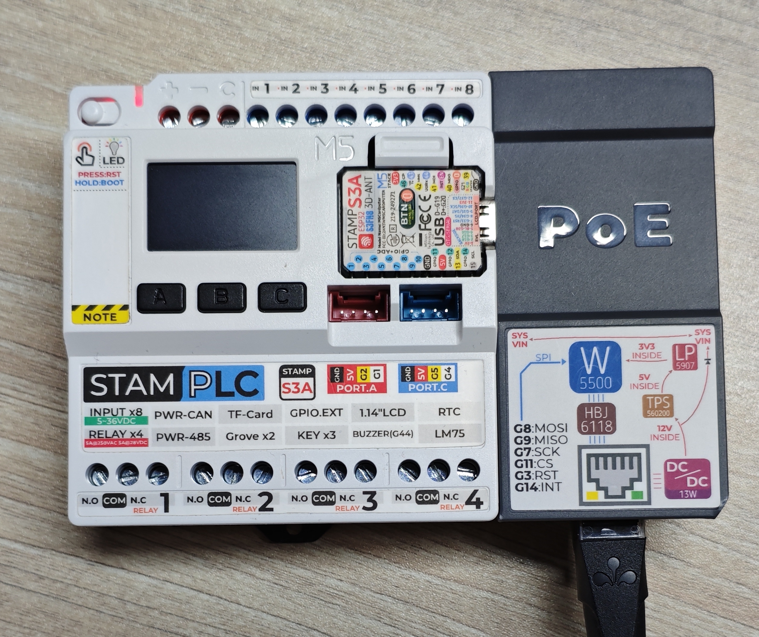
StamPLC PoE
Product Introduction:
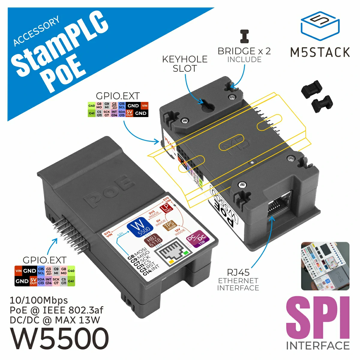
StamPLC PoE is an Ethernet control module for the StamPLC host, supporting PoE (Power over Ethernet) technology, which allows simultaneous data transmission and power supply through a single network cable. The module has a built-in W5500 embedded Ethernet controller, integrating the TCP/IP protocol stack, with 8 independent hardware sockets, 10/100M Ethernet Data Link Layer (MAC), and Physical Layer (PHY), supporting mainstream network communication methods such as UDP and TCP.
Configure StamPLC PoE:
In network components, the 'wifi' component and 'ethernet' component are mutually exclusive options; you can only choose one.
To use the PoE function, you need to disable the wifi, display, and spi components (delete related declarations/definitions in the configuration file), then add to the original configuration file:
ethernet:
  id: ethernet_1
  type: W5500
  clk_pin: GPIO7
  mosi_pin: GPIO8
  miso_pin: GPIO9
  cs_pin: GPIO11
clock_speed: 20MHzSave and recompile, upload the project. Use a PoE switch or router to provide power and network to the device.