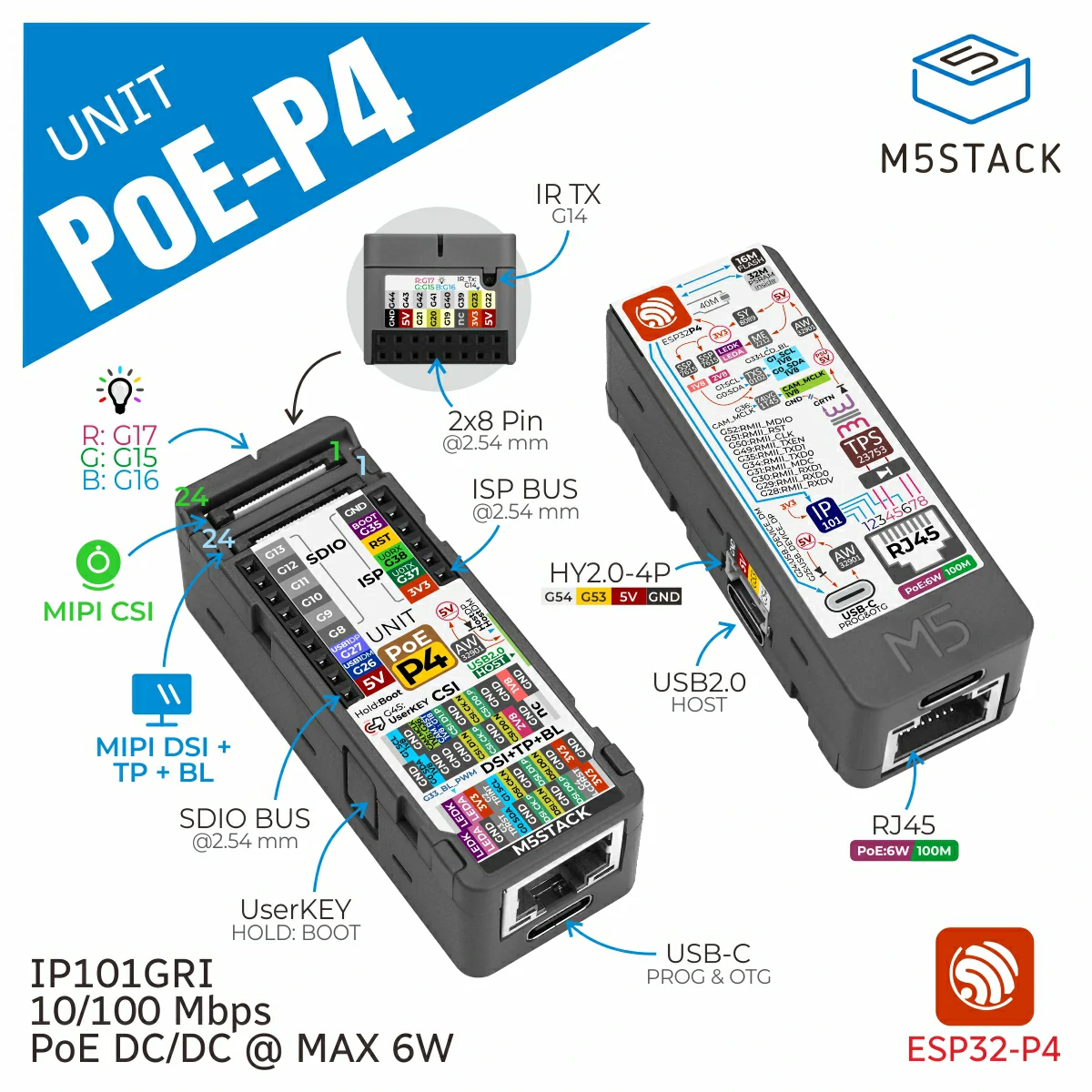
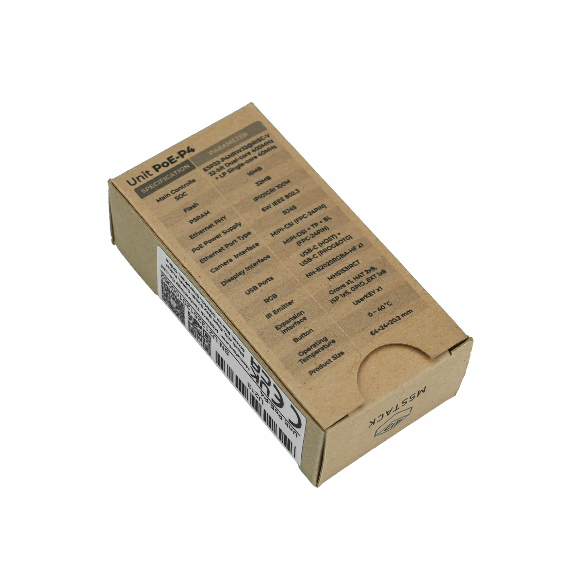
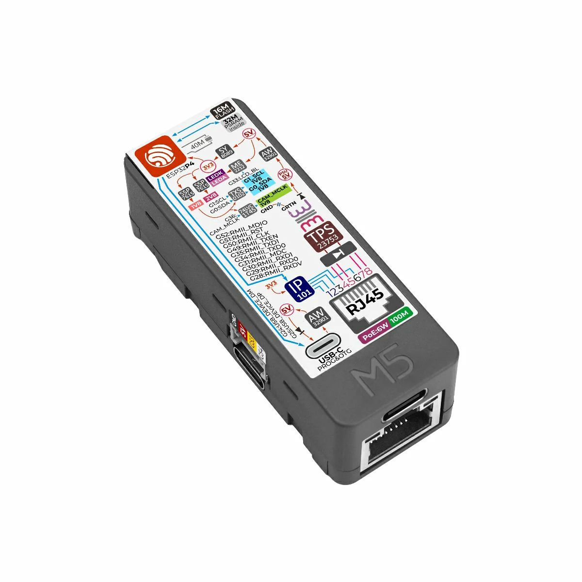
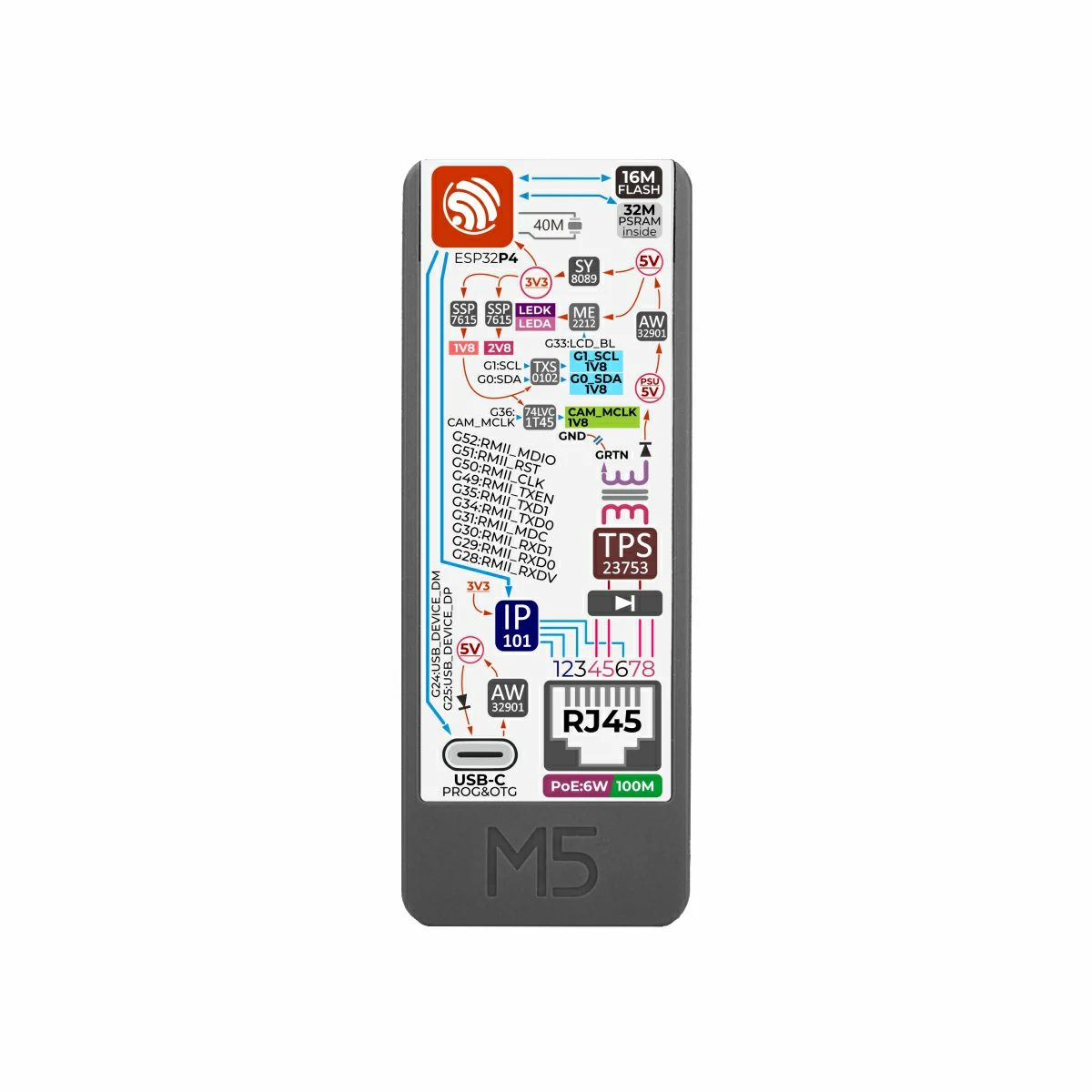
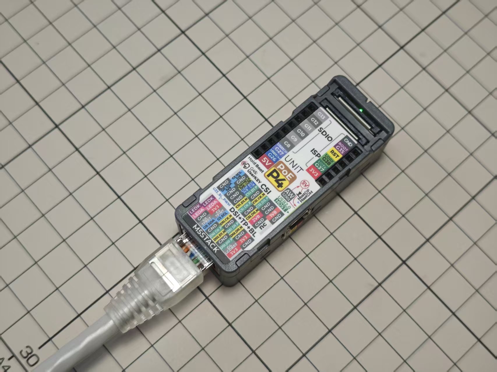
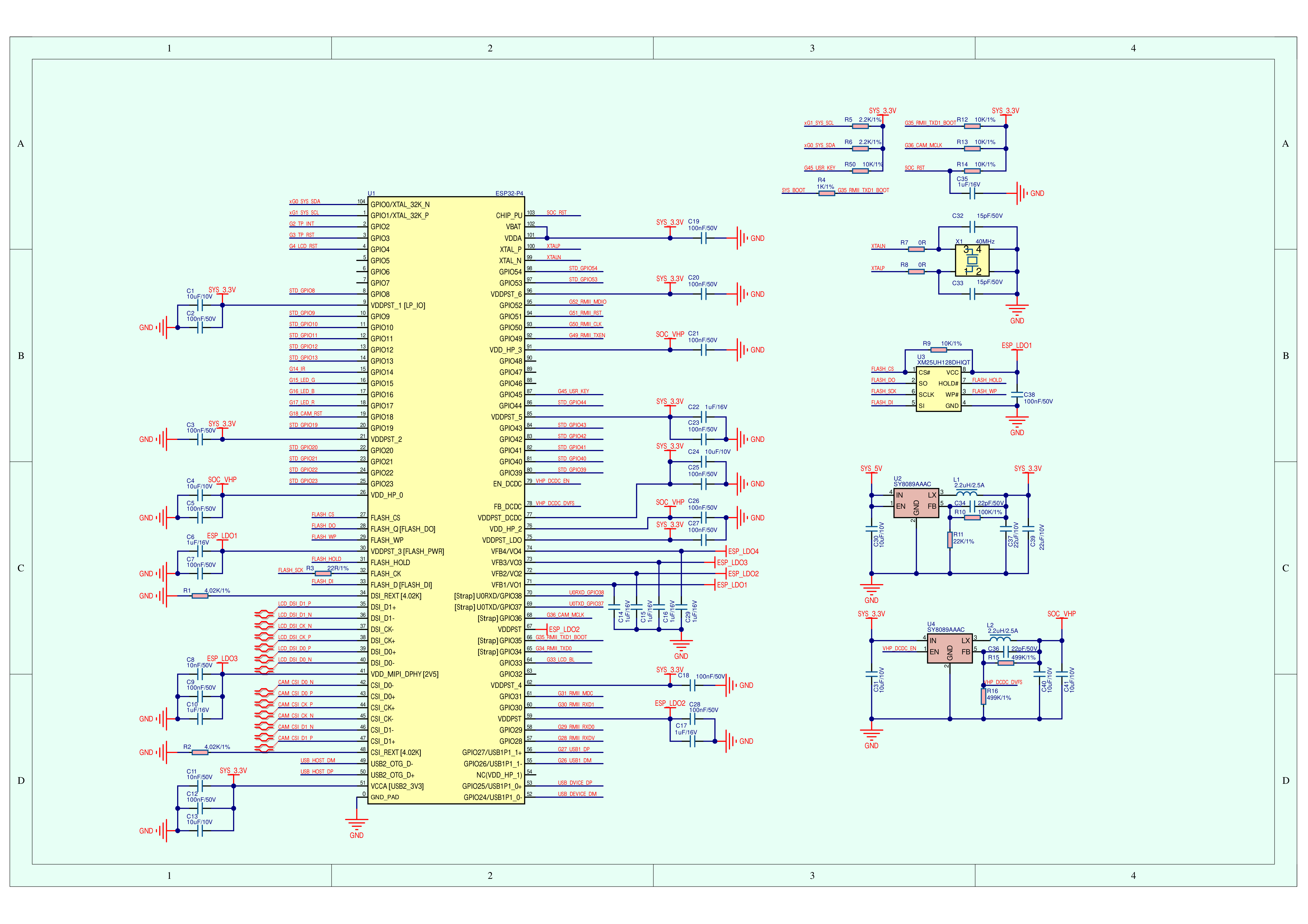
Unit PoE‑P4 is a high‑performance PoE Ethernet embedded controller powered by the ESP32‑P4 SoC (RISC‑V 32‑bit dual‑core @ 360MHz + LP single‑core @ 40MHz). It integrates 16MB Flash and 32MB PSRAM, and features the built‑in IP101GRI Ethernet PHY supporting 10/100 Mbps communication. The device also supports PoE power delivery with a maximum output of 6W, and includes an onboard DC‑DC converter to supply system power, greatly simplifying power wiring in practical applications.
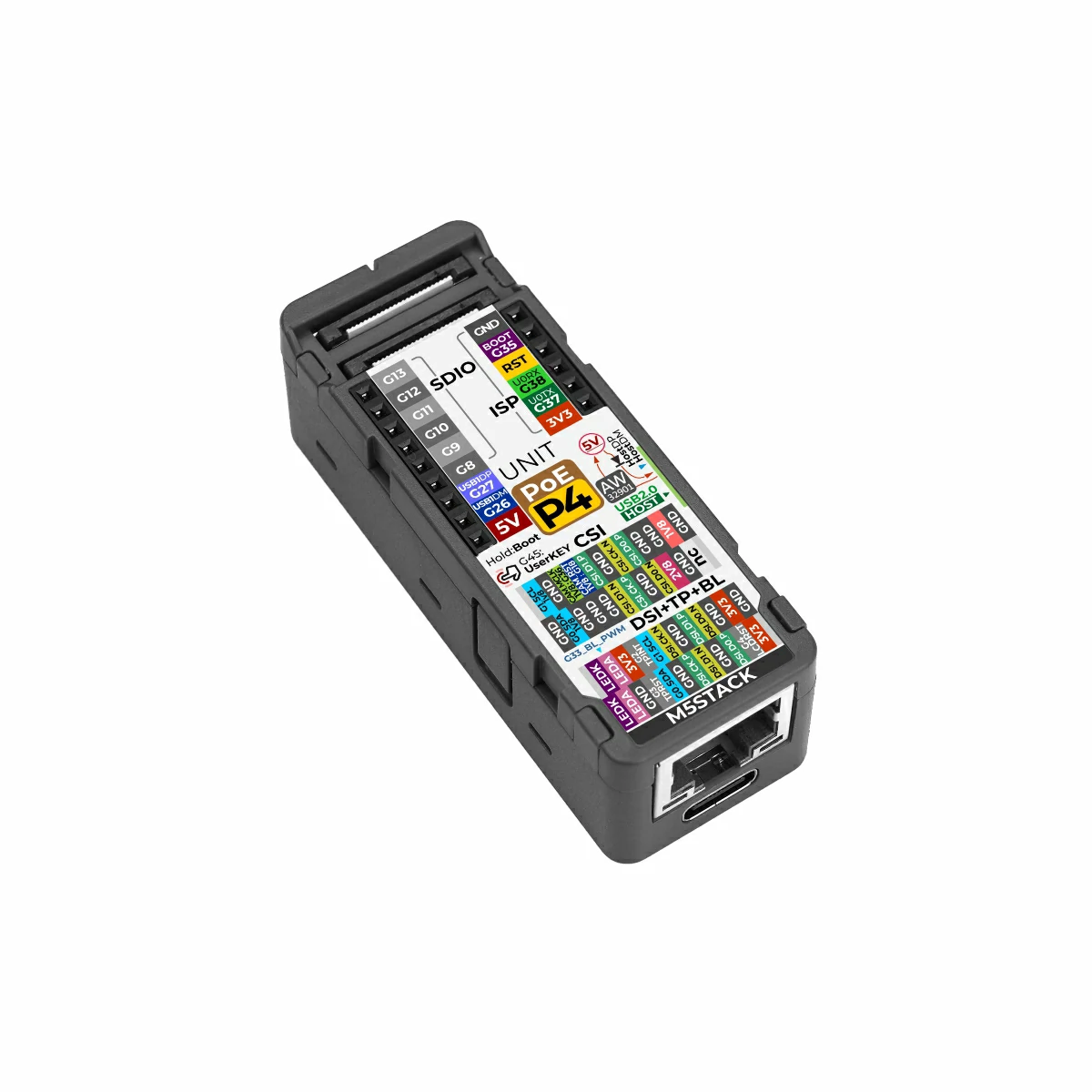
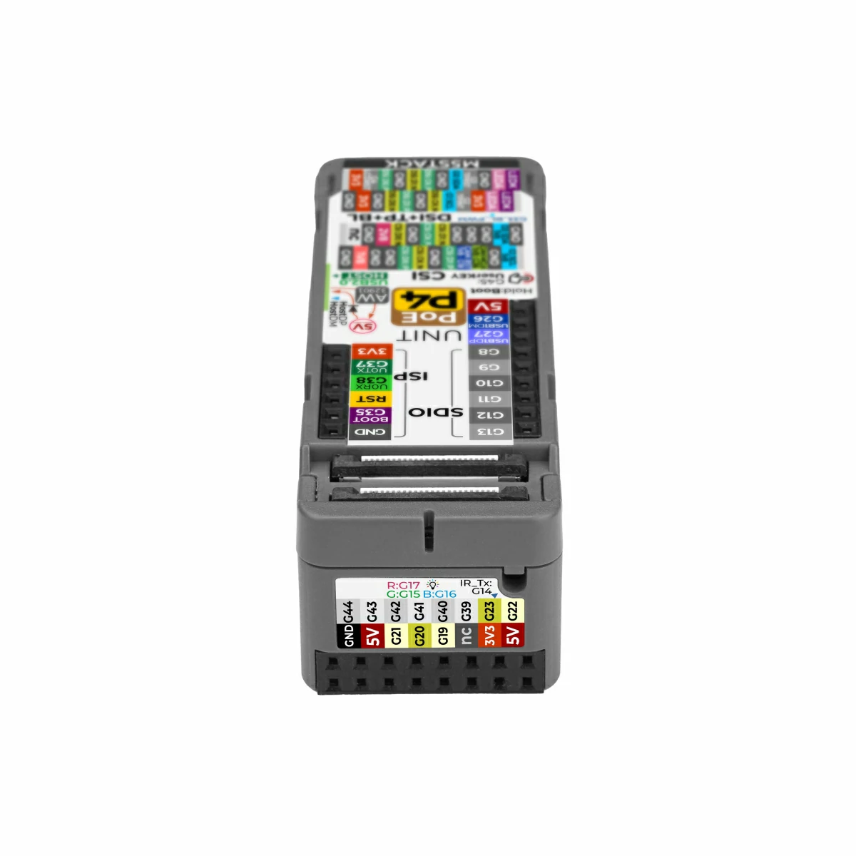
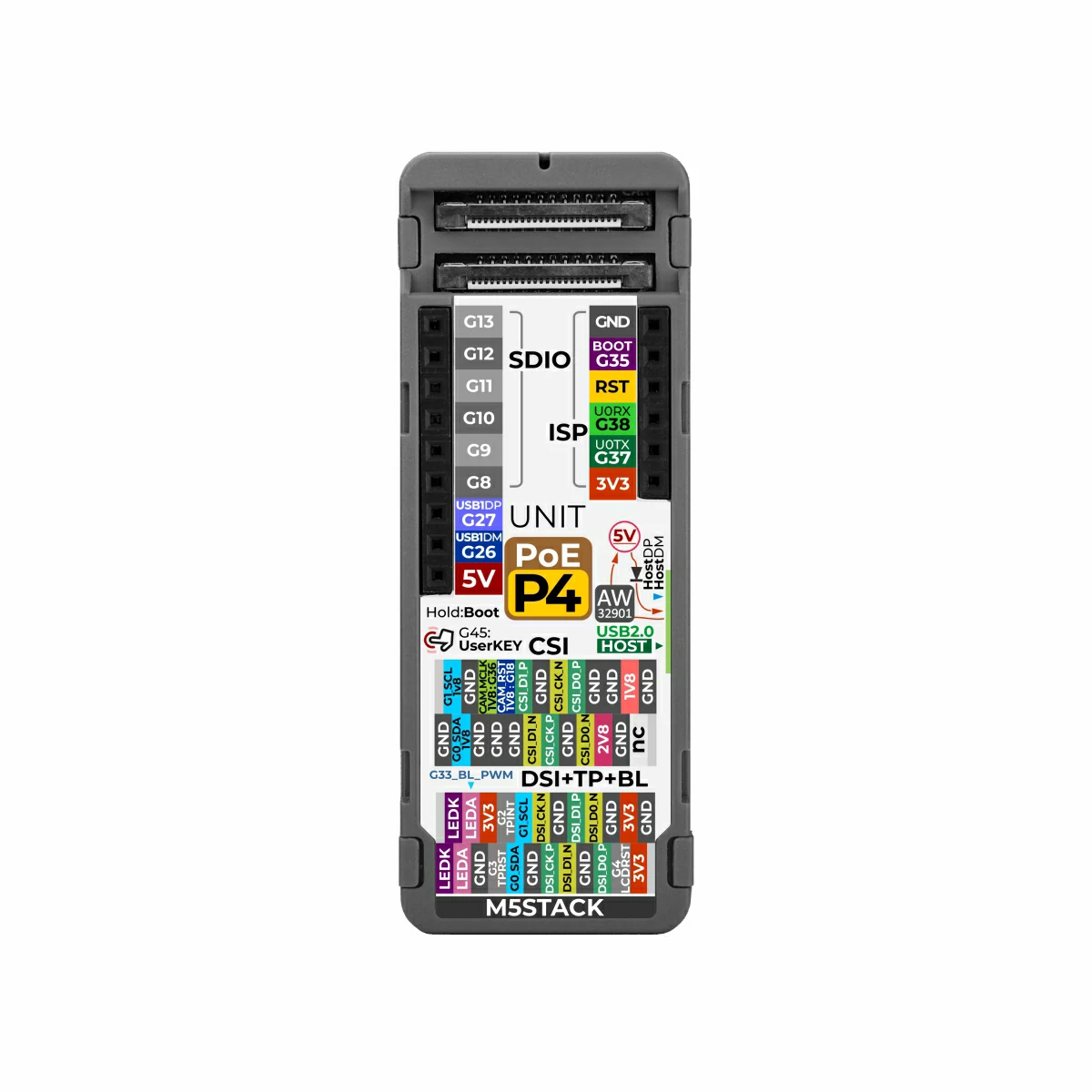
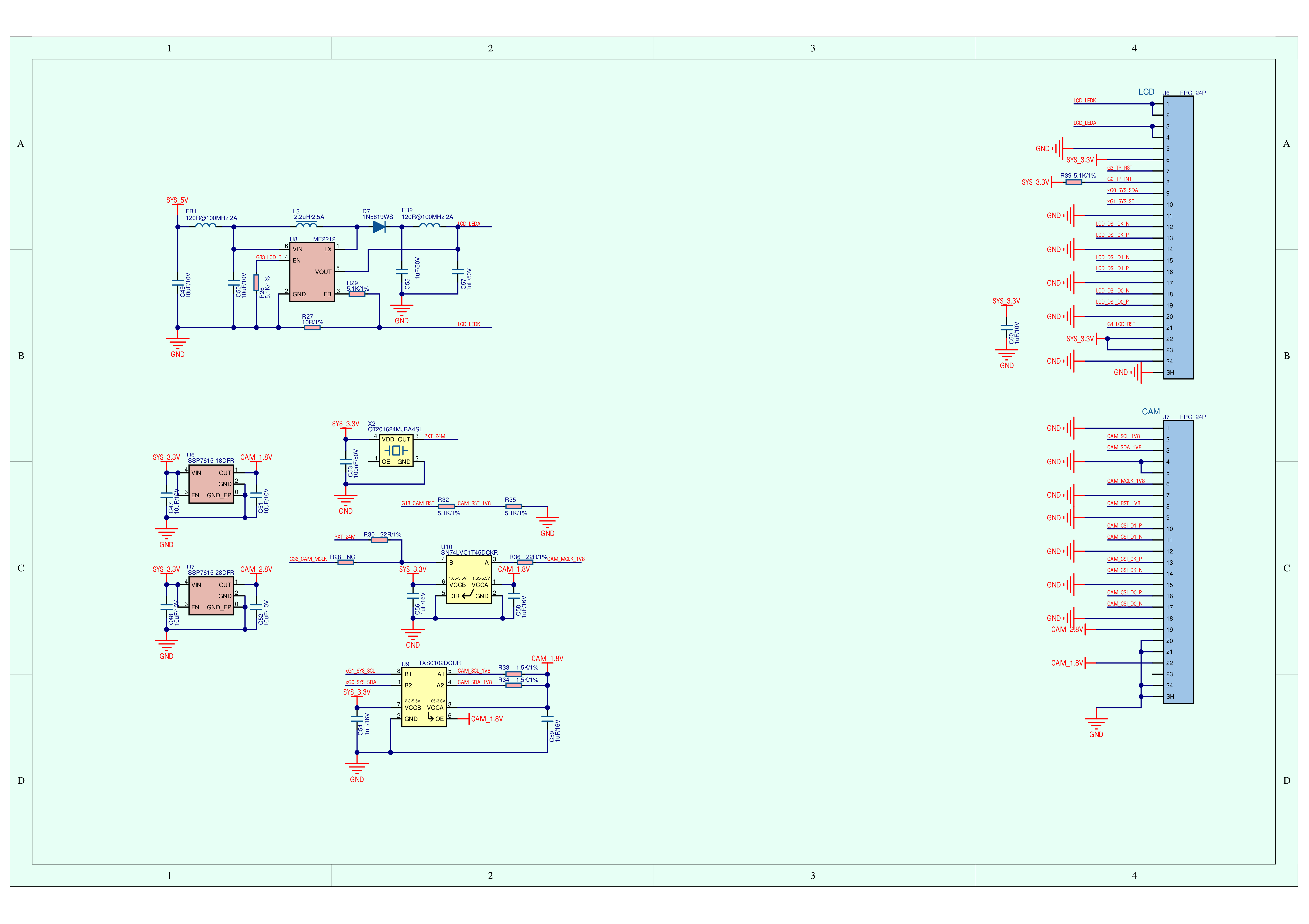
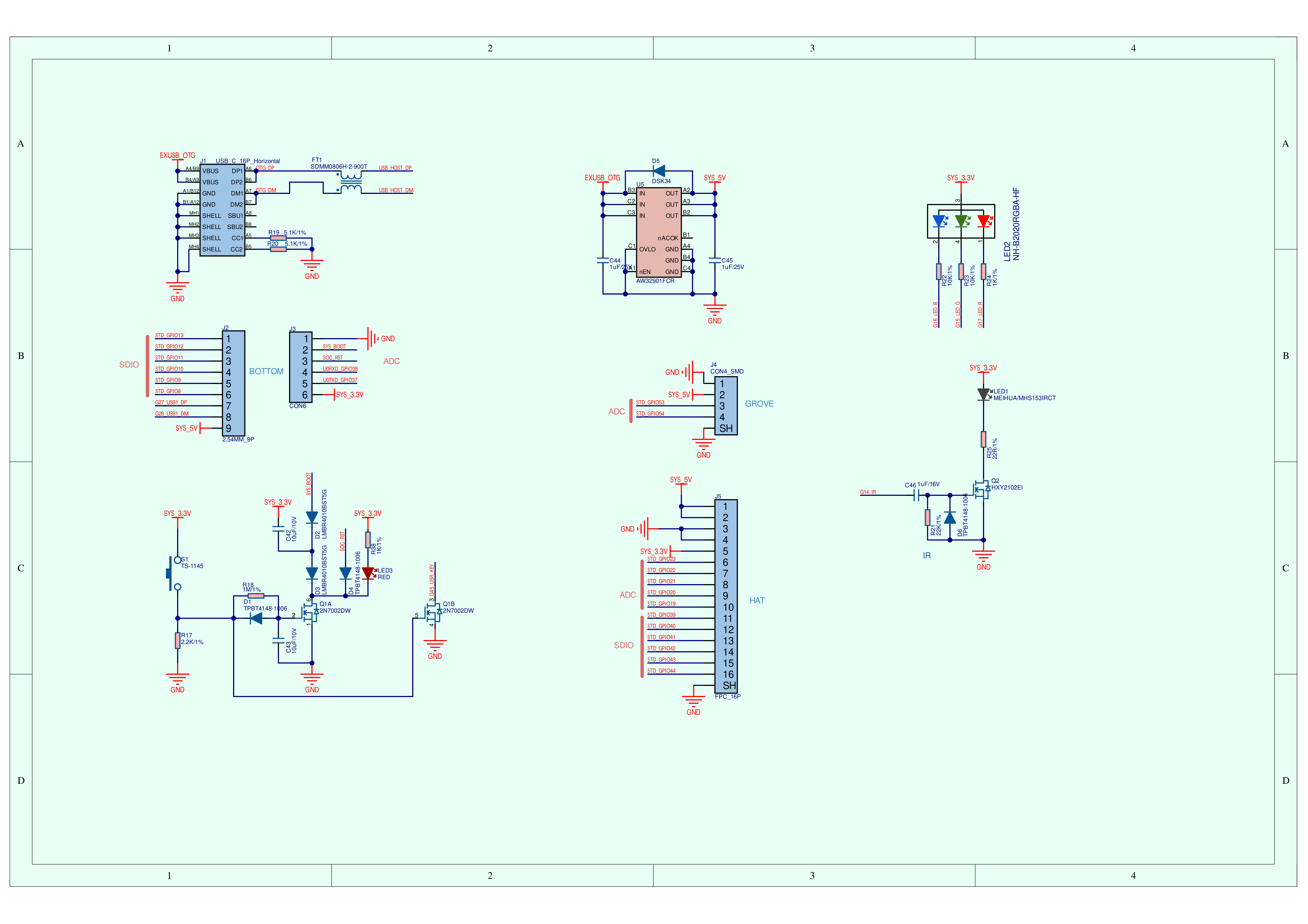
It is equipped with a 24P FPC display expansion interface (MIPI DSI + TP + BL) and a 24P FPC camera interface (MIPI CSI), supporting high‑resolution display output and image capture. For peripheral expansion, it provides one USB Type‑C Host (USB 2.0) port for connecting U disks, HID devices, and other peripherals, plus one USB Type‑C (USB 2.0) port supporting OTG and firmware download for debugging. In addition, it features a Hat expansion interface, SDIO & ISP IO expansion interfaces, and a Grove interface, enabling flexible connection to a wide range of sensors and peripherals.
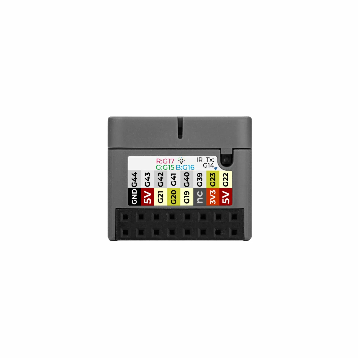
The device also integrates an RGB indicator LED, an infrared transmitter circuit, and a user button to support status indication, local interaction, and infrared signal transmission. It is ideal for applications such as industrial HMI, PoE smart terminals, vision acquisition nodes, smart home controllers, and edge computing devices.
MIPI DSI display supports up to 1920×1080 (limited by lane count and frame rate)
Camera Interface
24P FPC (0.5mm pin pitch) MIPI CSI 2‑Lane
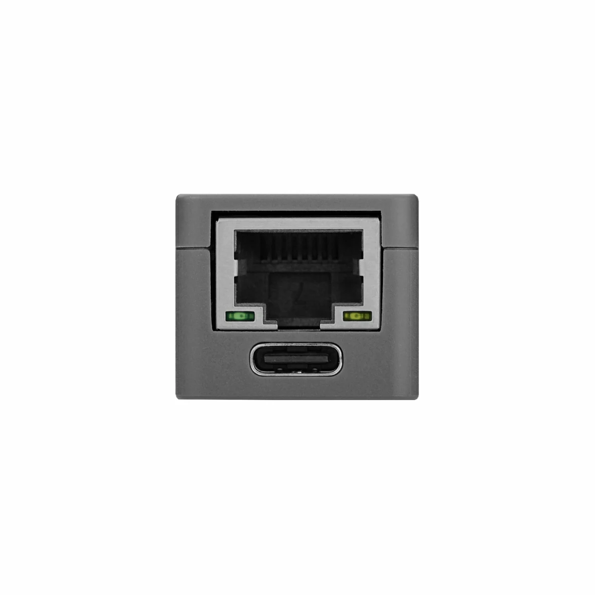
USB Type‑C
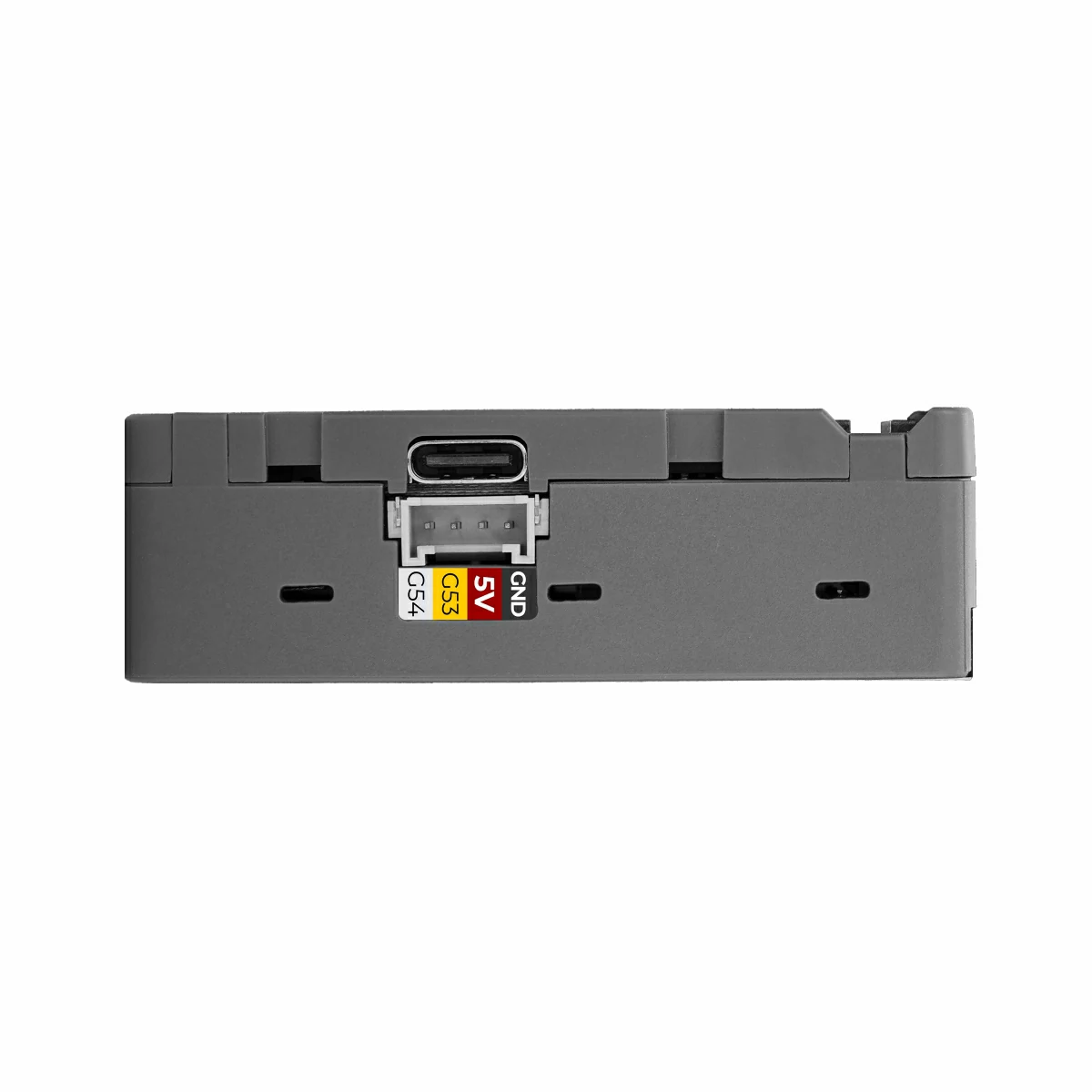
1x USB Type‑C Host interface (USB 2.0) 1x USB Type‑C firmware download / OTG interface (USB 2.0)
Power Consumption
Operating current: 5V @ 73.82mA Infrared transmission: 3.3V @ 23.57mA (instantaneous) RGB: 5V @ 75.32mA Full load (display, camera, IR, RGB, etc.): 277.10mA Deep sleep: 5V @ 19.85mA
RGB LED
1 x NH-B2020RGBA-HF
Infrared Transmitter
1 x MHS153IRCT
Operating Temperature
0 ~ 40°C
Product Size
64.0 x 24.0 x 20.2mm
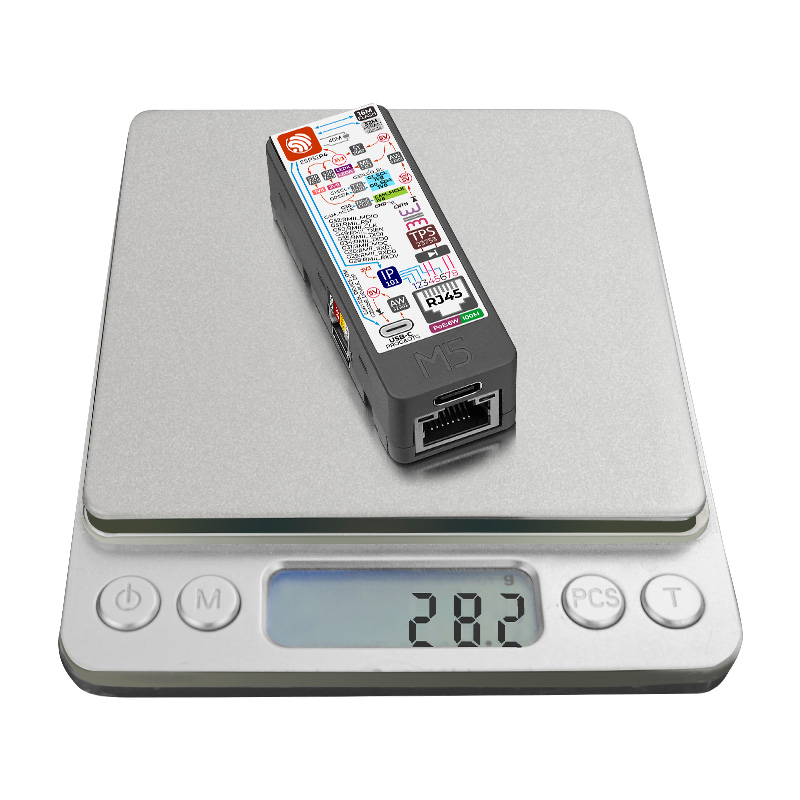
Product Weight
28.2g
Package Size
65.0 x 33.0 x 21.2mm
Gross Weight
35.0g
Learn
Download Mode
To flash firmware, connect the device to a computer via a USB Type‑C data cable. Press and hold the side button for 3 seconds until the green LED lights up. The device will then enter download mode and wait for firmware flashing.
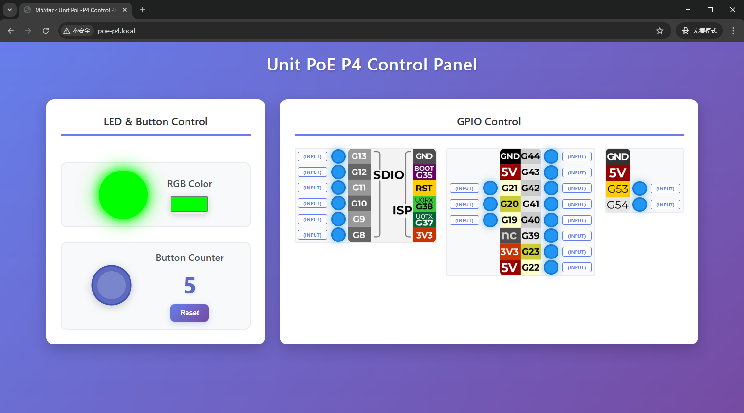
Access Device Control Page
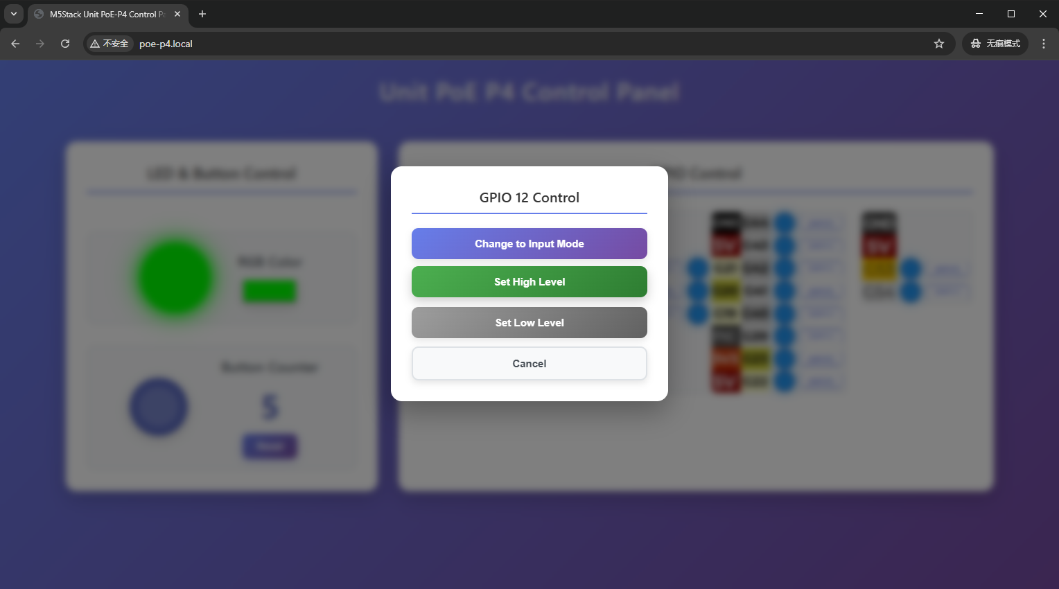
The factory default firmware of the device is preloaded with a WEB control panel, which supports RGB LED color control, button press count statistics, GPIO pin mode switching, and high/low level output. The device control page can be accessed by following these steps:
Power on the Unit PoE-P4 and connect it to the Ethernet network.
Open the serial monitor and note the device’s current IP address.
Ensure your computer or mobile phone is on the same local area network (LAN) as the device.
Access the web control page using one of the following methods:
Enter poe-p4.local in your browser
Copy the IP address shown in the serial monitor and paste it into the browser address bar