ESP-IDF Quick Start
Devices & Examples
Core2
CoreS3
Dial
Tab5
Zigbee
AddOn Display In For PoE-P4 ESP-IDF Example Program Tutorial
This tutorial explains how to build the example program for using Unit PoE-P4 with AddOn Display In For PoE-P4. Users can perform secondary development based on this example.
1. Preparation
- Environment setup: This tutorial is based on setting up the ESP-IDF development environment on Ubuntu. For instructions on setting up the build environment on other platforms, please refer to ESP-IDF - ESP32-P4 Getting Started Guide.
v5.5.2. If a version later than v5.5.2 is used, changes to the underlying ESP-IDF MIPI DSI timing calculation logic may cause the display to flicker.- Use the git version control tool to clone the esp-idf project, switch to the specified branch, and run the script to install the required toolchains.
"." and the script in the . ./export.sh command. This command is equivalent to source ./export.sh.git clone -b v5.5.2 --recursive https://github.com/espressif/esp-idf.git
cd esp-idf
./install.sh esp32p4
. ./export.shIn addition to Unit PoE-P4 and AddOn Display In For PoE-P4, this example also uses a 5.0-inch, 1280 x 720 resolution, 24P FPC ST7123 display assembly. If you use a different display, refer to Unit PoE-P4 MIPI DSI+TP+BL FPC Interface for interface details.
The
idf.pycommands used in the following steps depend on ESP-IDF. Before running the commands, callexport.shfrom ESP-IDF to activate the relevant environment variables. For details, please refer to ESP-IDF - ESP32-P4 Getting Started Guide.
2. Example Program
Download the example source code for using Unit PoE-P4 with AddOn Display In For PoE-P4, and extract it.
Enter the
M5Unit-PoE-P4-AddOn-Display-In-Exampleproject folder and callexport.shfrom the esp-idf project to activate the relevant environment variables. (Modify the command according to the actual esp-idf path.)
cd M5Unit-PoE-P4-AddOn-Display-In-Example
. ~/.espressif/v5.5.2/esp-idf/export.sh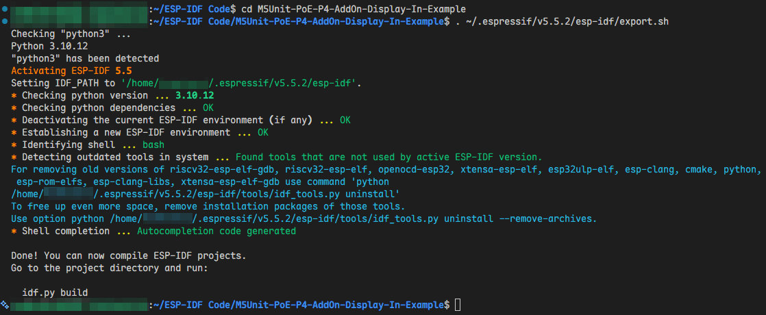
3. Build and Flash
Connect Unit PoE-P4 to the computer using a data cable. Press and hold the reset button until the green indicator lights up, then release the button. The device will enter download mode and wait for firmware flashing.
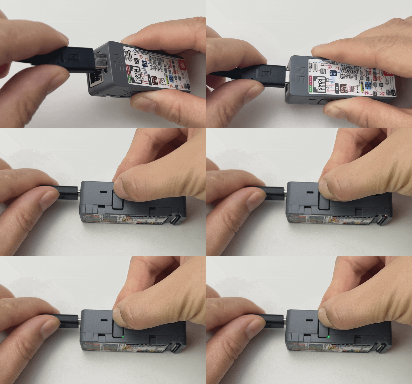
Then execute the following commands to set the target chip and port (modify the last command as needed), build, and flash the program.
idf.py set-target esp32p4
idf.py build
idf.py -p /dev/ttyACM0 flash monitor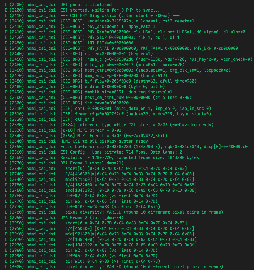
4. Getting Started
off.2. Because GPU scaling is enabled by default on Windows and macOS, the
actual output signal resolution may differ from the resolution configured in the system, which may prevent the program from working correctly:Windows: Configure the graphics driver settings so that the target resolution signal is output correctly.
macOS: Use a third-party tool (such as SwitchResX) to force the corresponding output resolution.
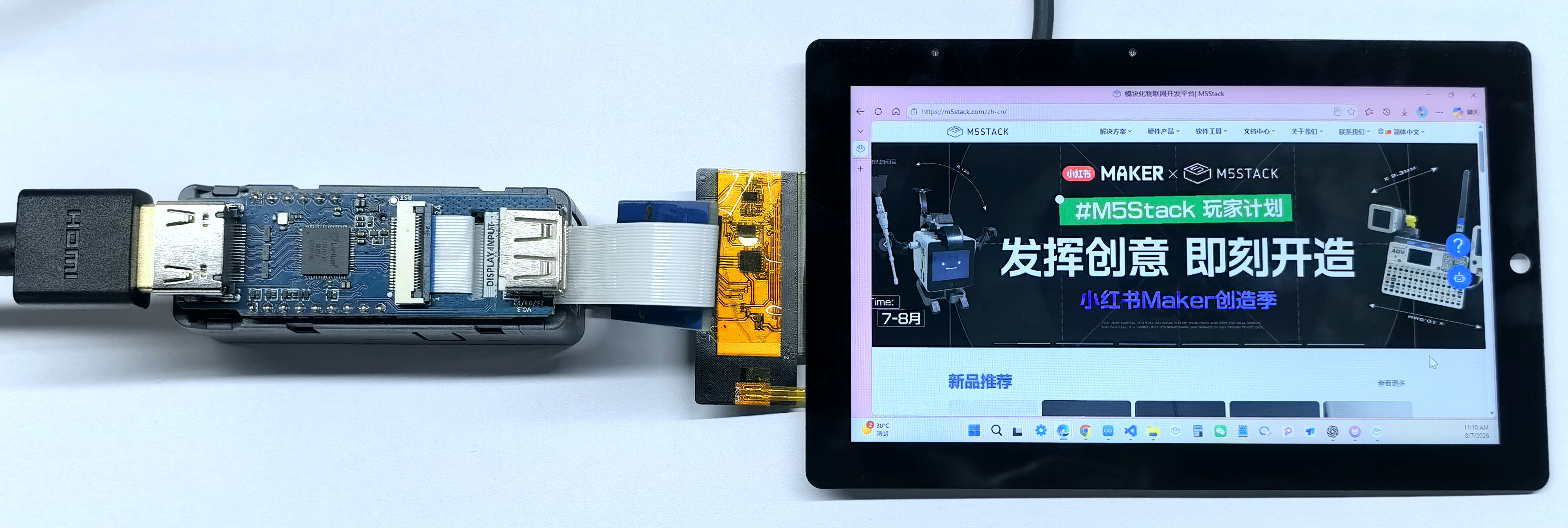
After flashing is complete, follow these steps to connect the devices and display the HDMI input image:
- Disconnect power from Unit PoE-P4.
- Connect AddOn Display In For PoE-P4 to the MIPI-CSI interface on Unit PoE-P4.
- Use a 24P FPC cable to connect the ST7123 display assembly to the MIPI-DSI interface on Unit PoE-P4.
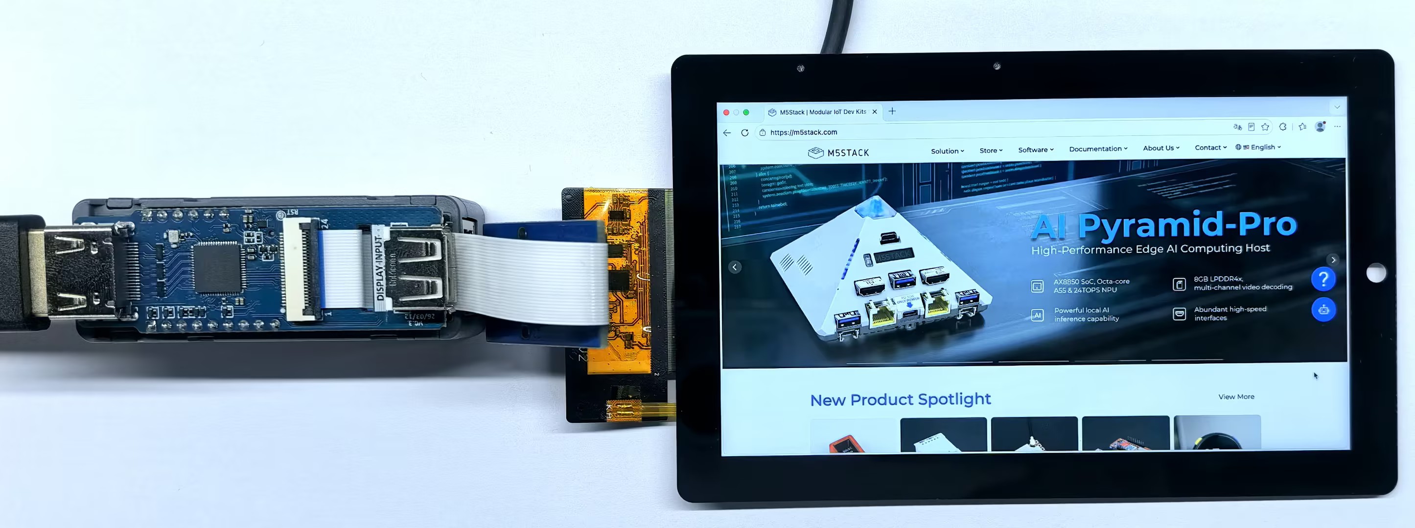
- Connect the HDMI source to the HDMI input on AddOn Display In For PoE-P4. Check the FPC cable orientation and connector locks, then power Unit PoE-P4 after confirming that all connections are correct.
- Set the actual output resolution signal to
1280 x 720 @ 60Hz.
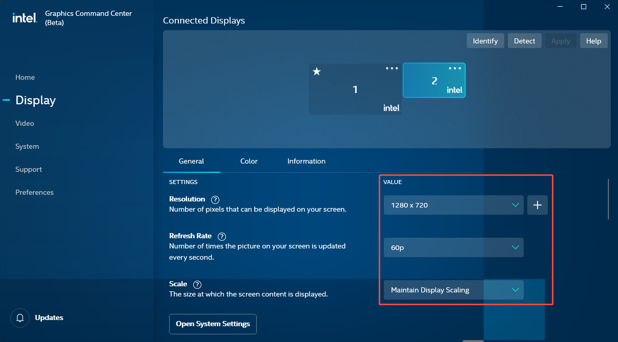
- On Windows, using an Intel integrated GPU as an example, open
Intel® Graphics Command Center (Beta)(if it is not installed, download it from the Microsoft Store), clickDisplay, and configure the settings as shown below:
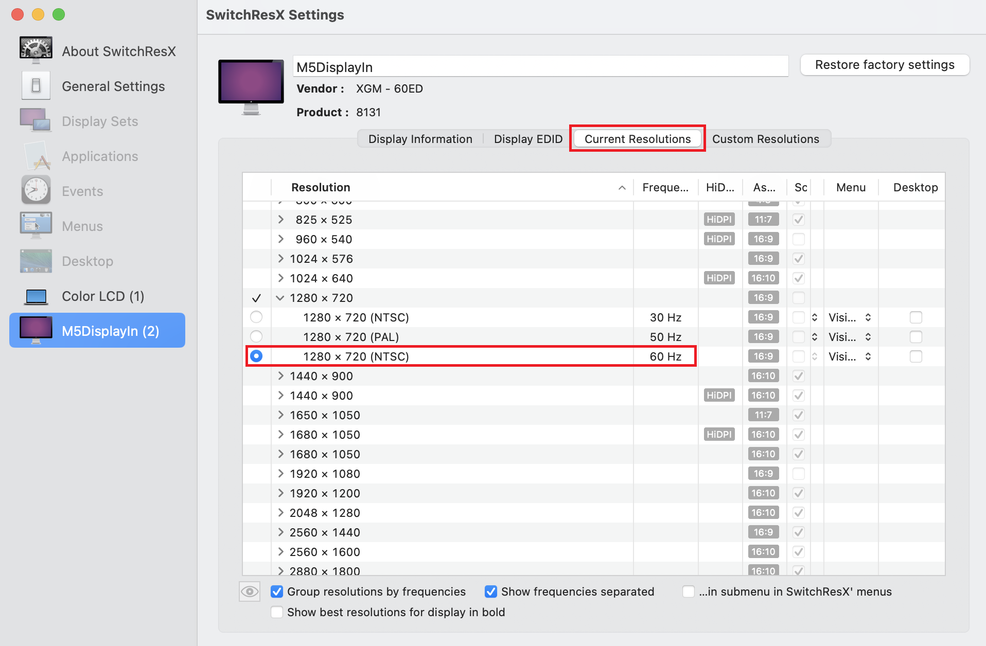
- On macOS, using a 2020 MacBook Pro as an example, download SwitchResX, open the application, click
M5DisplayIn->Current Resolutions, and select1280 x 720in the Resolution column:
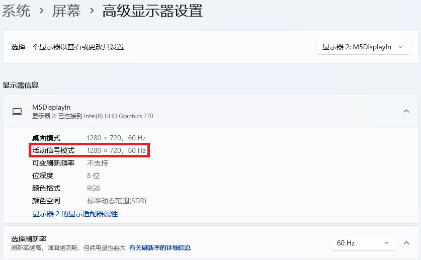
- After the settings are applied successfully, the display works normally on macOS. On Windows, confirm that the
Active signal moderesolution appears as shown below.
This example uses LT6911D to convert the HDMI input signal into 2-Lane MIPI-CSI YUYV422 data, supporting two input resolutions: 1280 x 720 @ 60Hz and 1920 x 1080 @ 30Hz. ESP32-P4 configures the CSI controller according to the valid resolution and MIPI-CSI Lane rate detected by LT6911D, then writes complete image frames to PSRAM through CSI DMA. At 1280 x 720 @ 60Hz, the full image is displayed. At 1920 x 1080 @ 30Hz, a 1280 x 720 region is cropped from the center of the image without scaling. The program then uses both CPU cores to convert YUYV422 to BGR565, rotates the image 90° counterclockwise through PPA, and finally outputs it through 2-Lane MIPI-DSI to the 720 x 1280 ST7123P display. The actual CSI DMA capture frame rate is indicated by the Status: DMA=... (... FPS) serial log. The MIPI-DSI display scan refresh rate is independent of the HDMI input refresh rate.
- Windows
- macOS