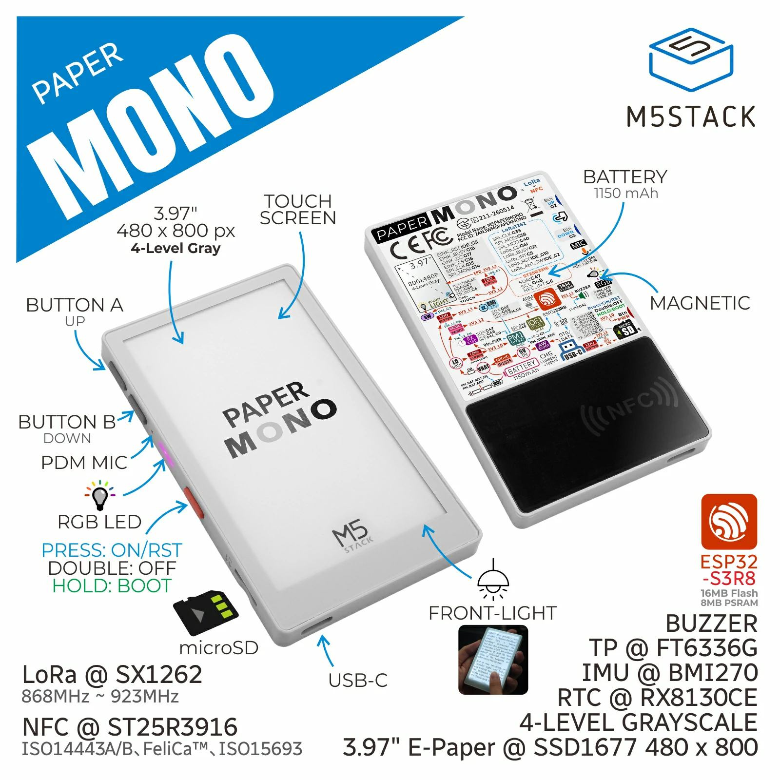
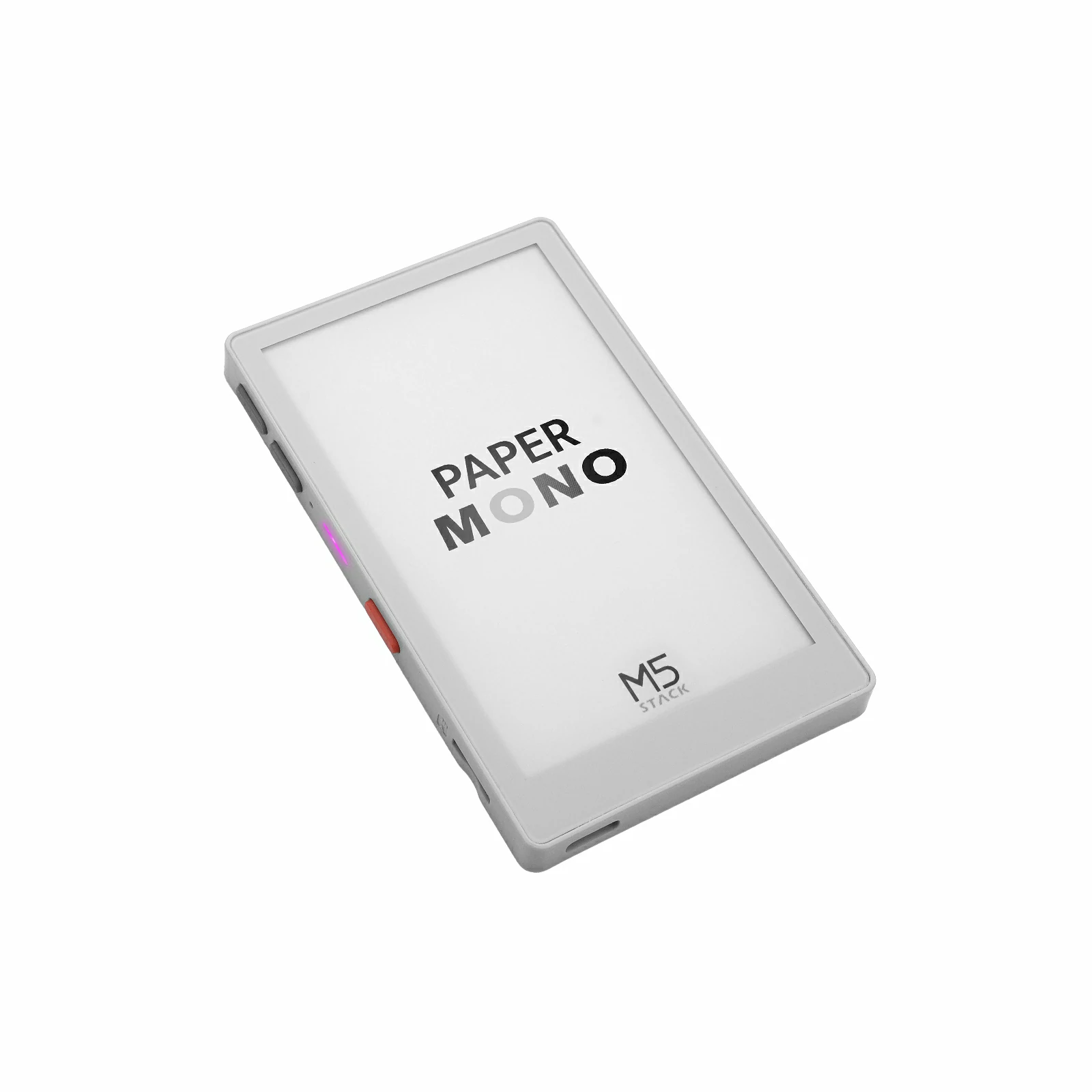
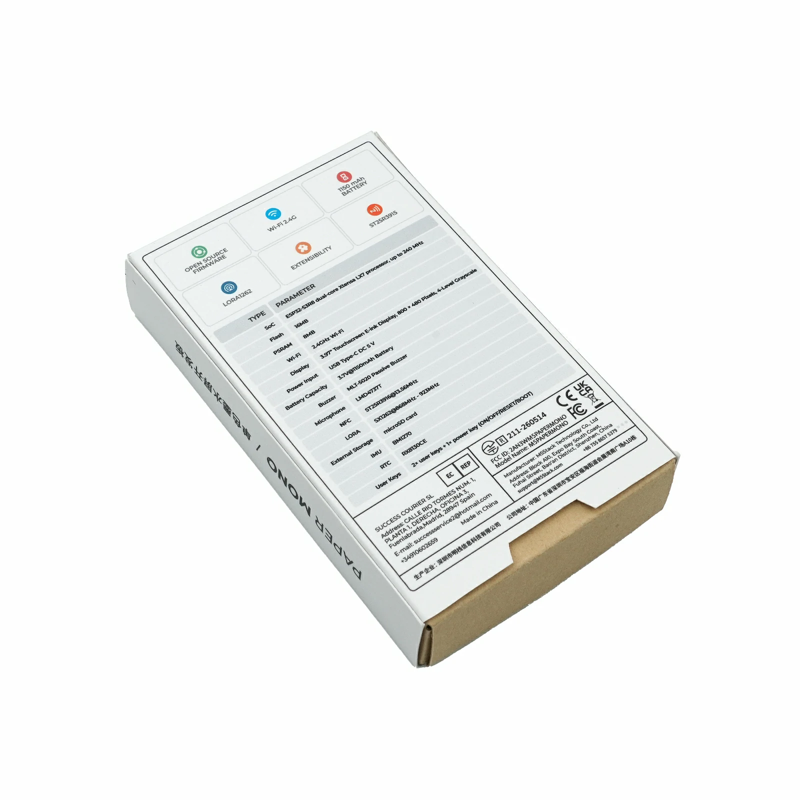
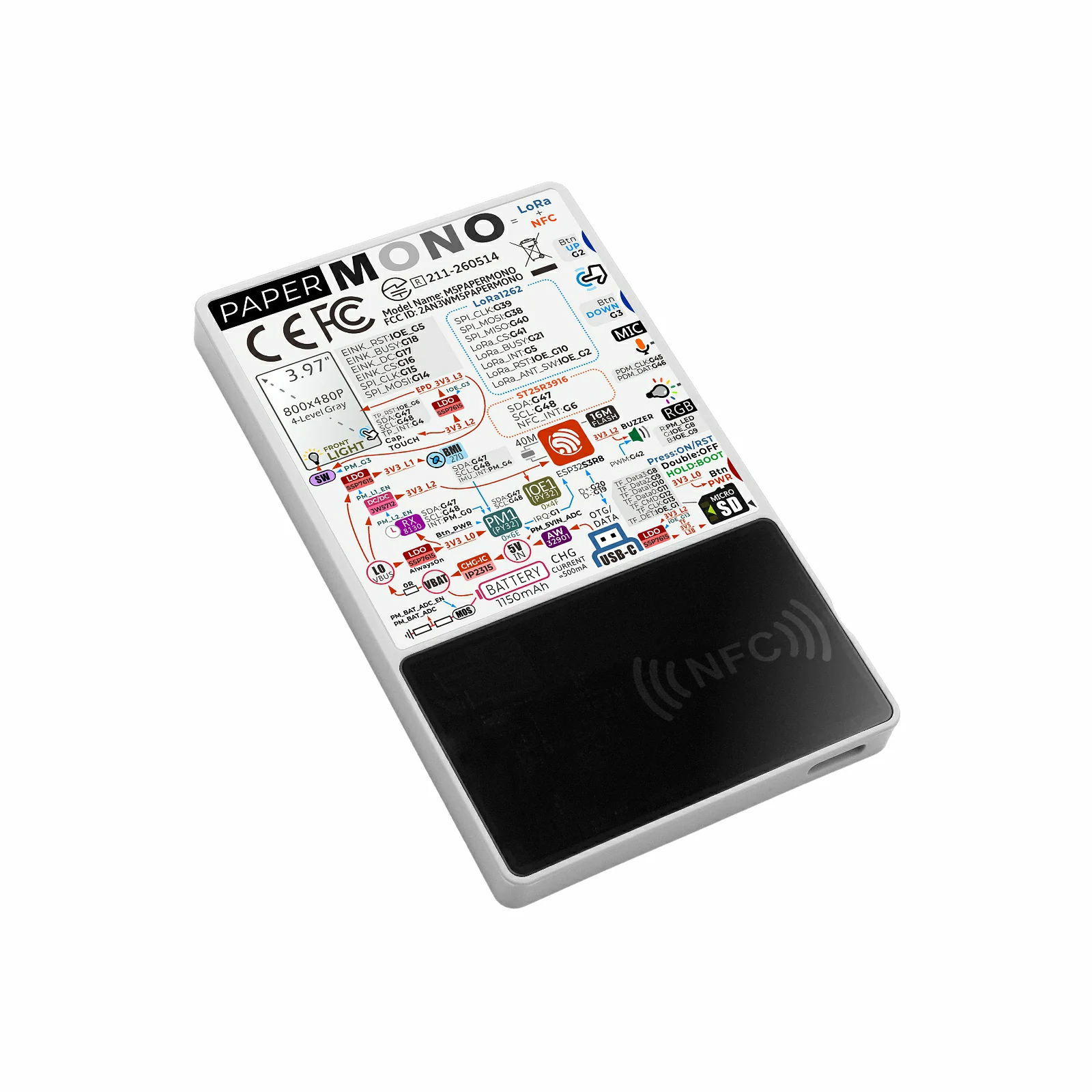
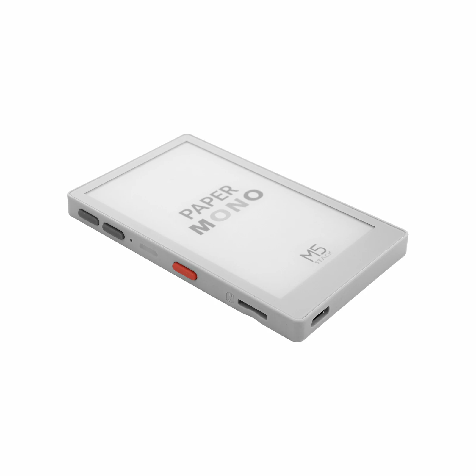
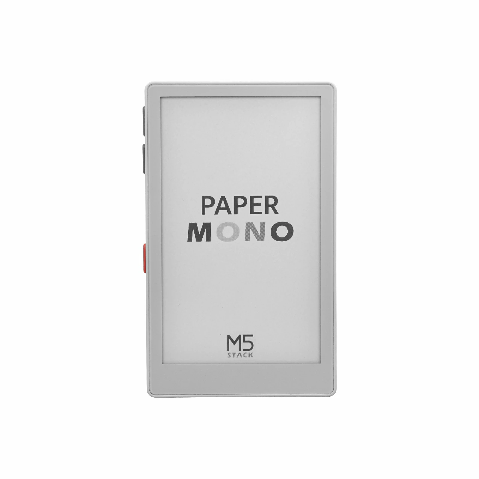
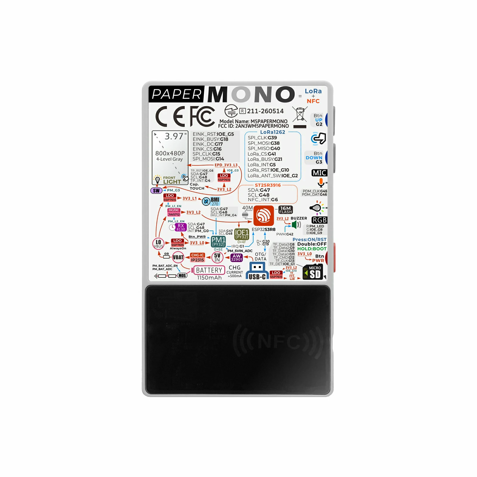
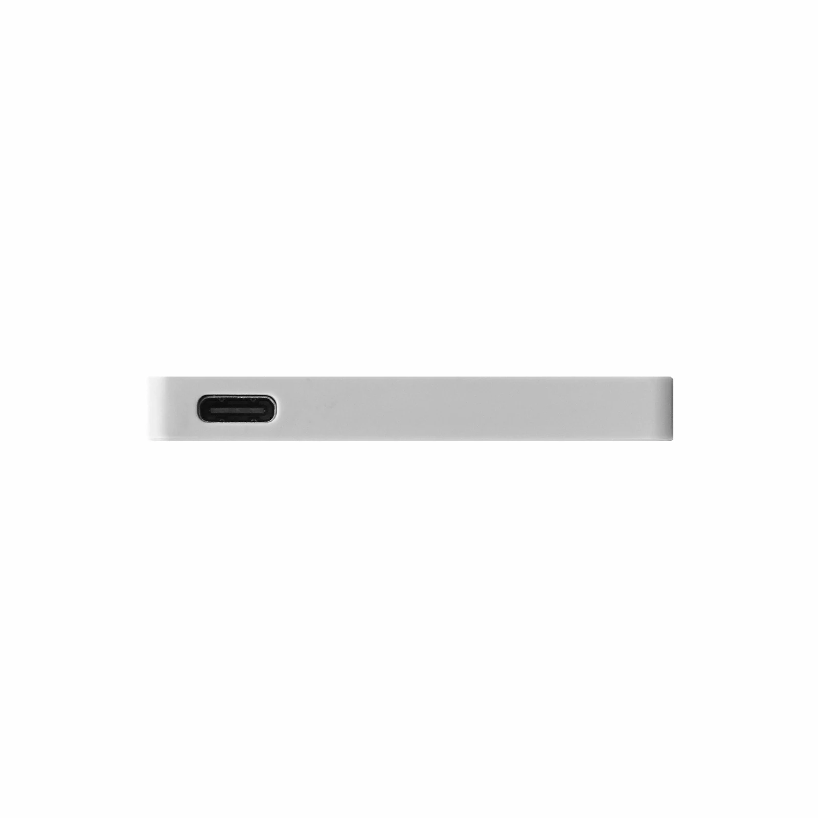
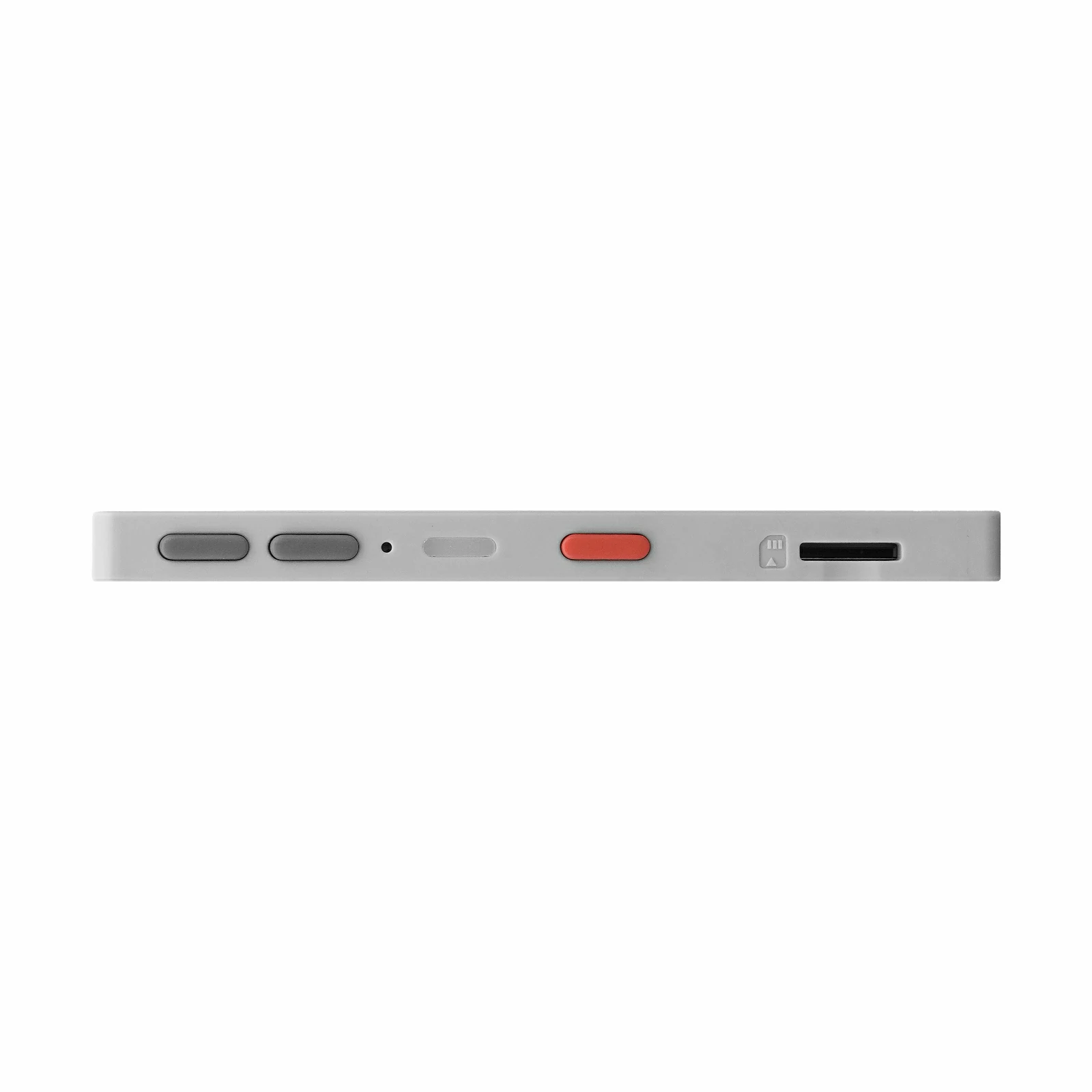
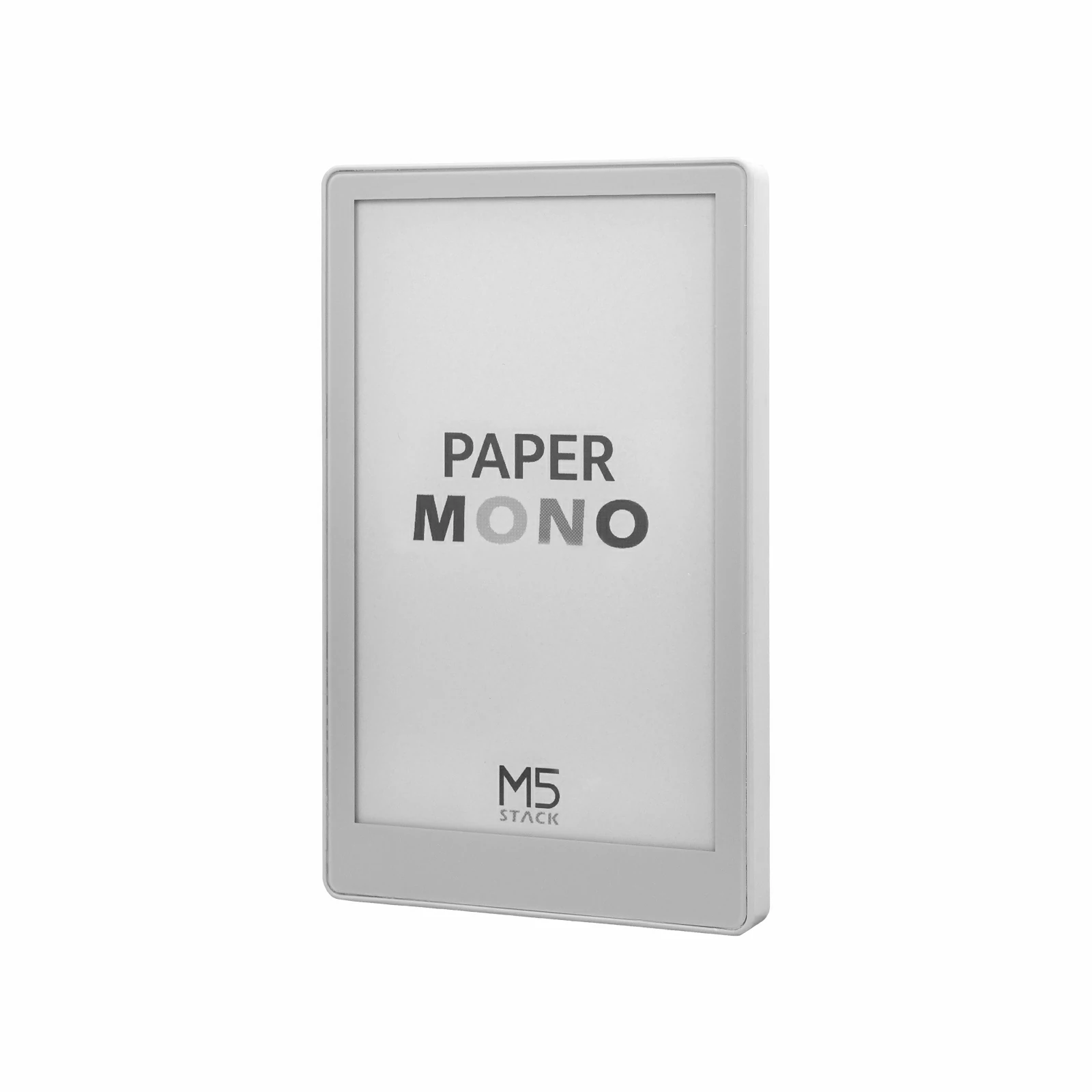
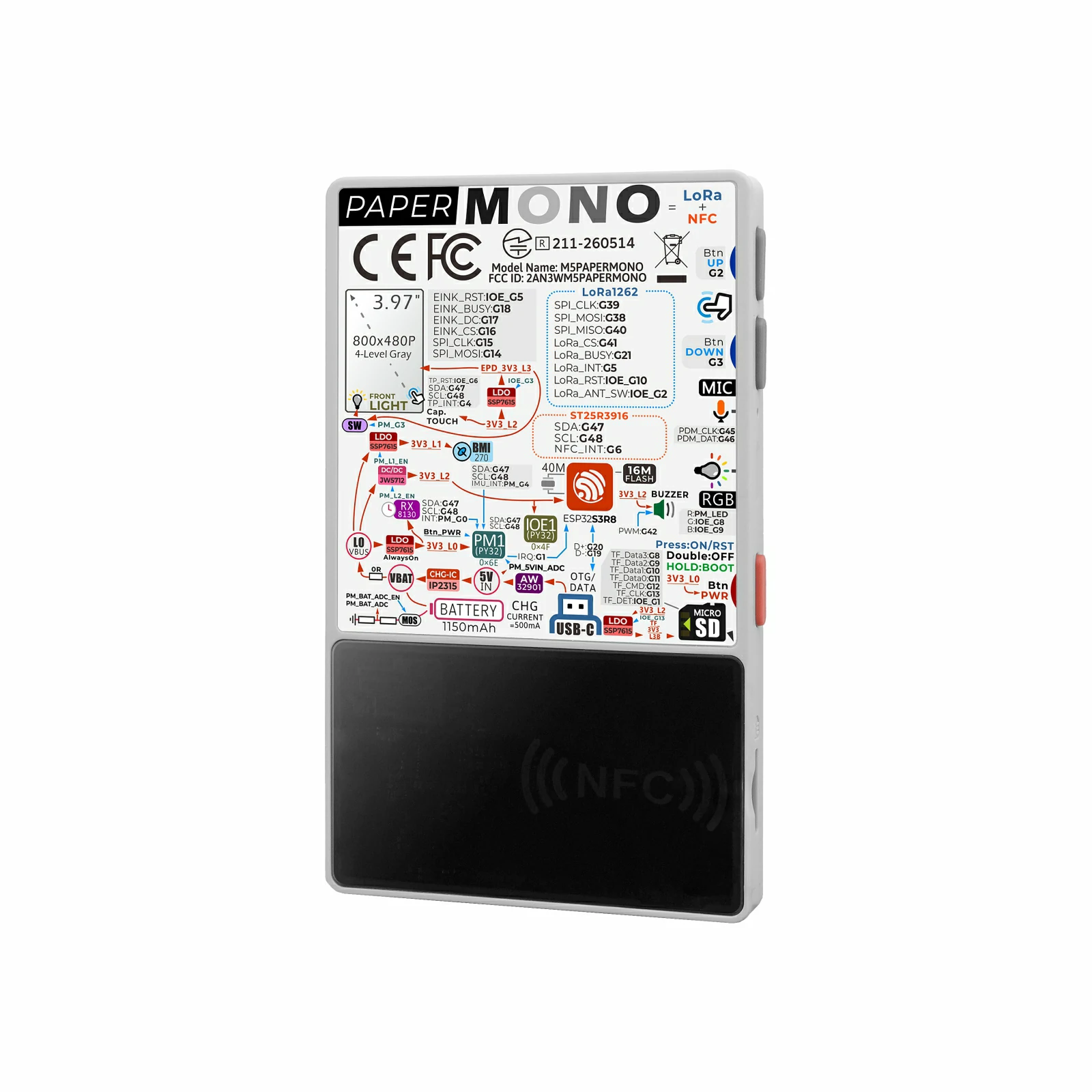
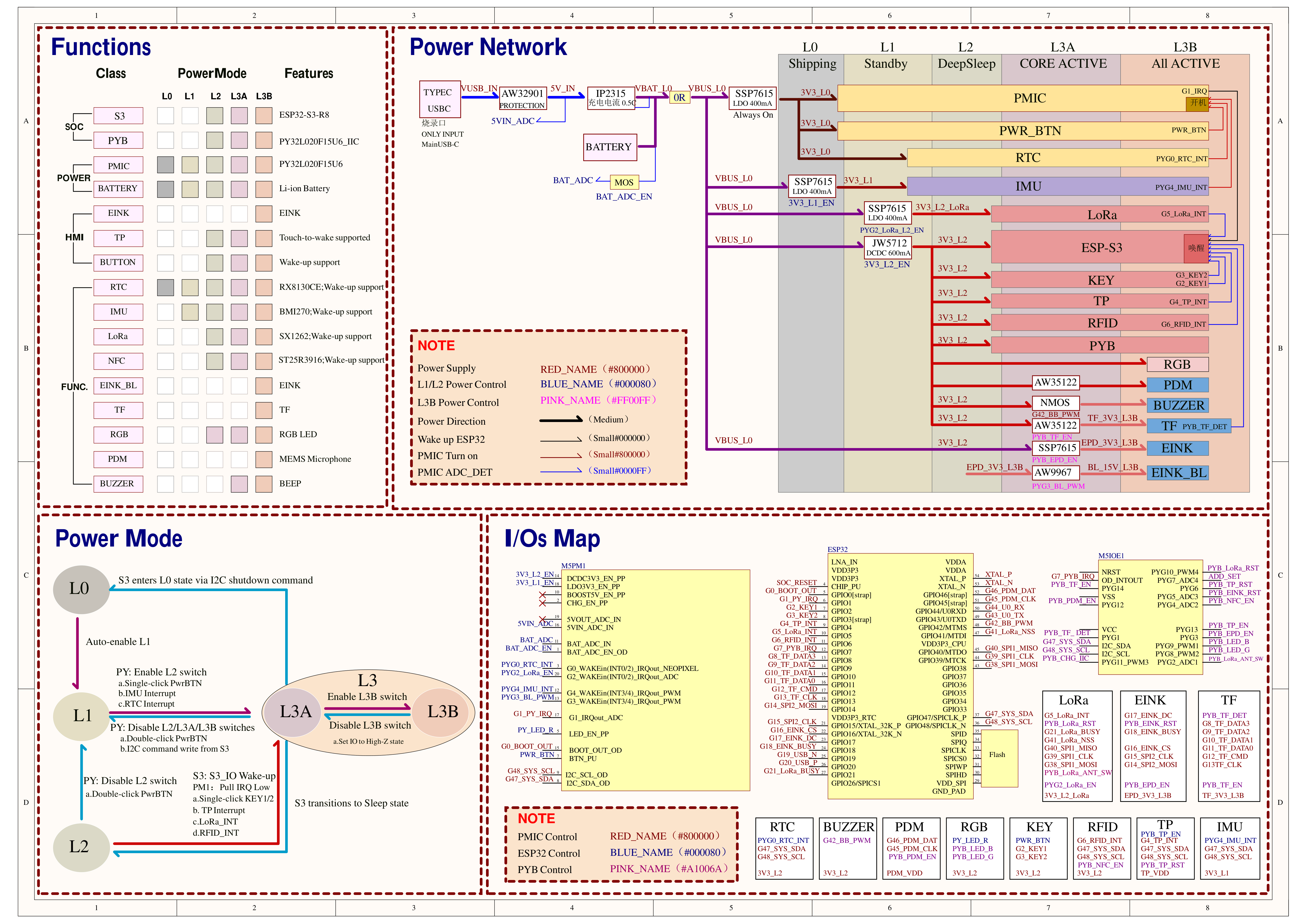
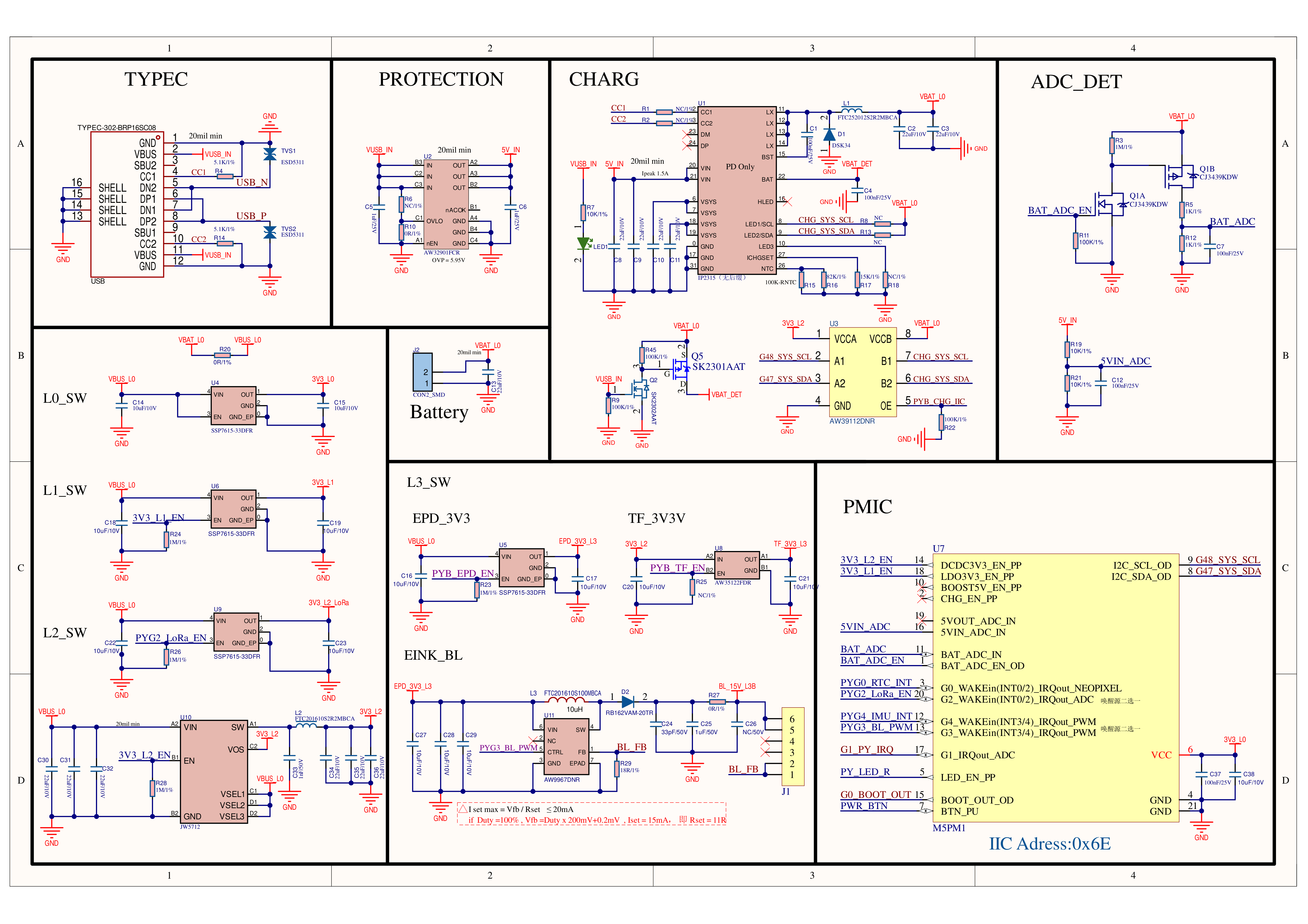
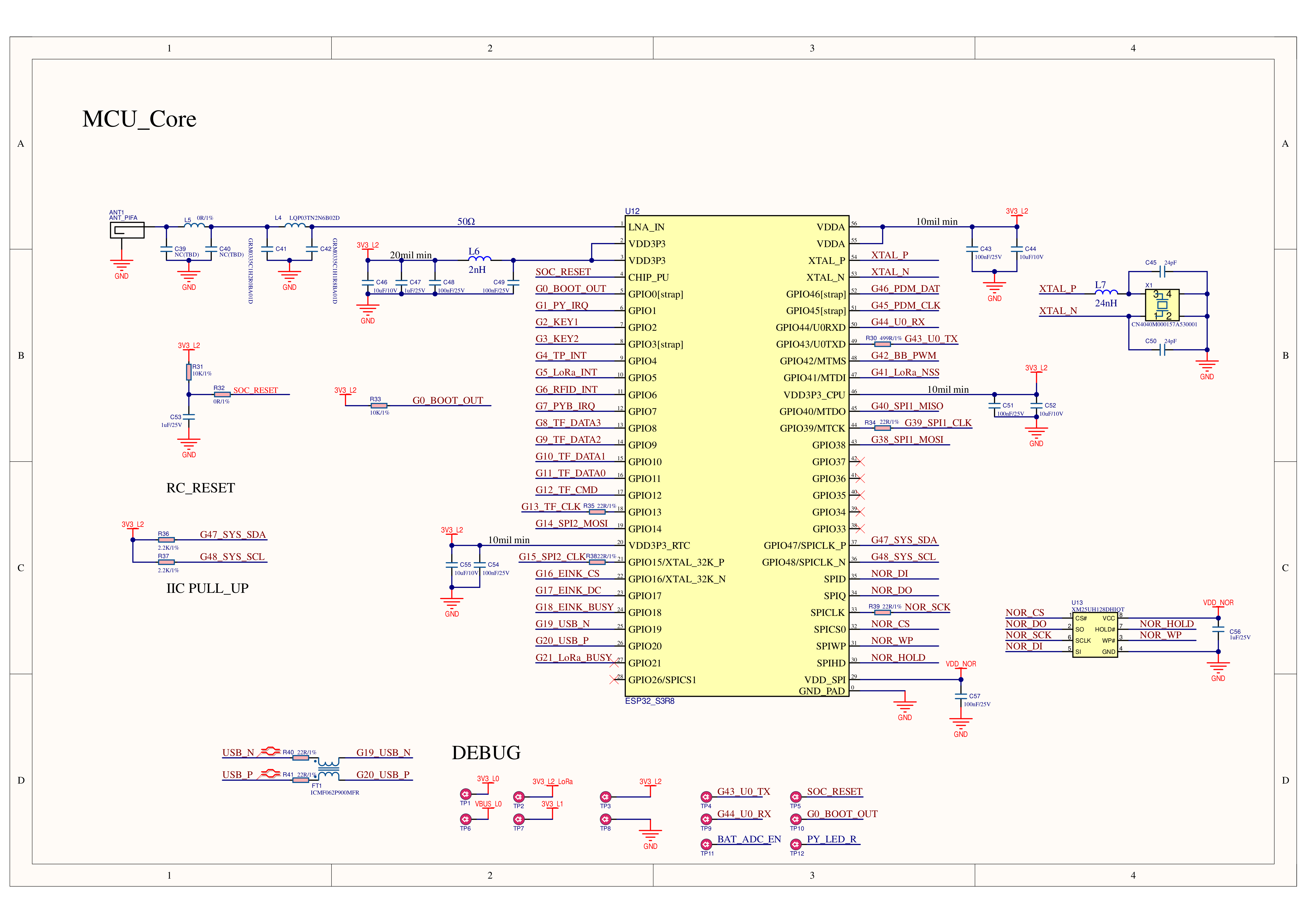
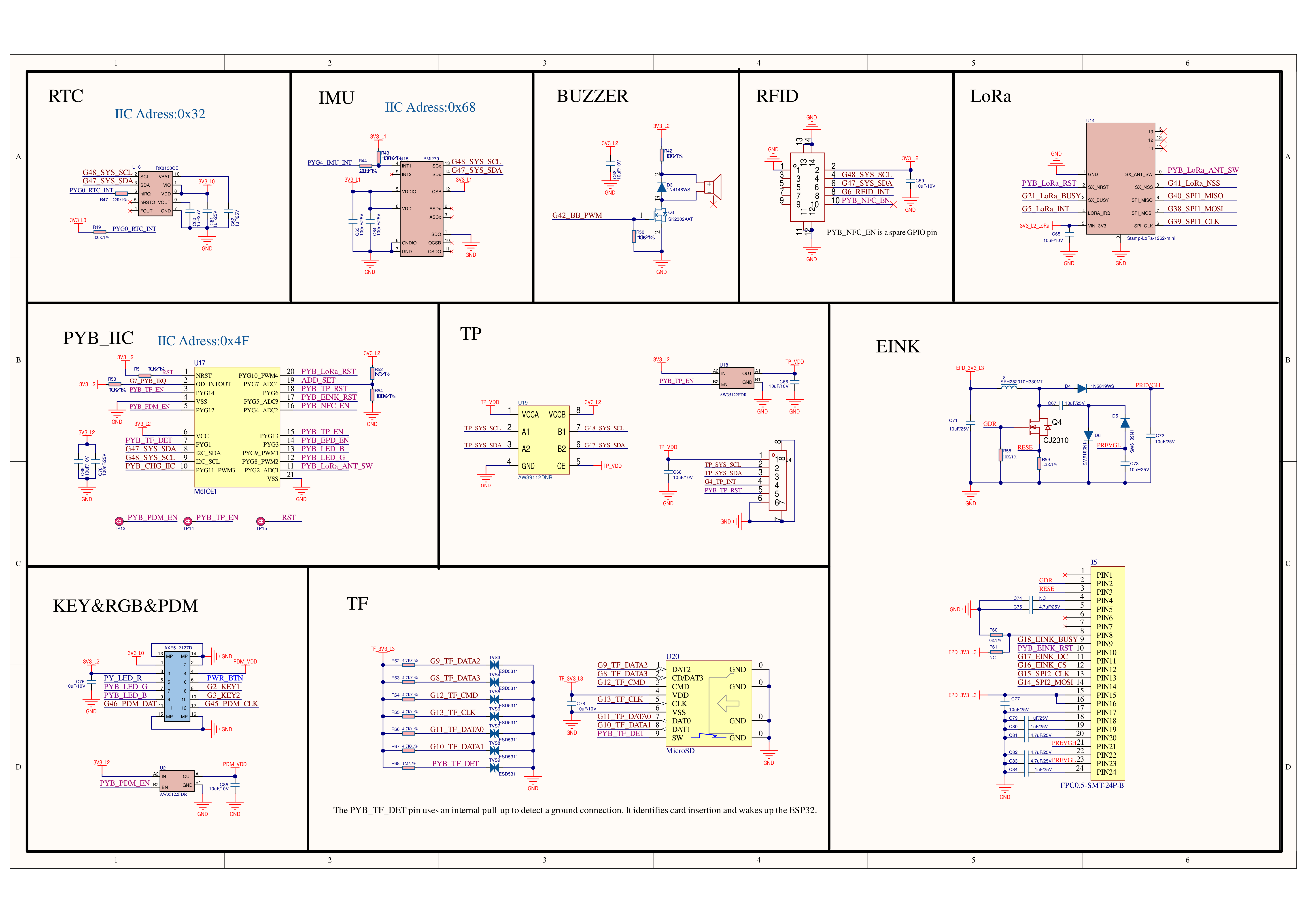
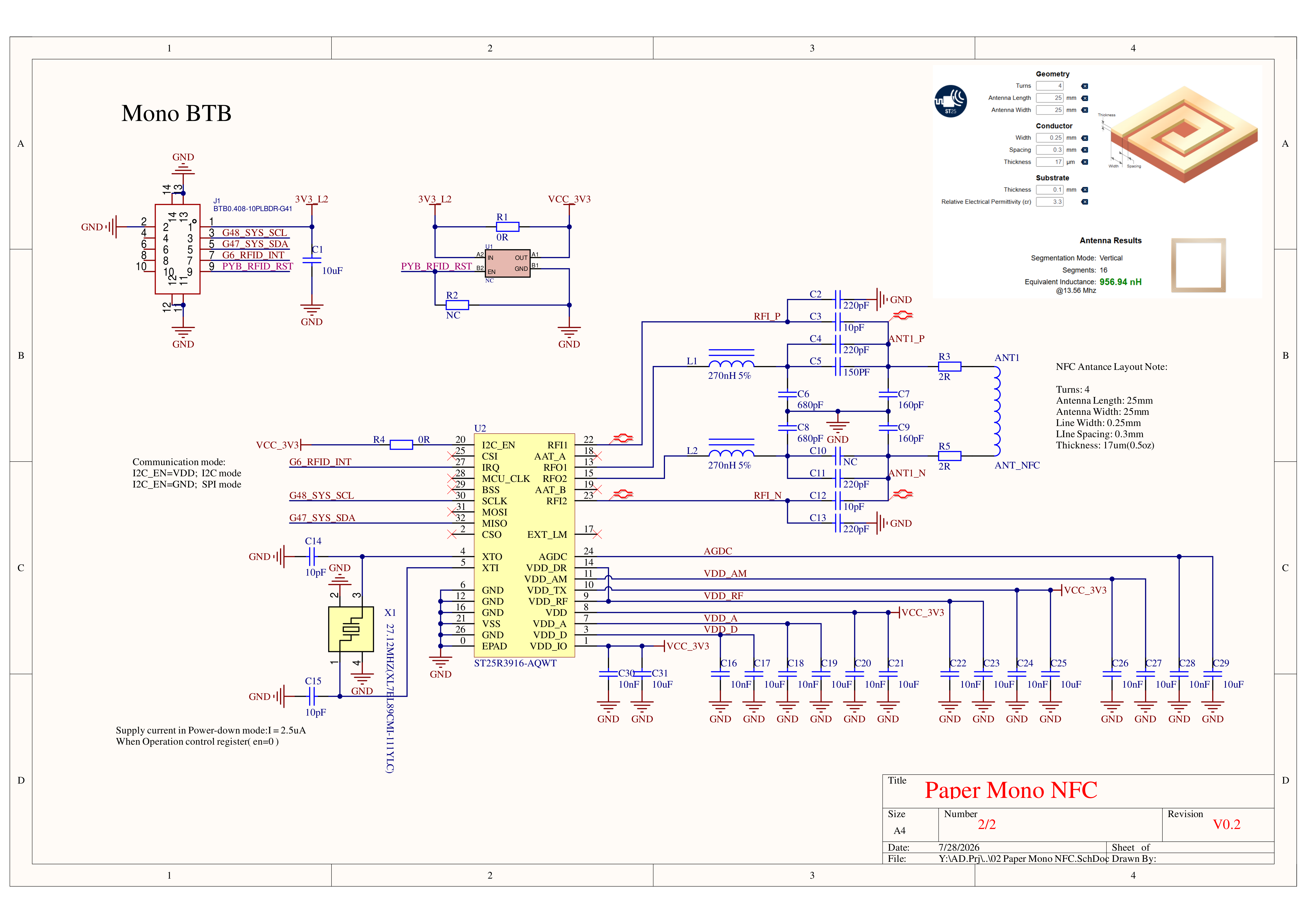
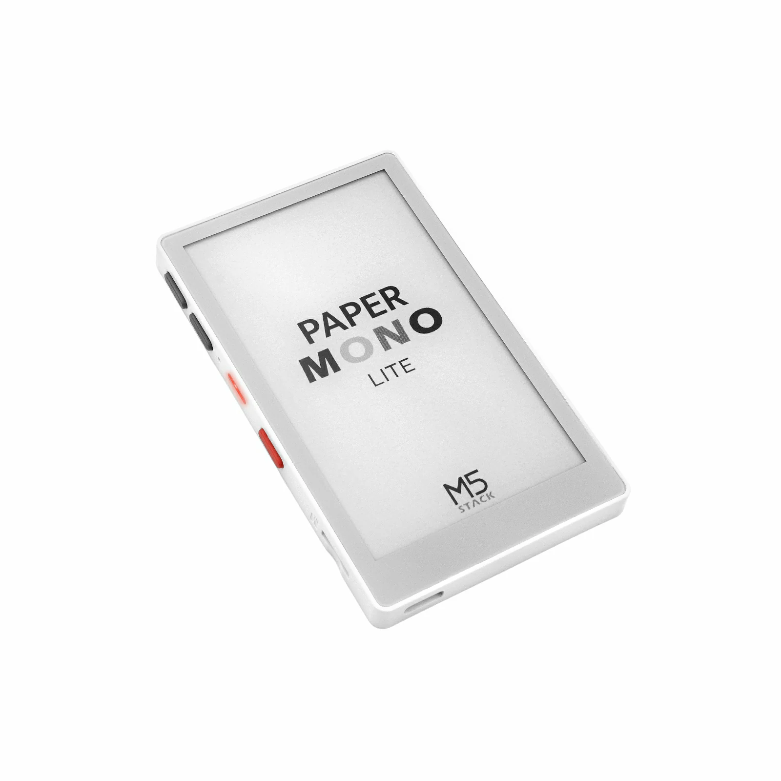
PaperMono is an e-paper development board built around low-power display, near-field identification, and long-range communication capabilities. It features a touch-enabled 3.97-inch 4-level grayscale monochrome e-paper display, driven by SSD1677 with a resolution of 480 x 800, and integrates an FT6336G touch controller and a frontlight system for a more comfortable reading and interaction experience in low-light environments. The core adopts an ESP32-S3R8, paired with 16MB Flash, 8MB PSRAM, and 2.4 GHz Wi-Fi, along with an onboard buzzer, PDM microphone (LMD4737T261-AC02), RGB LED, BMI270 6-axis IMU, M5IOE1 IO expander, microSD card slot, and RX8130CE real-time clock. The NFC section is based on the ST25R3916, supporting ISO14443A, ISO14443B, FeliCa™, and ISO15693; LoRa communication adopts the SX1262 (Stamp LoRa-1262) solution with a built-in FPC antenna, supporting the 868MHz ~ 923MHz band. Combined with the M5PM1 multi-level power management system and a 1150mAh battery, it meets the requirements of low-power IoT and embedded applications such as e-readers, e-paper signage, access control terminals, identity authentication, and intelligent transportation.
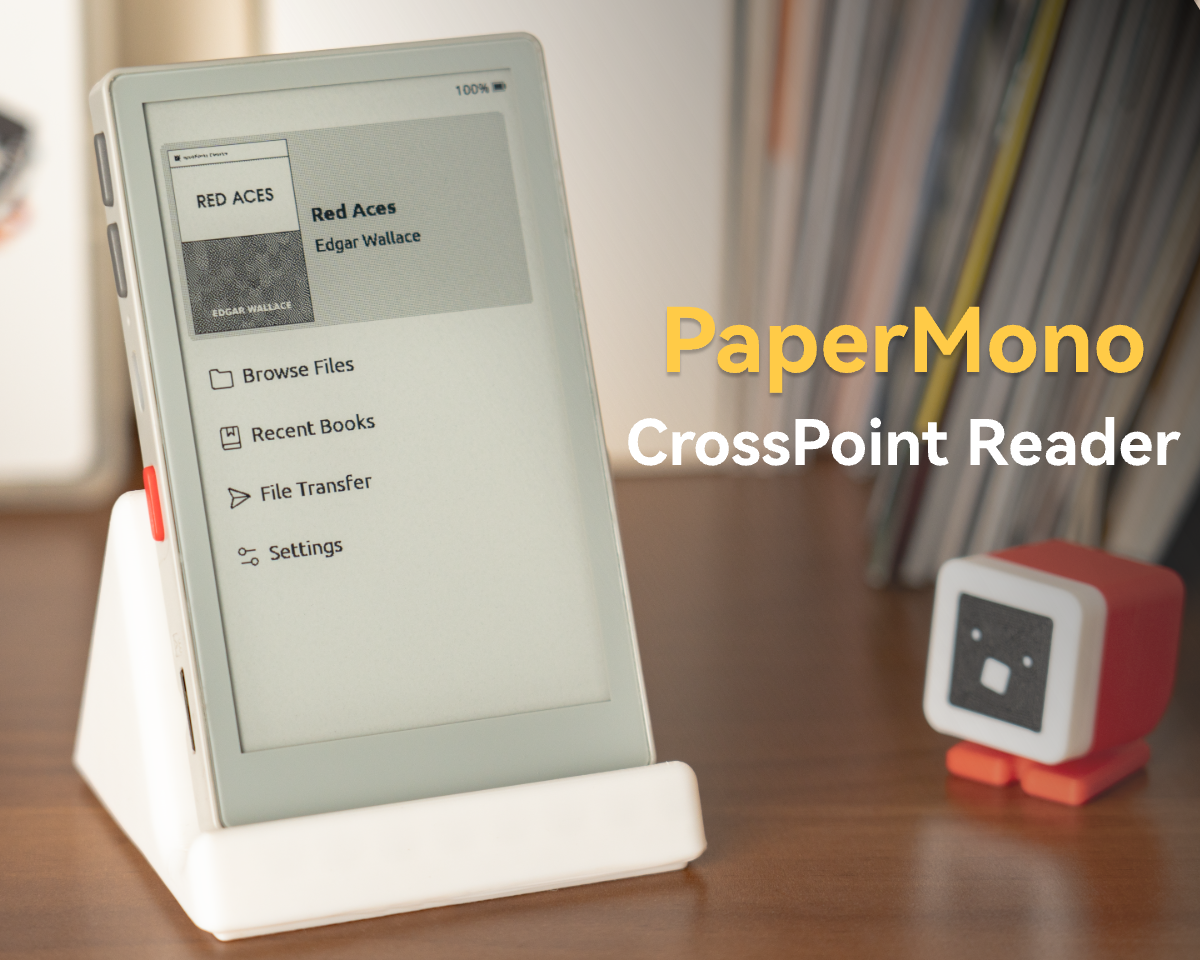
Click here to download the PaperMono CrossPoint E-Reader firmware.
Note
E-Paper Usage Precautions
Avoid direct sunlight/prolonged sun exposure during use; high temperatures or strong UV can damage the panel.
After approximately 10 partial fast refreshes in software, it is recommended to perform one full-screen refresh to clear the screen and avoid severe accumulated ghosting.
The screen has built-in OTP waveforms that can be called directly. When using custom external waveforms, pay attention to DC balance; otherwise, irreversible damage may be caused to the panel.
Avoid uninterrupted continuous partial fast refreshes, to prevent long-term DC imbalance from causing irreversible damage to the panel.
Touch Active Area
PaperMono Touch Active Area
The touch IC firmware internally shrinks the touch boundary. The effective touch coordinate range is limited to: X-axis: 5 ~ 475 (total width 480px), Y-axis: 5 ~ 795 (total height 800px).
Features
ESP32-S3R8 Core Controller
16MB Flash
8MB PSRAM
2.4 GHz Wi-Fi
3.97-inch 4-level grayscale monochrome e-paper display with touch
2x user buttons + 1x power button (ON / OFF / RESET / BOOT)
Product Size
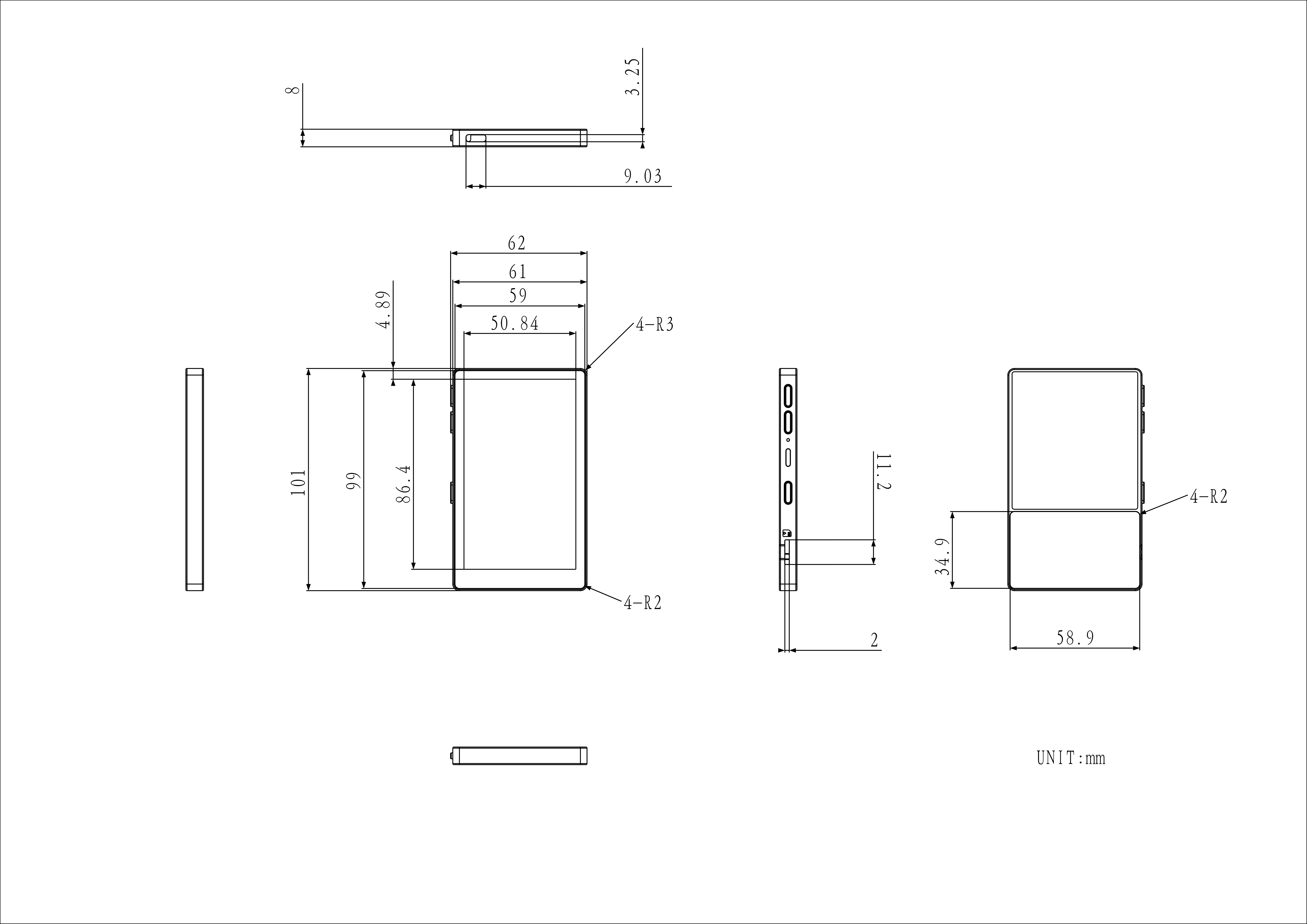
62.0 x 101.0 x 8.0mm
Product Weight
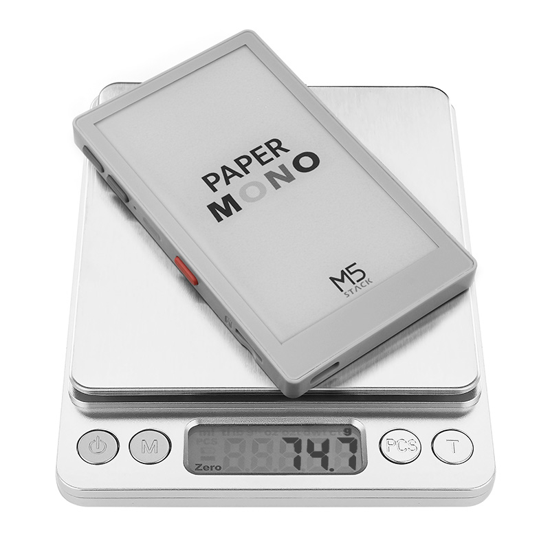
74.7g
Package Size
113.2 x 69.6 x 21.0mm
Gross Weight
91.3g
Learn
Power On/Off
Power on / Reset: press the power button once briefly
Power off: press the power button twice in succession
Download Mode
Press and hold the power button (about 2 seconds) until the red LED blinks, then release. The device enters download mode and is ready for flashing.
M5GFX LUT Refresh Speed
The following data is the laboratory test result of PaperMono under different M5GFX refresh modes. The actual refresh time may vary depending on the display content and operating environment, and is provided for reference only.
The e-paper reset is controlled via PYG5_ADC3 of the M5IOE1, and PYG3 controls the 3.3V power supply of the e-paper; the frontlight brightness is controlled via PYG3_BL_PWM of the M5PM1.
Touch
ESP32-S3R8
G47_SYS_SDA
G48_SYS_SCL
G4_TP_INT
FT6336G(0x38)
SDA
SCL
INT
M5IOE1
PYG6
PYG13
FT6336G
TP_RST
TP_VDD_EN
microSD
ESP32-S3R8
G12
G13
G11
G10
G9
G8
microSD
CMD
CLK
DAT0
DAT1
DAT2
DAT3
M5IOE1
PYG14
PYG1
microSD
TF_EN
TF_DET
TF_DET is pulled up by the microSD power domain. When the card slot switch is closed, the detection pin is pulled low to identify microSD card insertion.
HMI
ESP32-S3R8
G47_SYS_SDA
G48_SYS_SCL
G2_KEY1
G3_KEY2
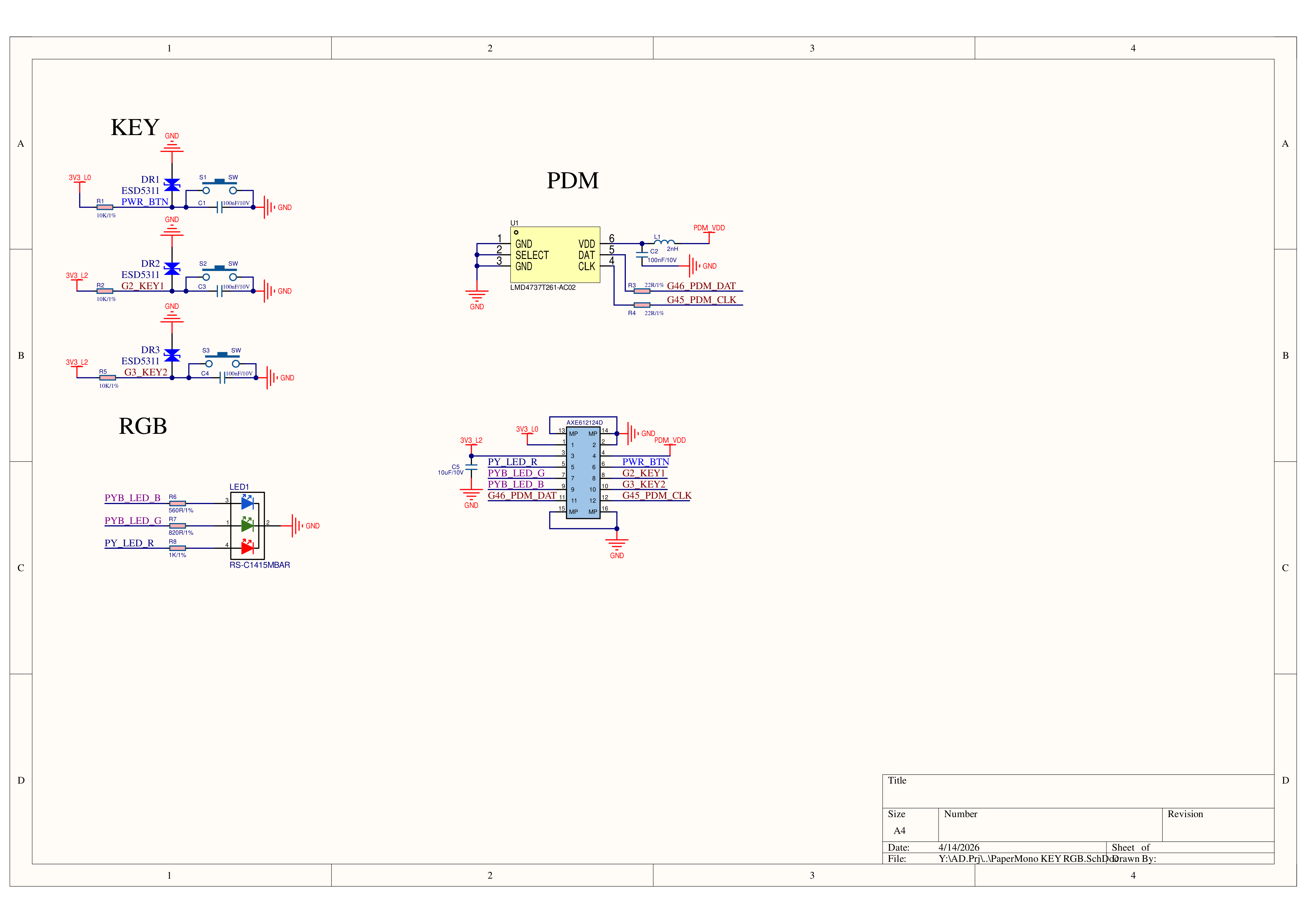
RTC - RX8130CE(0x32)
SDA
SCL
IMU - BMI270(0x68)
SDA
SCL
KEY
KEY1
KEY2
M5PM1
G0_WAKEin
G4_WAKEin
LED_EN_PP
HMI
RTC_INT
IMU_INT
LED_R
PYG0_RTC_INT and PYG4_IMU_INT are connected to the M5PM1 and can serve as low-power wake-up sources.
M5IOE1
PYG8_PWM2
PYG9_PWM1
HMI
LED_G
LED_B
The RGB LED indicator on the side of the PaperMono body consists of three color LED dies, with the red LED connected to LED_EN_PP of the M5PM1. After the device is powered on, it will light up according to the M5PM1 default behavior. Since LED_EN_PP does not support PWM output mode configuration, the adjustable colors of this indicator will be limited.
KEY
ESP32-S3R8
G2
G3
KEY
USER_KEY1 (Button A)
USER_KEY2 (Button B)
Audio
ESP32-S3R8
G46_PDM_DAT
G45_PDM_CLK
G42_BB_PWM
PDM MIC
DAT
CLK
BUZZER
BB_PWM
M5IOE1
PYG12
PDM
PDM_VDD_EN
M5PM1
ESP32-S3R8
G47_SYS_SDA
G48_SYS_SCL
G1_PY_IRQ
G0_BOOT_OUT
M5PM1(0x6E)
SDA
SCL
IRQ
BOOT_OUT
M5IOE1
ESP32-S3R8
G47_SYS_SDA
G48_SYS_SCL
G7
M5IOE1(0x4F)
SDA
SCL
PYB_IRQ
M5IOE1
PYG11_PWM3
Charger - IP2315(0x75)
PYB_CHG_IIC
Note
The I2C operating mode of the charging chip IP2315 depends on the I2C pins being pulled up to VBAT voltage. Connecting the device to USB triggers mode detection; if the VBAT voltage is too low, the IP2315 may not initialize into I2C mode properly, which can interfere with other devices on the same I2C bus. M5IOE1 controls the connection between the IP2315 and the system I2C bus via PYG11_PWM3: during device operation, do not keep the IP2315 mounted on the I2C bus for extended periods; disconnect it promptly after communication to avoid reducing bus communication stability. If an I2C bus communication anomaly occurs, you can reset the device by briefly pressing the power button to restore normal bus operation.
1. The e-paper driver waveforms for PaperMono in the M5GFX library are currently unstable. It is recommended to prioritize the e-paper manufacturer's OTP example below for refresh configuration to achieve better panel life and refresh stability. 2. Software recommendation: After approximately 10 partial fast refreshes, perform one full-screen refresh to clear the screen and prevent ghosting from accumulating. 3. After prolonged repeated refreshing, black deposited pixels may appear on the panel due to the physical characteristics of the ink particles. Leave the panel idle for a while, then perform one full-screen refresh to restore it.