

Arduino Quick Start
2. Devices & Examples
3. M5Unified
4. M5GFX
5. Extensions
Unit
Module
Atomic
Tab5
IoT
Accessories
PaperMono M5PM1 & M5IOE1 Power Management
1. Multi-Level Power Switching Design
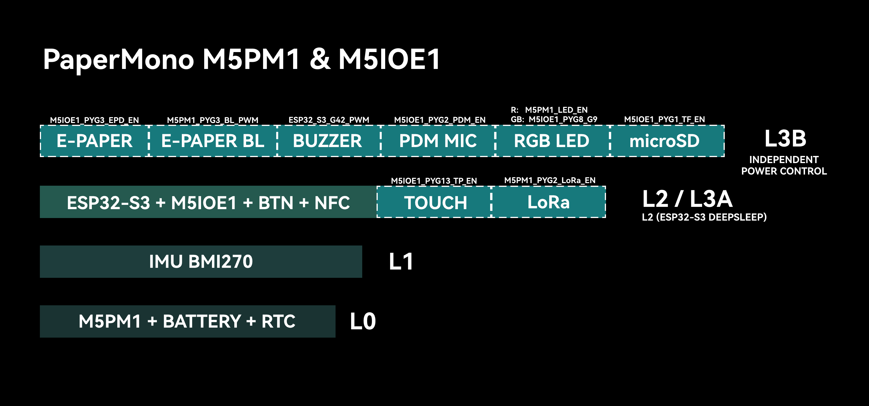
PaperMono integrates the M5PM1 and M5IOE1 with hardware circuitry to implement multi-level power switching. Each power level controls the supply to specific peripherals and interfaces. Users can enable different power levels as required and turn off unused peripherals to reduce overall power consumption.
M5PM1 / M5IOE1 Driver Libraries
The M5PM1 and M5IOE1 driver libraries provide a convenient way to configure M5PM1 and M5IOE1 pin functions for low-power wakeup and peripheral power switching.
L0
At this power level, the battery continues to supply the M5PM1 and RTC. This level remains active as long as the battery is not depleted. The M5PM1 supports basic push-button power on/off operation and wakeup through an RTC interrupt.
L1
At this power level, power to the IMU is newly enabled. This level uses the M5PM1 3V3_L1_EN power switch, which can be controlled through the following API.
pm1.setLdoEnable(true); // L1 ON
pm1.setLdoEnable(false); // L1 OFFThe IMU INT1 interrupt pin is also connected to PYG4 on the M5PM1. By configuring the relevant registers, power to the IMU can be retained while the M5PM1 enters sleep. Rotating the device then triggers the active-high IMU interrupt to wake the M5PM1. Use the following API to retain IMU (L1) power.
pm1.setLdoEnable(true);
pm1.ldoSetPowerHold(true);
pm1.setLedEnLevel(true);
pm1.shutdown();L2 \ L3A
At this power level, power or control is newly enabled for the ESP32-S3, LoRa module, NFC/RFID module, M5IOE1 I/O expander, user-button pull-up, display touch interrupt, buzzer, and red channel of the RGB LED. This level uses the M5PM1 3V3_L2_EN power switch, which can be controlled through the following API.
pm1.setDcdcEnable(true); // L2 ON
pm1.setDcdcEnable(false); // L2 OFFWhen the ESP32-S3 is sleeping, the power system is at level L2. When the ESP32-S3 is operating, it is at level L3A. The ESP32-S3 can instruct the M5PM1 to enter sleep and turn off its own power supply (L2 -> L1/L0).
L3B
Level L3B controls the power or related configuration for higher-consumption peripherals such as the display, touch controller, microSD detection, PDM microphone, and RGB LED. This level is controlled through the M5IOE1 I/O expander, allowing some peripherals at this level to be controlled independently.
| M5IOE1 | PYG1 | PYG2 | PYG3 | PYG4_ADC2 | PYG5 | PYG6 | PYG8 | PYG9 | PYG10 | PYG12 | PYG13 | PYG14 |
|---|---|---|---|---|---|---|---|---|---|---|---|---|
| microSD | PYB_TF_DET | PYB_TF_EN | ||||||||||
| LoRa | PYB_LoRa_ANT_SW | PYB_LoRa_RST | ||||||||||
| E-Paper | PYB_EPD_EN | PYB_EINK_RST | ||||||||||
| NFC / RFID | PYB_NFC_EN | |||||||||||
| Touch | PYB_TP_RST | PYB_TP_EN | ||||||||||
| RGB LED | PYB_LED_G | PYB_LED_B | ||||||||||
| PDM | PYB_PDM_EN |
- PYB_TF_DET: microSD detection
- PYB_TF_EN: microSD power
- PYB_LoRa_ANT_SW: LoRa antenna switch
- PYB_LoRa_RST: LoRa reset
- PYB_EPD_EN: E-Paper power
- PYB_EINK_RST: E-Paper reset
- PYB_NFC_EN: NFC / RFID enable and reset
- PYB_LED_G: RGB LED green-channel control
- PYB_LED_B: RGB LED blue-channel control
- PYB_PDM_EN: PDM power
- PYB_TP_EN: Touch power
- PYB_TP_RST: Touch reset
2. M5PM1 Sleep
Manual Sleep
The M5PM1 can be placed into sleep manually through software to reduce overall power consumption. By default, entering sleep directly returns the power system to level L0, where only the M5PM1 remains powered.
pm1.shutdown();In special use cases, such as IMU wakeup or ESP32-S3 SoC sleep, the M5PM1 can enter sleep while retaining power to selected peripheral levels for wakeup sources or state retention.
For these applications, configure the power-switch pin state for the required level and enable state retention before the M5PM1 enters sleep mode.
I2C Idle Sleep
The M5PM1 can be configured to enter sleep automatically when I2C communication is idle, reducing overall power consumption. After it enters sleep, the first communication from the ESP32-S3 is used to wake the M5PM1 and therefore fails. Valid communication completes on the next attempt after wakeup.
m5pm1_err_t setI2cSleepTime(uint8_t seconds);3. M5PM1 Timer
The M5PM1 timer can be configured to perform a corresponding action when the countdown ends, such as powering on, powering off, or resetting the device.
m5pm1_err_t timerSet(uint32_t seconds, m5pm1_tim_action_t action);typedef enum {
M5PM1_TIM_ACTION_STOP = 0b000, // Stop, no action
M5PM1_TIM_ACTION_FLAG = 0b001, // Set flag only
M5PM1_TIM_ACTION_REBOOT = 0b010, // System reboot
M5PM1_TIM_ACTION_POWERON = 0b011, // Power on
M5PM1_TIM_ACTION_POWEROFF = 0b100 // Power off
} m5pm1_tim_action_t;Timed Power-On / Power-Off Example
Example description: After the device powers on, click button A to configure a 10s timer that triggers a power-on sequence. Click button B to configure the timer to power off the M5PM1 after 10s. The device can then be powered on again by clicking the power button.
#include <M5Unified.h>
#include <M5PM1.h>
M5PM1 pm1;
void setup()
{
auto cfg = M5.config();
cfg.clear_display = false;
M5.begin(cfg);
Serial.begin(115200);
const m5pm1_err_t err = pm1.begin(&M5.In_I2C, M5PM1_DEFAULT_ADDR, M5PM1_I2C_FREQ_100K);
if (err != M5PM1_OK) {
Serial.printf("M5PM1 init failed: %d\n", err);
while (true) {
delay(1000);
}
}
M5.Display.setEpdMode(epd_mode_t::epd_fast);
M5.Display.setTextDatum(middle_center);
M5.Display.setFont(&fonts::FreeSansBold18pt7b);
M5.Display.drawString("BtnA: power on after 10s", M5.Display.width() / 2, 280);
M5.Display.drawString("BtnB: power off after 10s", M5.Display.width() / 2, 340);
}
void loop(void)
{
M5.update();
if (M5.BtnA.wasPressed()) {
M5.Display.clear();
M5.Display.setCursor(40, 80);
M5.Display.println("Shutdown");
M5.Display.println(" After 10s");
M5.Display.println(" Power ON");
delay(500);
pm1.timerSet(10, M5PM1_TIM_ACTION_POWERON);
pm1.shutdown();
}
if (M5.BtnB.wasPressed()) {
M5.Display.clear();
M5.Display.setCursor(40, 80);
M5.Display.println(" After 10s");
M5.Display.println(" Power OFF");
delay(500);
pm1.timerSet(10, M5PM1_TIM_ACTION_POWEROFF);
}
}After initializing the M5PM1, pressing button A schedules a power-on action for 10 seconds later and immediately calls shutdown(); the device powers on again when the timer expires. Pressing button B schedules a power-off action for 10 seconds later. The device continues running until the countdown ends and can be powered on again with the power button after shutdown.
4. IMU Wakeup
BMI270 Driver Library
Waking the M5PM1 with the IMU
When power switches to L1 mode, only the IMU, RTC, and M5PM1 remain powered. After IMU wakeup is configured, the M5PM1 also enters sleep while retaining the L1 power output (3V3_L1_EN) to keep the IMU operating.
Rotating or moving the device triggers the IMU wakeup signal, waking and restarting the M5PM1.
After the M5PM1 wakes, it repeats the L0, L1, and L2 power-on sequence. The ESP32-S3 then runs initialization again.
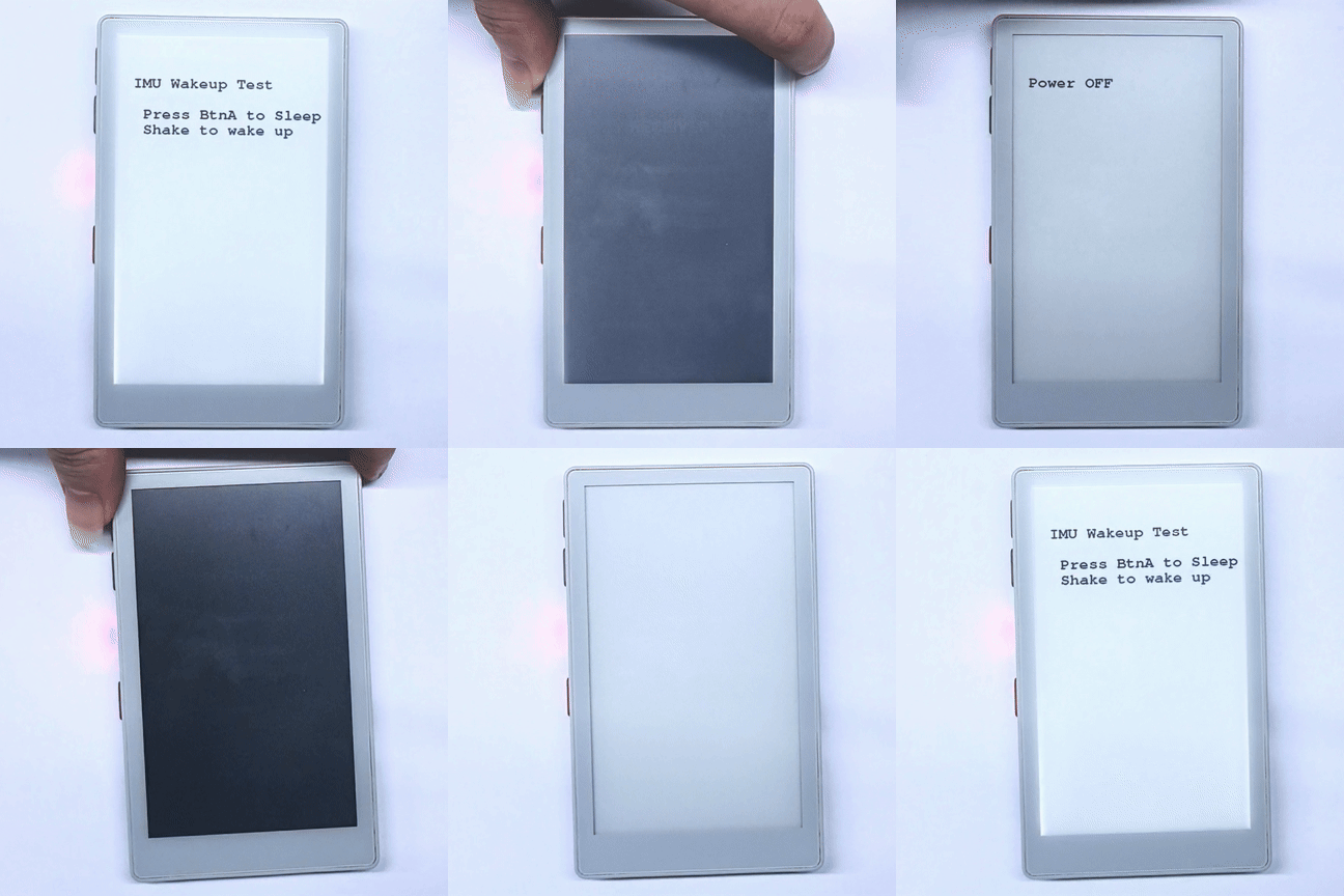
Example description: After the device powers on, click button A to configure the IMU interrupt mode and M5PM1 L1 power retention, after which the M5PM1 enters sleep. Rotating or moving the device then wakes the M5PM1 and powers the ESP32-S3 on again.
#include <M5Unified.h>
#include <M5PM1.h>
#include <Wire.h>
#include "SparkFun_BMI270_Arduino_Library.h"
BMI270 imu;
M5PM1 pm1;
void setup(void)
{
auto cfg = M5.config();
cfg.clear_display = false;
M5.begin(cfg);
Serial.begin(115200);
Wire1.setPins(M5.getPin(m5::pin_name_t::in_i2c_sda), M5.getPin(m5::pin_name_t::in_i2c_scl));
// Initialize PM1
m5pm1_err_t err = pm1.begin(&M5.In_I2C, M5PM1_DEFAULT_ADDR, M5PM1_I2C_FREQ_100K);
if (err == M5PM1_OK) {
Serial.println("PM1 initialization successful");
pm1.gpioSetWakeEnable(M5PM1_GPIO_NUM_4, true);
pm1.gpioSetWakeEdge(M5PM1_GPIO_NUM_4, M5PM1_GPIO_WAKE_FALLING); // Falling edge
} else {
Serial.printf("PM1 initialization failed, error code: %d\n", err);
}
pm1.setSingleResetDisable(false);
// Check if sensor is connected and initialize
while(imu.beginI2C(BMI2_I2C_PRIM_ADDR, Wire1) != BMI2_OK)
{
Serial.println("Error: BMI270 not connected, check wiring and I2C address!");
delay(1000);
}
imu.disableFeature(BMI2_ANY_MOTION);
Serial.println("BMI270 initialization successful");
M5.Display.setEpdMode(epd_mode_t::epd_fast);
M5.Display.setFont(&fonts::FreeMonoBold18pt7b);
M5.Display.clear();
M5.Display.setCursor(40, 100);
M5.Display.printf("IMU Wakeup Test\n\n");
M5.Display.println(" Press BtnA to Sleep");
M5.Display.println(" Shake to wake up");
}
void loop(void)
{
M5.update();
if (M5.BtnA.wasPressed()) {
int8_t ret = imu.enableFeature(BMI2_ANY_MOTION);
// Optional
// bmi2_sens_config config;
// config.type = BMI2_ANY_MOTION;
// config.cfg.any_motion.threshold = 0xA0;// 1LSB equals to 0.48mg. Default is 83mg. Lower is more sensitive
// config.cfg.any_motion.duration = 0x0A; // 1LSB equals 20ms. Default is 100ms.
// ret |= imu.setConfig(config);
//
bmi2_int_pin_config intPinConfig;
intPinConfig.pin_type = BMI2_INT1;
intPinConfig.int_latch = BMI2_INT_NON_LATCH;
intPinConfig.pin_cfg[0].lvl = BMI2_INT_ACTIVE_LOW;
intPinConfig.pin_cfg[0].od = BMI2_INT_PUSH_PULL;
intPinConfig.pin_cfg[0].output_en = BMI2_INT_OUTPUT_ENABLE;
intPinConfig.pin_cfg[0].input_en = BMI2_INT_INPUT_DISABLE;
ret |= imu.setInterruptPinConfig(intPinConfig);
ret |= imu.mapInterruptToPin(BMI2_ANY_MOTION_INT, BMI2_INT1);
if (!ret){
Serial.println("BMI270 AnyMotionInterrupt enabled successfully");
} else {
Serial.println("Failed to enable BMI270 AnyMotionInterrupt");
}
M5.Display.clear();
M5.Display.setCursor(40, 100);
M5.Display.println("Power OFF");
delay(1000);
// Shutdown
pm1.setLdoEnable(true);
pm1.ldoSetPowerHold(true);
pm1.setLedEnLevel(true);
pm1.shutdown();
}
} After button A is pressed, the program enables BMI270 any-motion detection, maps the interrupt to active-low INT1, retains M5PM1 L1 power, and powers off the device. When rotating or moving the device triggers the interrupt, the M5PM1 restores power to each level, and the ESP32-S3 powers on and starts running from setup().
Waking the ESP32-S3 with the IMU
The M5PM1 PYG1_IRQ pin is connected to ESP32-S3 G1 in the circuit, allowing the ESP32-S3 to be woken through a chained wakeup signal. The procedure is as follows:
- Configure M5PM1 PYG4 as an input. This pin is connected to the IMU INT1 output signal.
- Configure M5PM1 PYG4_IRQ as the IRQ output signal. When the state of PYG4 changes because the IMU generates an interrupt, the PYG1_IRQ pin outputs an interrupt signal.
- Configure the ESP32-S3 to enter sleep and set G1 as its wakeup pin.
- Rotate or move the device: trigger the IMU wakeup signal -> trigger M5PM1 PYG1_IRQ -> wake the ESP32-S3.
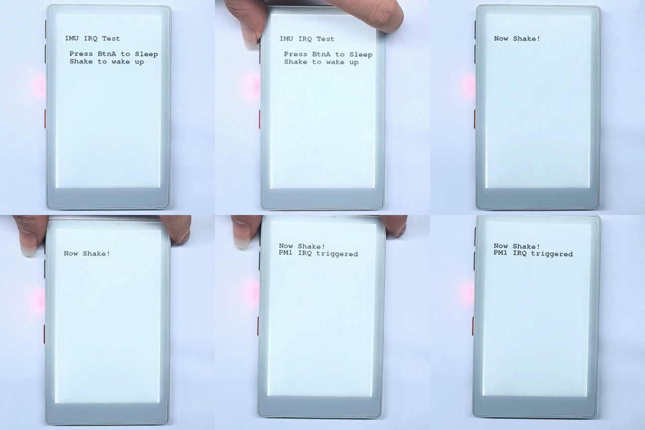
Example description: After the device powers on, click button A to configure the IMU interrupt mode. Rotating or moving the device triggers the GPIO interrupt handler. Click button A again to clear the M5PM1 IRQ flag and repeat the test.
#include <M5Unified.h>
#include <M5PM1.h>
#include <Wire.h>
#include "SparkFun_BMI270_Arduino_Library.h"
#include "driver/rtc_io.h"

BMI270 imu;
M5PM1 pm1;

void setup(void)
{
    auto cfg = M5.config();
    cfg.clear_display = false;
    M5.begin(cfg);
    Serial.begin(115200);

    Wire1.setPins(M5.getPin(m5::pin_name_t::in_i2c_sda), M5.getPin(m5::pin_name_t::in_i2c_scl));

    // Initialize PM1
    m5pm1_err_t err = pm1.begin(&M5.In_I2C, M5PM1_DEFAULT_ADDR, M5PM1_I2C_FREQ_100K);

    if (err == M5PM1_OK) {
        Serial.println("PM1 initialization successful");
        pm1.irqClearGpioAll();
        pm1.irqClearSysAll();
        pm1.irqClearBtnAll();

        pm1.irqSetGpioMaskAll(M5PM1_IRQ_MASK_ENABLE);
        pm1.irqSetSysMaskAll(M5PM1_IRQ_MASK_ENABLE);
        pm1.irqSetBtnMaskAll(M5PM1_IRQ_MASK_ENABLE);

        pm1.irqSetGpioMask(M5PM1_IRQ_GPIO4, M5PM1_IRQ_MASK_DISABLE);
        pm1.gpioSetMode(M5PM1_GPIO_NUM_4, M5PM1_GPIO_MODE_INPUT);
        pm1.gpioSetPull(M5PM1_GPIO_NUM_4, M5PM1_GPIO_PULL_UP);

        pm1.gpioSetMode(M5PM1_GPIO_NUM_1, M5PM1_GPIO_MODE_OUTPUT);
        pm1.gpioSetDrive(M5PM1_GPIO_NUM_1, M5PM1_GPIO_DRIVE_PUSHPULL);
        pm1.gpioSetFunc(M5PM1_GPIO_NUM_1, M5PM1_GPIO_FUNC_IRQ);
    } else {
        Serial.printf("PM1 initialization failed, error code: %d\n", err);
    }
    pm1.setSingleResetDisable(false);

    // Check if sensor is connected and initialize
    while(imu.beginI2C(BMI2_I2C_PRIM_ADDR, Wire1) != BMI2_OK)
    {
        Serial.println("Error: BMI270 not connected, check wiring and I2C address!");
        delay(1000);
    }
    imu.disableFeature(BMI2_ANY_MOTION);
    Serial.println("BMI270 initialization successful");

    M5.Display.setEpdMode(epd_mode_t::epd_fast);
    M5.Display.setFont(&fonts::FreeMonoBold18pt7b);
    M5.Display.clear();
    M5.Display.setCursor(40, 100);
    M5.Display.printf("IMU IRQ Test\n\n");
    M5.Display.println("   Press BtnA to Sleep");
    M5.Display.println("   Shake to wake up");
}

volatile bool pm1IrqTriggered = false;

void ARDUINO_ISR_ATTR pm1_irq_handler()
{
    pm1IrqTriggered = true;
}

void loop(void)
{
    M5.update();

    if (pm1IrqTriggered) {
        pm1IrqTriggered = false;

        Serial.println("PM1 IRQ triggered");

        uint16_t status = 0;
        imu.getInterruptStatus(&status);
        Serial.printf("BMI270 interrupt status: 0x%04X\n", status);

        M5.Display.setCursor(40, 130);
        M5.Display.println("PM1 IRQ triggered");
    }

    if (M5.BtnA.wasPressed()) {
        pm1.irqClearGpioAll();
        pm1.irqClearSysAll();
        pm1.irqClearBtnAll();
        int8_t ret = imu.enableFeature(BMI2_ANY_MOTION);
        // Optional
        // bmi2_sens_config config;
        // config.type = BMI2_ANY_MOTION;
        // ret |= imu.getConfig(&config);
        // config.cfg.any_motion.threshold = 0xE0;// 1LSB equals to 0.48mg. Default is 83mg. Lower is more sensitive
        // config.cfg.any_motion.duration = 0x0A; // 1LSB equals 20ms. Default is 100ms.
        // ret |= imu.setConfig(config);

        bmi2_int_pin_config intPinConfig;
        intPinConfig.pin_type = BMI2_INT1;
        intPinConfig.int_latch = BMI2_INT_NON_LATCH;
        intPinConfig.pin_cfg[0].lvl = BMI2_INT_ACTIVE_LOW;// active - low
        intPinConfig.pin_cfg[0].od = BMI2_INT_PUSH_PULL;
        intPinConfig.pin_cfg[0].output_en = BMI2_INT_OUTPUT_ENABLE;
        intPinConfig.pin_cfg[0].input_en = BMI2_INT_INPUT_DISABLE;
        ret |= imu.setInterruptPinConfig(intPinConfig);
        ret |= imu.mapInterruptToPin(BMI2_ANY_MOTION_INT, BMI2_INT1);
        if (!ret){
            Serial.println("BMI270 AnyMotionInterrupt enabled successfully");
        } else {
            Serial.println("Failed to enable BMI270 AnyMotionInterrupt");
        }

        M5.Display.clear();
        M5.Display.setCursor(40, 100);
        M5.Display.println("Now Shake!");

        // Choose either of the two pieces of code below.
        pinMode(GPIO_NUM_1, INPUT_PULLUP);
        attachInterrupt(GPIO_NUM_1, pm1_irq_handler, FALLING);

        // esp_sleep_enable_ext0_wakeup(GPIO_NUM_1, 0);  // 0 = Low
        // rtc_gpio_pullup_en(GPIO_NUM_1);
        // Serial.println("Going to sleep now");
        // esp_deep_sleep_start();
    }
} The program routes BMI270 INT1 through M5PM1 GPIO4 to PYG1_IRQ, which is connected to ESP32-S3 G1. By default, the current code registers a falling-edge interrupt on G1 and displays the interrupt status on the screen and in the Serial Monitor when motion is detected. To test deep-sleep wakeup, use the commented esp_sleep_enable_ext0_wakeup() and esp_deep_sleep_start() calls in the code.
5. RTC Wakeup
Waking the M5PM1 with the RTC
When power switches to L1 mode, only the IMU, RTC, and M5PM1 remain powered. After timed RTC wakeup is configured, the M5PM1 enters sleep while retaining the L1 power output (3V3_L1_EN) to keep the RTC operating.
A configured RTC timer can then trigger M5PM1 wakeup and power the ESP32-S3 on again.
After the M5PM1 wakes, it repeats the L0, L1, and L2 power-on sequence. The ESP32-S3 then runs initialization again.
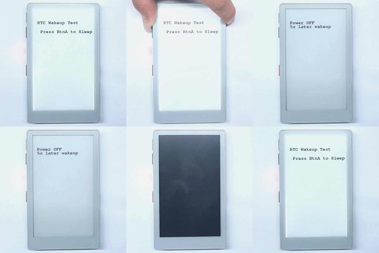
Example description: After the device powers on, click button A to configure RTC timer wakeup, after which the M5PM1 enters sleep. The RTC triggers wakeup after 5s, and the ESP32-S3 powers on again.
#include <M5Unified.h>
#include <M5PM1.h>

M5PM1 pm1;

void setup(void)
{
    auto cfg = M5.config();
    cfg.clear_display = false;
    M5.begin(cfg);
    Serial.begin(115200);

    // Initialize PM1
    m5pm1_err_t err = pm1.begin(&M5.In_I2C, M5PM1_DEFAULT_ADDR, M5PM1_I2C_FREQ_100K);

    if (err == M5PM1_OK) {
        Serial.println("PM1 initialization successful");
        pm1.gpioSetWakeEnable(M5PM1_GPIO_NUM_0, true);
        pm1.gpioSetWakeEdge(M5PM1_GPIO_NUM_0, M5PM1_GPIO_WAKE_FALLING);  // Falling edge
    } else {
        Serial.printf("PM1 initialization failed, error code: %d\n", err);
    }

    M5.Display.setEpdMode(epd_mode_t::epd_fast);
    M5.Display.setFont(&fonts::FreeMonoBold18pt7b);
    M5.Display.clear();
    M5.Display.setCursor(40, 100);
    M5.Display.printf("RTC Wakeup Test\n\n");
    M5.Display.println("   Press BtnA to Sleep");
}

void loop(void)
{
    M5.update();
    if (M5.BtnA.wasPressed()) {
        M5.Rtc.clearIRQ();

        if (M5.Rtc.setTimerIRQ(5000)){// 5s later wakeup
            Serial.println("RTC IRQ enabled successfully");
            M5.Display.clear();
            M5.Display.setCursor(40, 100);
            M5.Display.printf("Power OFF");
            M5.Display.setCursor(40, 130);
            M5.Display.printf("5s later wakeup");
            // Shutdown
            pm1.setLdoEnable(true);
            pm1.ldoSetPowerHold(true);
            pm1.setLedEnLevel(true);
            delay(500);
            pm1.shutdown();
        } else {
            Serial.println("Failed to enable RTC IRQ");
        }
    }
}After button A is pressed, the program clears the RTC interrupt and sets a 5-second timer, then powers off the device while retaining M5PM1 L1 power. When the timer expires, the RTC triggers a falling-edge wakeup through M5PM1 GPIO0. The M5PM1 restores power, and the ESP32-S3 runs initialization again.
Waking the ESP32-S3 with the RTC
The RTC wakeup procedure is similar to IMU wakeup for the ESP32-S3. The difference is that RTC wakeup does not require configuring a BMI270 interrupt, but it still depends on the RTC IRQ → M5PM1 GPIO → PYG1_IRQ → ESP32-S3 G1 signal path.
#include <M5Unified.h>
#include <M5PM1.h>
#include "driver/rtc_io.h"

M5PM1 pm1;

void setup(void) {
  auto cfg = M5.config();
    cfg.clear_display = false;
    cfg.disable_rtc_irq = false;
    M5.begin(cfg);
    Serial.begin(115200);

    // Initialize PM1
    m5pm1_err_t err = pm1.begin(&M5.In_I2C, M5PM1_DEFAULT_ADDR, M5PM1_I2C_FREQ_100K);

    if (err == M5PM1_OK) {
        Serial.println("PM1 initialization successful");
        pm1.irqClearGpioAll();
        pm1.irqClearSysAll();
        pm1.irqClearBtnAll();

        pm1.irqSetGpioMaskAll(M5PM1_IRQ_MASK_ENABLE);
        pm1.irqSetSysMaskAll(M5PM1_IRQ_MASK_ENABLE);
        pm1.irqSetBtnMaskAll(M5PM1_IRQ_MASK_ENABLE);

        pm1.irqSetGpioMask(M5PM1_IRQ_GPIO0, M5PM1_IRQ_MASK_DISABLE);
        pm1.gpioSetMode(M5PM1_GPIO_NUM_0, M5PM1_GPIO_MODE_INPUT);
        pm1.gpioSetPull(M5PM1_GPIO_NUM_0, M5PM1_GPIO_PULL_UP);

        pm1.gpioSetMode(M5PM1_GPIO_NUM_1, M5PM1_GPIO_MODE_OUTPUT);
        pm1.gpioSetDrive(M5PM1_GPIO_NUM_1, M5PM1_GPIO_DRIVE_PUSHPULL);
        pm1.gpioSetFunc(M5PM1_GPIO_NUM_1, M5PM1_GPIO_FUNC_IRQ);
    } else {
        Serial.printf("PM1 initialization failed, error code: %d\n", err);
    }

    M5.Display.setEpdMode(epd_mode_t::epd_fast);
    M5.Display.setFont(&fonts::FreeMonoBold18pt7b);
    M5.Display.clear();
    M5.Display.setCursor(40, 100);
    M5.Display.printf("RTC IRQ Test\n\n");
    M5.Display.println("   Press BtnA to Sleep");
    delay(200);
    M5.Rtc.clearIRQ();
    delay(200);
}

volatile bool pm1IrqTriggered = false;

void ARDUINO_ISR_ATTR pm1_irq_handler() {
    pm1IrqTriggered = true;
}

void loop(void) {
    M5.update();

    if (pm1IrqTriggered) {
        pm1IrqTriggered = false;
        M5.Rtc.clearIRQ();
        pm1.irqClearGpioAll();
        pm1.irqClearSysAll();
        pm1.irqClearBtnAll();
        Serial.println("PM1 IRQ triggered");
        M5.Display.setCursor(40, 140);
        M5.Display.println("PM1 IRQ triggered");
    }

    if (M5.BtnA.wasPressed()) {
        if (M5.Rtc.setTimerIRQ(5000)){// Set Timer IRQ
            Serial.println("RTC IRQ enabled successfully");
            M5.Display.clear();
            M5.Display.setCursor(40, 100);
            M5.Display.printf("Wait for IRQ ...");

            // Choose either of the two pieces of code below.
            pinMode(GPIO_NUM_1, INPUT_PULLUP);
            attachInterrupt(GPIO_NUM_1, pm1_irq_handler, FALLING);

            // esp_sleep_enable_ext0_wakeup(GPIO_NUM_1, 0);  // 0 = Low
            // rtc_gpio_pullup_en(GPIO_NUM_1);
            // Serial.println("Going to sleep now");
            // esp_deep_sleep_start();
        } else {
            Serial.println("Failed to enable RTC IRQ");
        }
    }
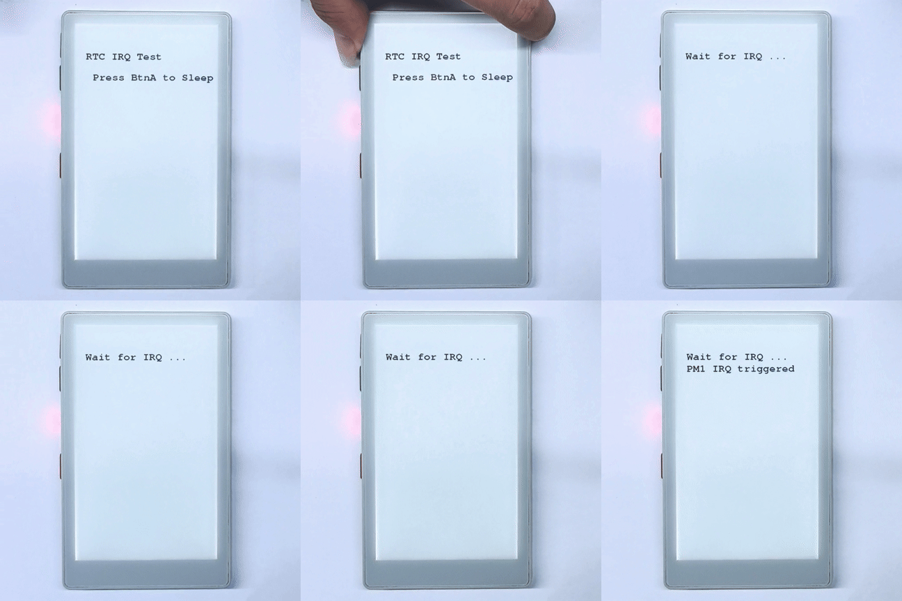
}After button A is pressed, the program sets a 5-second RTC interrupt and uses the M5PM1 to forward the GPIO0 interrupt to ESP32-S3 G1. By default, the current code displays the trigger result using a falling-edge interrupt on G1. If the commented deep-sleep section is enabled, the RTC wakes the ESP32-S3 when the timer expires, and execution restarts from setup().
6. M5IOE1 Peripheral Control
The PaperMono M5IOE1 controls peripherals at level L3B. The primary M5IOE1 pins are listed below:
| M5IOE1 Pin | PaperMono Function |
|---|---|
M5IOE1_PIN_2 | LoRa antenna switch |
M5IOE1_PIN_3 | E-paper power |
M5IOE1_PIN_4 | NFC/RFID enable |
M5IOE1_PIN_5 | E-paper reset |
M5IOE1_PIN_6 | Touch reset |
M5IOE1_PIN_8 | RGB LED green channel |
M5IOE1_PIN_9 | RGB LED blue channel |
M5IOE1_PIN_10 | LoRa reset |
M5IOE1_PIN_12 | PDM microphone power |
M5IOE1_PIN_13 | Touch power |
M5IOE1_PIN_14 | microSD power |
The following example initializes M5PM1 and M5IOE1 directly, then demonstrates the display frontlight, LoRa antenna switch and reset, NFC power, and RGB LED green and blue channel control in sequence. The pins associated with the e-paper display, touch controller, microSD, and PDM microphone are already used by M5Unified. Before modifying them, ensure that the corresponding peripheral has stopped, or the peripheral may stop working or require reinitialization.
#include <M5Unified.h>
#include <M5PM1.h>
#include <M5IOE1.h>

M5PM1 pm1;
M5IOE1 ioe1;

#define IOE_LORA_ANT_SW M5IOE1_PIN_2
#define IOE_LORA_RST    M5IOE1_PIN_10
#define IOE_NFC_EN      M5IOE1_PIN_4
#define IOE_LED_G       M5IOE1_PIN_8
#define IOE_LED_B       M5IOE1_PIN_9

void setup(void)
{
    auto cfg = M5.config();
    cfg.clear_display = false;
    M5.begin(cfg);
    Serial.begin(115200);

    // Initialize PM1.
    const m5pm1_err_t pm1_err =
        pm1.begin(&M5.In_I2C, M5PM1_DEFAULT_ADDR, M5PM1_I2C_FREQ_100K);
    if (pm1_err == M5PM1_OK) {
        Serial.println("PM1 initialization successful");
    } else {
        Serial.printf("PM1 initialization failed, error code: %d\n", pm1_err);
    }
    pm1.setSingleResetDisable(false);

    // Enable the PaperMono LoRa power rail through PM1 GPIO2.
    pm1.gpioSetFunc(M5PM1_GPIO_NUM_2, M5PM1_GPIO_FUNC_GPIO);
    pm1.gpioSetMode(M5PM1_GPIO_NUM_2, M5PM1_GPIO_MODE_OUTPUT);
    pm1.gpioSetDrive(M5PM1_GPIO_NUM_2, M5PM1_GPIO_DRIVE_PUSHPULL);
    pm1.gpioSetOutput(M5PM1_GPIO_NUM_2, true);

    // Initialize IOE1.
    const m5ioe1_err_t ioe1_err =
        ioe1.begin(&M5.In_I2C, M5IOE1_DEFAULT_ADDR, M5IOE1_I2C_FREQ_100K);
    if (ioe1_err == M5IOE1_OK) {
        Serial.println("IOE1 initialization successful");
    } else {
        Serial.printf("IOE1 initialization failed, error code: %d\n", ioe1_err);
        while (true) delay(1000);
    }

    ioe1.pinMode(IOE_LORA_ANT_SW, OUTPUT);
    ioe1.pinMode(IOE_LORA_RST, OUTPUT);
    ioe1.pinMode(IOE_NFC_EN, OUTPUT);
    ioe1.pinMode(IOE_LED_G, OUTPUT);
    ioe1.pinMode(IOE_LED_B, OUTPUT);

    // Default states: LoRa receive path, LoRa released from reset, NFC on, LEDs off.
    ioe1.digitalWrite(IOE_LORA_ANT_SW, LOW);
    ioe1.digitalWrite(IOE_LORA_RST, HIGH);
    ioe1.digitalWrite(IOE_NFC_EN, HIGH);
    ioe1.digitalWrite(IOE_LED_G, LOW);
    ioe1.digitalWrite(IOE_LED_B, LOW);

    M5.Display.setEpdMode(epd_mode_t::epd_fast);
    M5.Display.setFont(&fonts::FreeMonoBold18pt7b);
    M5.Display.clear();
    M5.Display.setCursor(40, 100);
    M5.Display.printf("IOE1 Power Test Begin\n\n");
    delay(1000);
}

void loop(void)
{
    M5.update();

    // Display frontlight.
    M5.Display.clear();
    M5.Display.setCursor(40, 100);
    M5.Display.printf("Frontlight OFF");
    M5.Display.setBrightness(0);
    delay(1000);
    M5.Display.setBrightness(255);
    M5.Display.setCursor(40, 140);
    M5.Display.printf("Frontlight ON");
    delay(1000);

    // LoRa antenna switch.
    M5.Display.clear();
    M5.Display.setCursor(40, 100);
    M5.Display.printf("LoRa antenna RX");
    ioe1.digitalWrite(IOE_LORA_ANT_SW, LOW);
    delay(1000);
    M5.Display.setCursor(40, 140);
    M5.Display.printf("LoRa antenna TX");
    ioe1.digitalWrite(IOE_LORA_ANT_SW, HIGH);
    delay(1000);

    // LoRa reset.
    M5.Display.clear();
    M5.Display.setCursor(40, 100);
    M5.Display.printf("LoRa reset LOW");
    ioe1.digitalWrite(IOE_LORA_RST, LOW);
    delay(100);
    M5.Display.setCursor(40, 140);
    M5.Display.printf("LoRa reset HIGH");
    ioe1.digitalWrite(IOE_LORA_RST, HIGH);
    delay(1000);

    // NFC power enable.
    M5.Display.clear();
    M5.Display.setCursor(40, 100);
    M5.Display.printf("NFC power OFF");
    ioe1.digitalWrite(IOE_NFC_EN, LOW);
    delay(1000);
    M5.Display.setCursor(40, 140);
    M5.Display.printf("NFC power ON");
    ioe1.digitalWrite(IOE_NFC_EN, HIGH);
    delay(1000);

    // RGB LED green and blue channels.
    M5.Display.clear();
    M5.Display.setCursor(40, 100);
    M5.Display.printf("Green LED ON");
    ioe1.digitalWrite(IOE_LED_G, HIGH);
    ioe1.digitalWrite(IOE_LED_B, LOW);
    delay(1000);
    M5.Display.setCursor(40, 140);
    M5.Display.printf("Blue LED ON");
    ioe1.digitalWrite(IOE_LED_G, LOW);
    ioe1.digitalWrite(IOE_LED_B, HIGH);
    delay(1000);
    ioe1.digitalWrite(IOE_LED_G, LOW);
    ioe1.digitalWrite(IOE_LED_B, LOW);
    delay(200);
}After the program is flashed successfully, it first turns the display frontlight off and on, then demonstrates the LoRa antenna switch, LoRa reset, NFC power control, and RGB LED green and blue channel control in sequence.