

Product Guides
AI & Voice
AI Voice Assistants
Volcengine
Offline Speech Recognition
Unit ASR
Module ASR
Audio & Voice Input
Voice Pyramid
Cameras & Vision
Camera Features
M5Camera
PoECAM
Unit CamS3 / CamS3-5MP
Connectivity & IoT
Industrial Control & Measurement
Air Quality
PowerHub
StamPLC
VAMeter
T-Lite
Module13.2 PPS
Unit RollerCAN
Display & Interaction
Paper
PaperColor
StopWatch
Tab5 Keyboard
Chain DualKey
Robotics & Maker Projects
Atom Printer
Bala
Bala2
BalaC Plus
Faces Kit Gameboy
RoverC & JoyC
StampFly & Atom Joystick
Firmware & Device Maintenance
Hardware Configuration
Design & Selection References
AT6668-Based GNSS Device Firmware Upgrade Guide
This guide applies to AT6668-based devices such as Unit GPS v1.1, Unit GPS SMA, and Module GPS v2.0 / v2.1. The upgrade procedure, firmware, and tools are the same across models; only the connector type differs. This guide uses Unit GPS v1.1 as an example to explain the specific upgrade steps and troubleshooting methods.
1. Precautions
To ensure a successful upgrade, do not perform any of the following during the upgrade:
- Power off or reset the device
- Disconnect or reconnect cables or the adapter board
- Close GnssToolKit3
2. Preparation
| Item | Parameter |
|---|---|
| Example Device | Unit GPS v1.1 (SKU: U032-V11) |
| GNSS Module | ATGM336H-6N (based on AT6668) |
| Communication Method | UART, 115200bps @ 8N1 |
| Power Supply | DC 5V |
| Supported Satellite Systems | GPS / QZSS / BD2 / BD3 / GAL / GLO |
| Target Firmware | AT6668-ATGM336H_6N74_V6380_20260525-2800.ubf (V6.3.8.0) |
| Upgrade Tool | GnssToolKit3 (Windows) |
2.1 Bill of Materials
| Item | Description | Quantity |
|---|---|---|
| AT6668 Device to Be Upgraded | This guide uses Unit GPS v1.1 as an example | 1 |
| USB-TTL Module | CH340 / CP2102 / FT232; logic level set to 3.3V | 1 |
| Dupont Wires | Grove to Dupont cable; pin-header devices can be connected directly with Dupont wires | 1 |
| Windows PC | Windows 10 / 11 | 1 |
2.2 Software Preparation
| Software | Description |
|---|---|
| GnssToolKit3 | After extracting, keep the directory structure intact. Do not copy the EXE file by itself. |
| Firmware Package | AT6668-ATGM336H_6N74_V6380_20260525-2800.ubf |
| USB-TTL Driver | Install the driver that matches the adapter board chip. |
2.3 Firmware File
| File | Size | SHA-256 |
|---|---|---|
AT6668-ATGM336H_6N74_V6380_20260525-2800.ubf | 184,664 bytes | 9220d0ef77ebbf5d1a7e16d9fb8cffe8c071d14326eb031f94da78a1993c1e42 |
3. Hardware Connection
3.1 Pin Mapping Table
Using Unit GPS v1.1 as an example, the device provides a HY2.0-4P Grove connector that exposes GND, 5V, and UART signals. For the upgrade, use a Grove to Dupont cable to connect the device to the USB-TTL module. Unit GPS SMA uses exactly the same wiring order.
| Grove Wire Color | Pin | Signal | Direction | Connect to USB-TTL |
|---|---|---|---|---|
| Black | 1 | GND | — | GND |
| Red | 2 | 5V | Power Input | 5V |
| Yellow | 3 | UART_RX | Input | TXD |
| White | 4 | UART_TX | Output | RXD |
Module GPS v2.0 / v2.1 uses a 2.54mm pin header. Connect GND, 5V, TX, and RX according to the silkscreen labels on the board.
Wiring Diagram (TX/RX cross-connected, common ground):
   USB-TTL                        Unit GPS v1.1
  ┌──────────┐                   ┌──────────────┐
  │  5V   ●──┼───────────────────┼──● Red 5V    │
  │  GND  ●──┼───────────────────┼──● Black GND │
  │  RXD  ●──┼───────────────────┼──● White TX  │
  │  TXD  ●──┼───────────────────┼──● Yellow RX │
└──────────┘ └──────────────┘3.2 Wiring Precautions
- TX and RX must be crossed: connect the module TX to the adapter RX, and the module RX to the adapter TX.
- The device and USB-TTL module must share a common ground; connecting only TX/RX may cause communication errors or no data output.
- The signal level is 3.3V; set the USB-TTL module to 3.3V, and never connect RS-232 levels (±12V).
- No antenna or satellite positioning is required during the upgrade; it can be completed indoors.
- For pin-header devices, distinguish the power and signal pins to avoid connecting 5V to TX/RX.
4. Driver Installation and Serial Port Detection
- After installing the USB-TTL driver, connect the USB-TTL module to the computer and open Device Manager.
- Under Ports (COM & LPT), confirm the newly added serial device, such as
USB-SERIAL CH340 (COMx), and note its port number. - Close any program that is using the port, such as a serial terminal or an IDE serial monitor.
Serial Port Settings:
| Parameter | Value |
|---|---|
| Baud Rate | 115200 |
| Data Bits | 8 |
| Parity | None |
| Stop Bits | 1 |
| Flow Control | None |
Serial port resource error., another program is using the port. Close the program and reconnect.5. Firmware Upgrade
Complete the wiring described in Chapter 3 and power on the module.
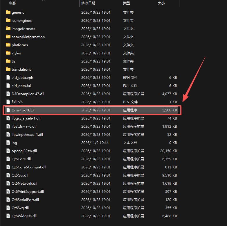
Open the GnssToolKit3 directory and double-click
GnssToolKit3.exeto run it.
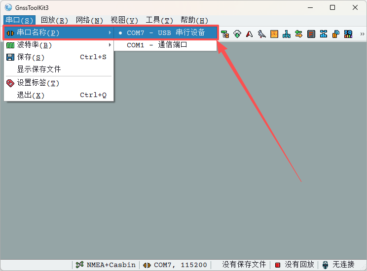
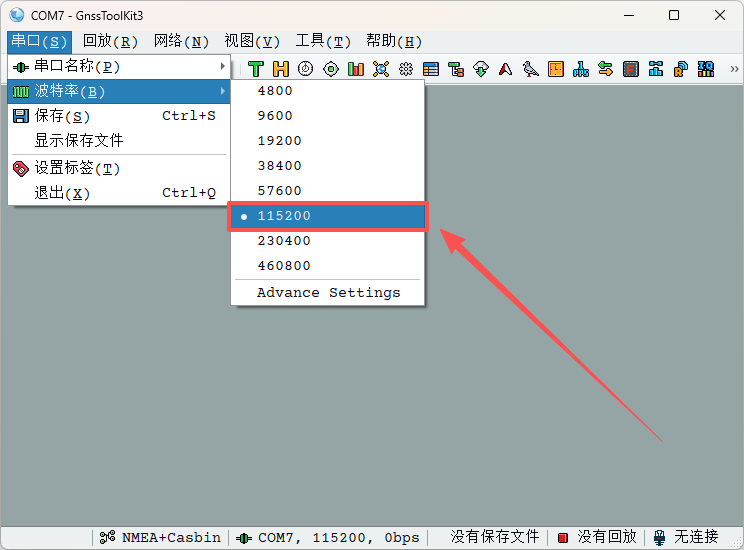
- Select the corresponding COM port from the port list, set the baud rate to
115200, and click连接(Connect).
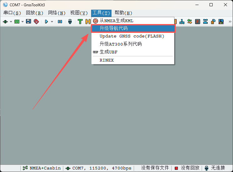
- Click
升级导航代码(Upgrade Navigation Code) to open the firmware upgrade page.
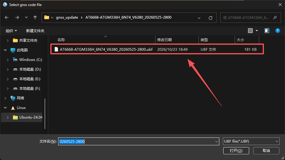
- Select the firmware file
AT6668-ATGM336H_6N74_V6380_20260525-2800.ubf, and confirm that the module model and firmware version areV6.3.8.0.
- Wait for the upgrade to complete.

- After a successful upgrade, power off the module and power it on again to complete the restart.

6. FAQ
COM Port Not Displayed in Device Manager
- Reinstall the USB-TTL driver.
- Try another USB cable and USB port.
The Tool Reports That the Serial Port Cannot Be Opened
- Close serial terminals, IDE serial monitors, and other programs that are using the port.
- If the log shows
Serial port resource error., the port is in use.
No Output After Opening the Serial Port
- Check whether TX/RX are crossed.
- Confirm that the module and adapter board share a common ground.
- Confirm that the baud rate is 115200.
Garbled Serial Output
- Set the serial port parameters to 115200 8N1.
Upgrade Fails Midway
- Check for loose wiring and unstable power.
- Power cycle the module and perform the upgrade again.
No Data Output from Module GPS
- Check the DIP switch TX/RX setting against the board silkscreen, and connect to the corresponding pins.