


Product Guide
Linux PC
CardputerZero
AI Accelerator Card
LLM-8850 Card
Large Language Models
AI & Agent
Real-Time AI Voice Assistant
XiaoZhi Voice Assistant
AtomS3R-M12 Volcengine Kit
Offline Voice Recognition
Industrial Control
IoT Measuring Instruments
Air Quality
PowerHub
Module13.2 PPS
VAMeter
T-Lite
Display Devices
PaperColor
Ethernet Camera
PoECAM
Wi-Fi Camera
Unit CamS3/-5MP
AI Camera
LoRa & LoRaWAN
Motor Control
Restore Factory Firmware
DIP Switch Usage Guide
V-function
Function
V-Function is developed by M5Stack team for M5StickV/UnitV devices with multiple visual recognition firmware, the camera outputs recognition result via `serial port (115200bps) after completing the visual recognition, based on the different functions of the firmware (object tracking, motion detection, etc.), the user is able to quickly carry out the function of visual recognition. This tutorial will introduce you to the visual recognition functions. This tutorial will show you how to burn firmware into your device and call it through UIFlow graphical programming.
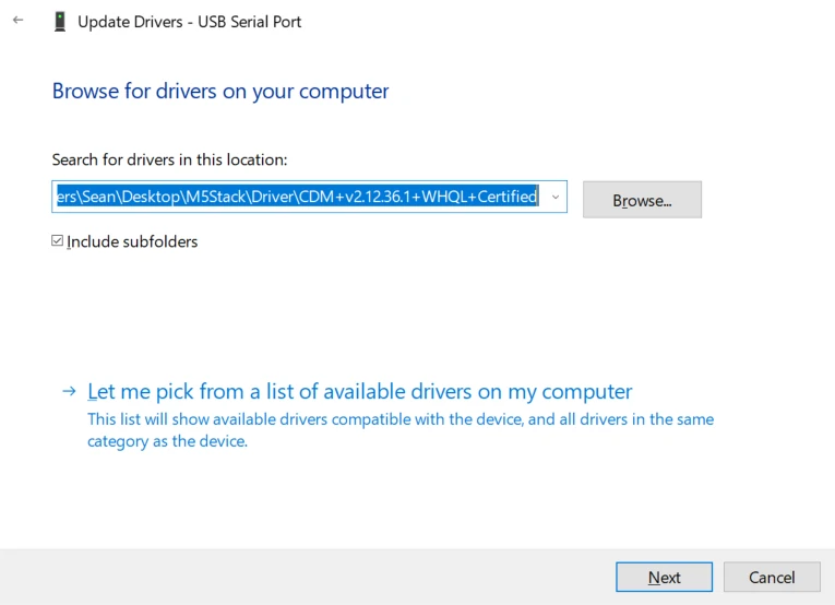
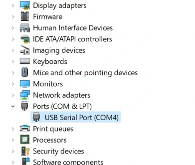
Driver Installation
M5Stack or USB Serial, Windows recommend to use the driver file in the device manager to install it directly (customize the update), the executable file installation method may not work properly). Click here to go to download FTDI driver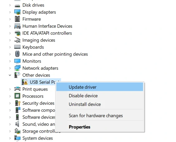
System Preferences - > Security & Privacy - > General - > Apps allowed to be downloaded from the following locations - > App Store and Approved Developer Options.Burning Firmware
Please click the button below to download the appropriate M5Burner firmware burning tool for your operating system. Unzip and open the application.
| Software Version | Download Link |
|---|---|
| M5Burner_Windows | Download |
| M5Burner_MacOS | Download |
| M5Burner_Linux | Download |
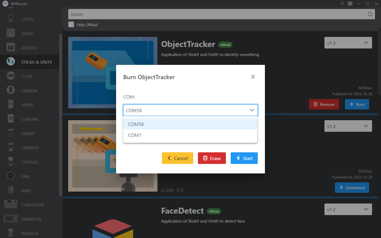
Select M5StickV/UnitV as the device on the left side of the device column, select the corresponding function firmware according to the usage requirements, and download it. Connect the M5StickV/UnitV to the computer via cable, select its corresponding port and click Burn to start burning.
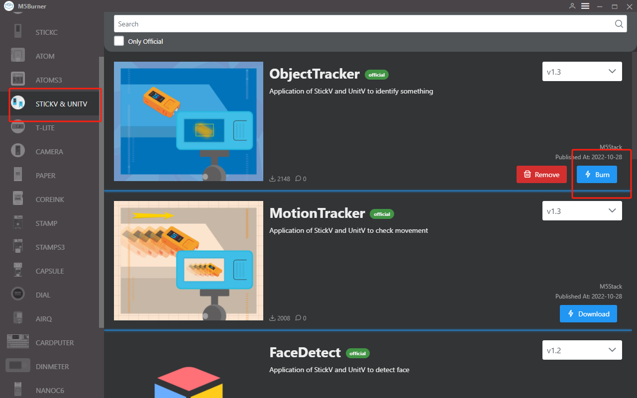
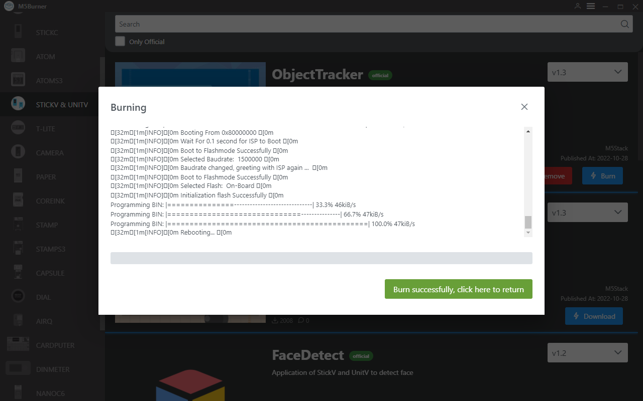
When the burn log prompts Burn Successfully, it means the firmware has been burned.
UIFlow
M5StickV/UnitV after burning the functional firmware will be used as a slave device in the form of Unit, so users need to use other M5 host devices to interact with it. For the basic use and operation of UIFlow on other host devices, please visit their corresponding product documentation page.
Go to https://flow.m5stack.com/ to enter UIFlow. Tap the Add Unit button on the left panel, and select UnitV to add. Please configure the port according to the actual port. Click OK to add.
Once added, the included function block can be found in the function block menu under the Unit option. Drag and drop the block into the programming area on the right to use it. For a detailed description of the block's functions, click on the UIFlow Block documentation below.
Motion Detection
Detects changes in the current screen and determines whether or not there is movement of objects in the detection area.
Motion Detection - Data Packet Format
Return JSON
{
    "FUNC": "MOTION DETECT V1.0",
    "DIFF TOTAL": 10000, // Frame change rate
    "DIFF MAX": 75, // Maximum change rate
    "TOTAL": 3, // Number of boundary boxes
    "0": {
        "x": 45,
        "y": 18,
        "w": 126,
        "h": 72,
        "area": 342 // Number of changed pixels in this boundary box
    },
    "1": {
        "x": 0,
        "y": 169,
        "w": 130,
        "h": 24,
        "area": 173
    },
    "2": {
        "x": 39,
        "y": 204,
        "w": 276,
        "h": 34,
        "area": 141
    }
}
Setting CMD JSON
{
    "MOTION DETECT": 1.0, // Function flag, cannot be omitted
    "mode": "COMPUTE_MODE_STATIC", // Optional "COMPUTE_MODE_STATIC" static detection mode or "COMPUTE_MODE_DYNAMIC" dynamic detection mode
    "thr_w": 20, // Optional Width threshold of the boundary box,[3,200]
    "thr_h": 20, // Optional Height threshold of the boundary box,[3,200]
    "stepx": 1, // Optional X-axis scan interval,[0, 40], set to 0 to disable boundary box detection
    "stepy": 2, // Optional Y-axis scan interval,[0, 40], set to 0 to disable boundary box detection
    "delta": 20, // Optional Change rate threshold,[0, 99]
     "merge": 10 // Optional Boundary box merge threshold,[0, 40]
}
TARGET TRACKER
Set the tracking target and get the position information of the target object in the screen in real time.
TARGET TRACKER-Data Packet Format
Return JSON
{
    "FUNC": "TARGET TRACKER V1.0",
    "x": 282,
    "y": 165,
    "w": 13,
    "h": 15
}
Setting CMD JSON
{
    "TARGET TRACKER": " V1.0",
    "x": 282, //xywh cannot be omitted
    "y": 165,
    "w": 13,
    "h": 15
}
COLOR TRACKER
Set the LAB color threshold, track the target that meets the threshold in the screen, and obtain the position information of the target object in the screen in real time.
COLOR TRACKER-Data Packet Format
Return JSON
{
    "FUNC": "COLOR TRACKER V1.0",
    "TOTAL": 3, // Number of boundary boxes
    "0": {
        "x": 45,
        "y": 18,
        "w": 126,
        "h": 72,
        "area": 342 // Number of changed pixels in this boundary box
    },
    "1": {
        "x": 0,
        "y": 169,
        "w": 130,
        "h": 24,
        "area": 173
    },
    "2": {
        "x": 39,
        "y": 204,
        "w": 276,
        "h": 34,
        "area": 141
    }
}
Setting CMD JSON
{
    "COLOR TRACKER": 1.0, // Function flag, cannot be omitted
    "thr_w": 20, // Optional Width threshold of the boundary box,[3,200]
    "thr_h": 20, // Optional Height threshold of the boundary box,[3,200]
    "stepx": 1, // Optional X-axis scan interval,[0, 40], set to 0 to disable boundary box detection
    "stepy": 2, // Optional Y-axis scan interval,[0, 40], set to 0 to disable boundary box detection
    "merge": 10, // Optional Boundary box merge threshold,[0, 40]
    "Lmin": 0, // Optional L threshold lower limit [0, 100]
    "Lmax": 0, // Optional L threshold upper limit [0, 100]
    "Amin": 0, // Optional A threshold lower limit [0, 255]
    "Amax": 0, // Optional A threshold upper limit [0, 255]
    "Bmin": 0, // Optional B threshold lower limit [0, 255]
    "Bmax": 0, // Optional B threshold upper limit [0, 255]
}
FACE DETECT
Recognize the face information in the screen, and return the number of recognition, object coordinates, confidence rate.
FACE DETECT-Data Packet Format
Return JSON
{
   "FUNC": "FACE DETECT",
   "count": 3,
   "2": {
      "x": 97,
      "y": 26,
      "w": 64,
      "h": 86,
      "value": 0.859508,
      "classid": 0,
      "index": 2,
      "objnum": 3
   },
   "1": {
      "x": 70,
      "y": 157,
      "w": 38,
      "h": 63,
      "value": 0.712100,
      "classid": 0,
      "index": 1,
      "objnum": 3
   },
   "0": {
      "x": 199,
      "y": 145,
      "w": 31,
      "h": 40,
      "value": 0.859508,
      "classid": 0,
      "index": 0,
      "objnum": 3
   }
}
QRCode
Recognizes the QR code on the screen, and returns the result, as well as the version. Use firmware Find code
Return JSON
{
   "count": 1,
   "FUNC": "FIND QRCODE",
   "0": {
      "x": 57,
      "y": 16,
      "w": 197,
      "h": 198,
      "payload": "m5stack",
      "version": 1,
      "ecc_level": 1,
      "mask": 2,
      "data_type": 4,
      "eci": 0
   }
}
Bar code
Recognizes barcodes on the screen and returns the result, as well as the version. Using firmware Find code
Return JSON
{
    "0": {
        "x": 62,
        "y": 90,
        "w": 100,
        "h": 45,
        "payload": "123",
        "type": 15,
        "rotation": 0.000000,
        "quality": 28
    },
    "count": 1,
    "FUNC": "FIND BARCODE"
}
Datamatrix Code
Recognizes the Datamatrix code in the screen, and returns the recognition result, as well as the code rotation angle and coordinate data. Use firmware Find code.
Return JSON
{
    "0": {
        "x": 20,
        "y": 116,
        "w": 96,
        "h": 96,
        "payload": "m5stack",
        "rotation": 1.588250,
        "rows": 16,
        "columns": 16,
        "capacity": 12,
        "padding": 1
    },
    "count": 1,
    "FUNC": "FIND DATAMATRIX"
}
Apriltag Code
Identify the Apriltag code in the screen (only Tag36H11 type is supported), and get the offset of its position. Use firmware Find code
Return JSON
{
    "0": {
        "x": 71,
        "y": 5,
        "w": 85,
        "h": 88,
        "id": 1,
        "family": 16,// AprilTag category
        "cx": 115,
        "cy": 49,
        "rotation": 6.219228,// Rotation angle of AprilTag in radians (int).
        "decision_margin": 0.451959,// Color saturation of AprilTag matching (values from 0.0 to 1.0), where 1.0 is optimal.
        "hamming": 0,// Acceptable number of bit errors for AprilTag
        "goodness": 0.000000, // Color saturation of AprilTag image
        "x_translation": 0.868200, // Number of units to move the image left or right after rotation
        "y_translation": 0.245313,// Number of units to move the image up or down after rotation
        "z_translation": -2.725188,// Amount scaled by the image. Default is 1.0
        "x_rotation": 3.093776,// Degrees to rotate the image around the x-axis in the frame buffer
        "y_rotation": 0.065489,// Degrees to rotate the image around the y-axis in the frame buffer
        "z_rotation": 6.219228 // Degrees to rotate the image around the z-axis in the frame buffer
    },
    "count": 1,
    "FUNC": "FIND APRILTAG"
}
Setting CMD JSON
The above multiple identification code functions are all realized by the same firmware Find Code, and the user can configure the mode switching by sending the JSON data below.
{
    "FIND CODE": 1.0,
    "mode":"DATAMATRIX" // Recognition mode, options: QRCODE, APRILTAG, DATAMATRIX, BARCODE
}TAG READER
Detects the label card in the screen and returns the binary sequence. Note: Only fixed label card format is recognized, please refer to the picture below.
TAG READER-Data Packet Format
Return JSON
{
    "FUNC": "TAG READER V2.0",
    "TOTAL": 1,
    "0": {
        "x": 113,
        "y": 65,
        "w": 117,
        "h": 105,
        "p0x": 113, // Coordinates of the 4 vertices of the TAG
        "p0y": 77,
        "p1x": 211,
        "p1y": 65,
        "p2x": 230,
        "p2y": 156,
        "p3x": 127,
        "p3y": 170,
        "rotation": 8, // Relative rotation angle of the TAG
        "rows": 8, // Number of rows of the TAG (excluding the locator frame)
        "columns": 8, // Number of columns of the TAG (excluding the locator frame)
        "size": 64, // Length of the actual content of the TAG, this value = number of rows * number of columns = (rows) * (columns)
        "code": "0x003C42425A424200", // uint64_t type content binary code, maximum encoding of 64 bits (8 x 8) TAG
        "binstr": "0000000000111100010000100100001001011010010000100100001000000000" // Binary data string, this value can encode TAGs of any length and width
    }
}
LINE TRACKER
Detects the specified color line in the screen and returns the offset angle.
LINE TRACKER-Data Packet Format
Return JSON
{
    "FUNC": "LINE TRACKER V1.0",
    "angle": 3.8593475818634033 // Angle of turning the car
}Setting CMD JSON
{
    "LINE  TRACKER": 1.0, // Function flag, cannot be omitted
    "thr_w": 20, // Optional, width threshold of the boundary box, [3,200]
    "thr_h": 20, // Optional, length threshold of the boundary box, [3,200]
    "stepx": 1, // Optional, X scan interval, [0, 40], set to 0 to disable boundary box detection
    "stepy": 2, // Optional, Y scan interval, [0, 40], set to 0 to disable boundary box detection
    "merge": 10, // Optional, boundary box merge threshold, [0, 40]
    "Lmin": 0, // Optional, L threshold lower limit [0, 100]
    "Lmax": 0, // Optional, L threshold upper limit [0, 100]
    "Amin": 0, // Optional, A threshold lower limit [0, 255]
    "Amax": 0, // Optional, A threshold upper limit [0, 255]
    "Bmin": 0, // Optional, B threshold lower limit [0, 255]
    "Bmax": 0, // Optional, B threshold upper limit [0, 255]
    "weight_0": 0.1, // Optional, weight
    "weight_1": 0.3, // Optional, weight
    "weight_2": 0.7  // Optional, weight
}Related content
FAQ
After connecting the slave device (M5StickV/UnitV) to the master, if the master does not get the data properly, please restart the M5StickV/UnitV and wait for the firmware to start successfully and try to connect again.