Product Guide
Linux PC
CardputerZero
AI Accelerator Card
LLM-8850 Card
Large Language Models
AI & Agent
Real-Time AI Voice Assistant
XiaoZhi Voice Assistant
AtomS3R-M12 Volcengine Kit
Offline Voice Recognition
Industrial Control
IoT Measuring Instruments
Air Quality
PowerHub
Module13.2 PPS
VAMeter
T-Lite
Ethernet Camera
PoECAM
Wi-Fi Camera
Unit CamS3/-5MP
AI Camera
LoRa & LoRaWAN
Motor Control
Restore Factory Firmware
DIP Switch Usage Guide
LoRaWAN470 Gateway & Node
1. Step 1: Preparation
1.1 Hardware preparation
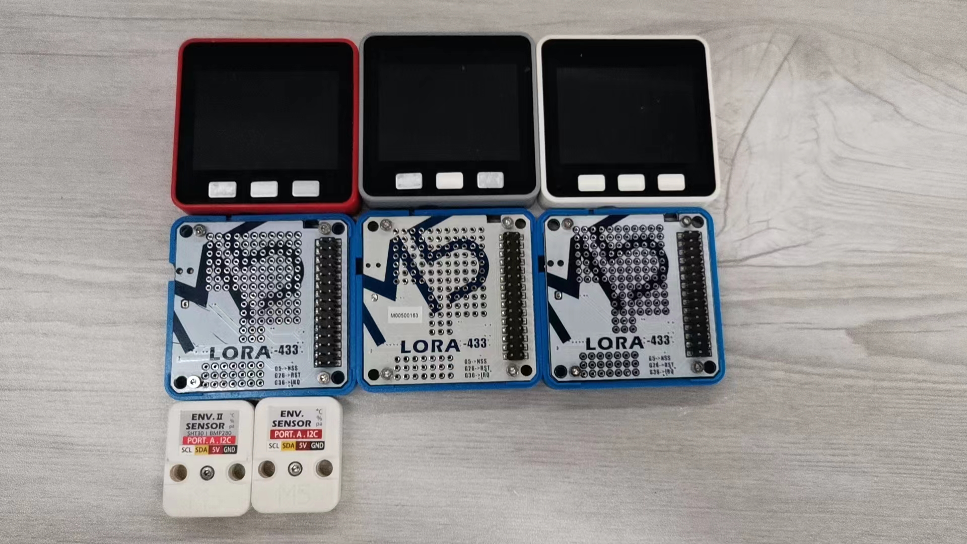
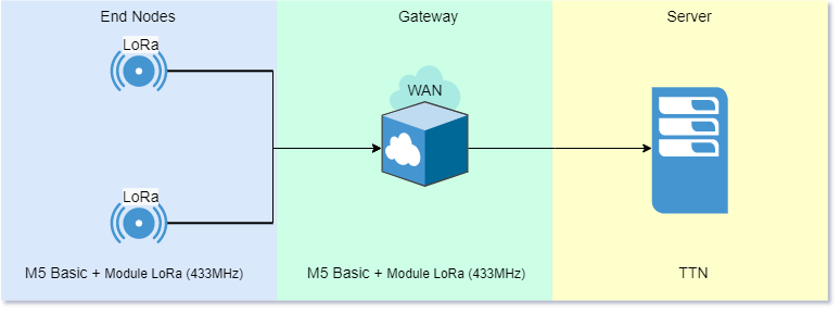
- BASIC Host: 3 (1 gateway 2 nodes)
- Module LoRa (433MHz): 3 (1 gateway 2 nodes)
- ENV-II Unit: 2
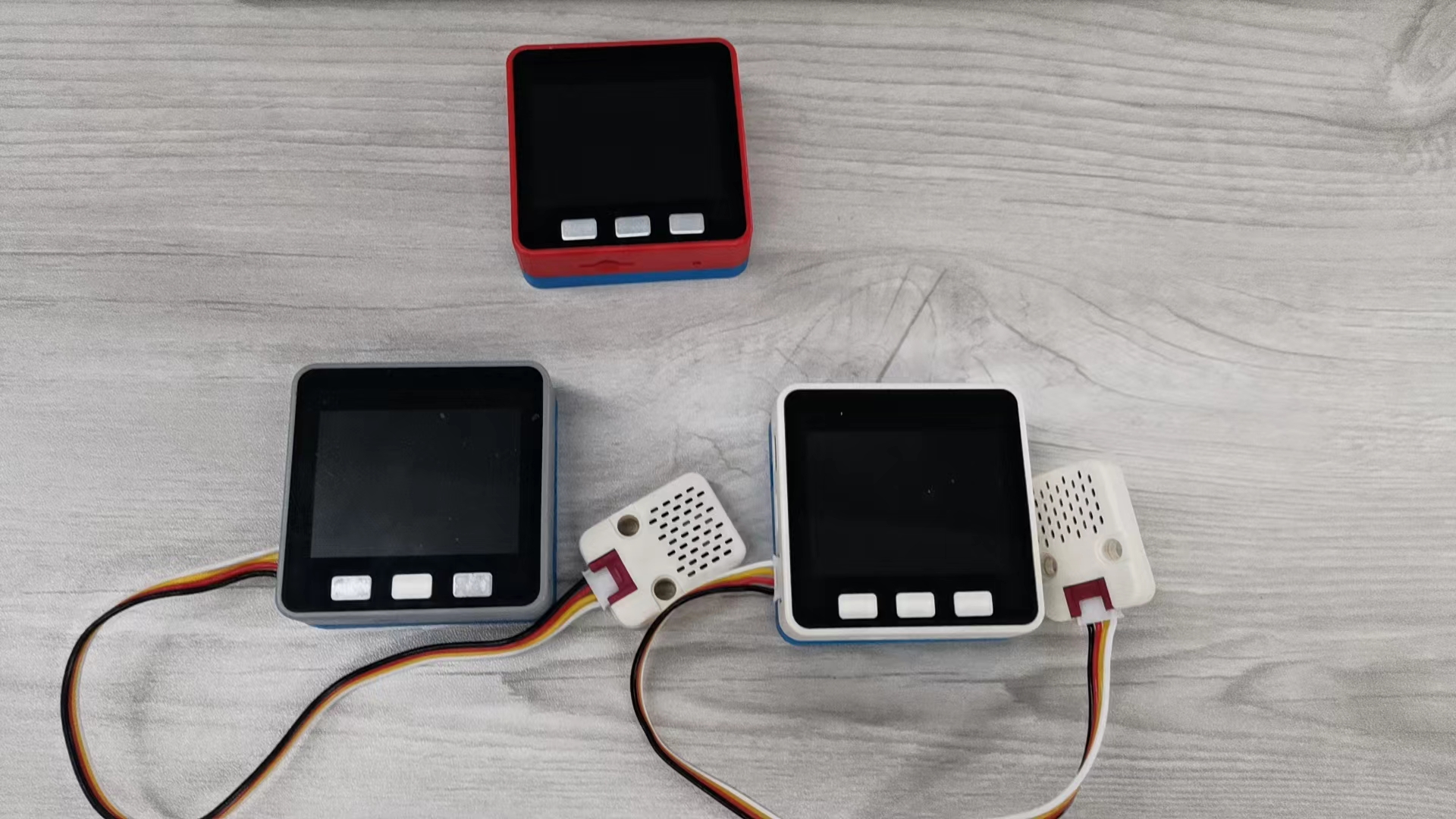
Assemble the 433 Module, ENV-II Unit and core mainframe, where two of them are used as LoRaWan terminals and one of them is used as LoRaWan gateway.
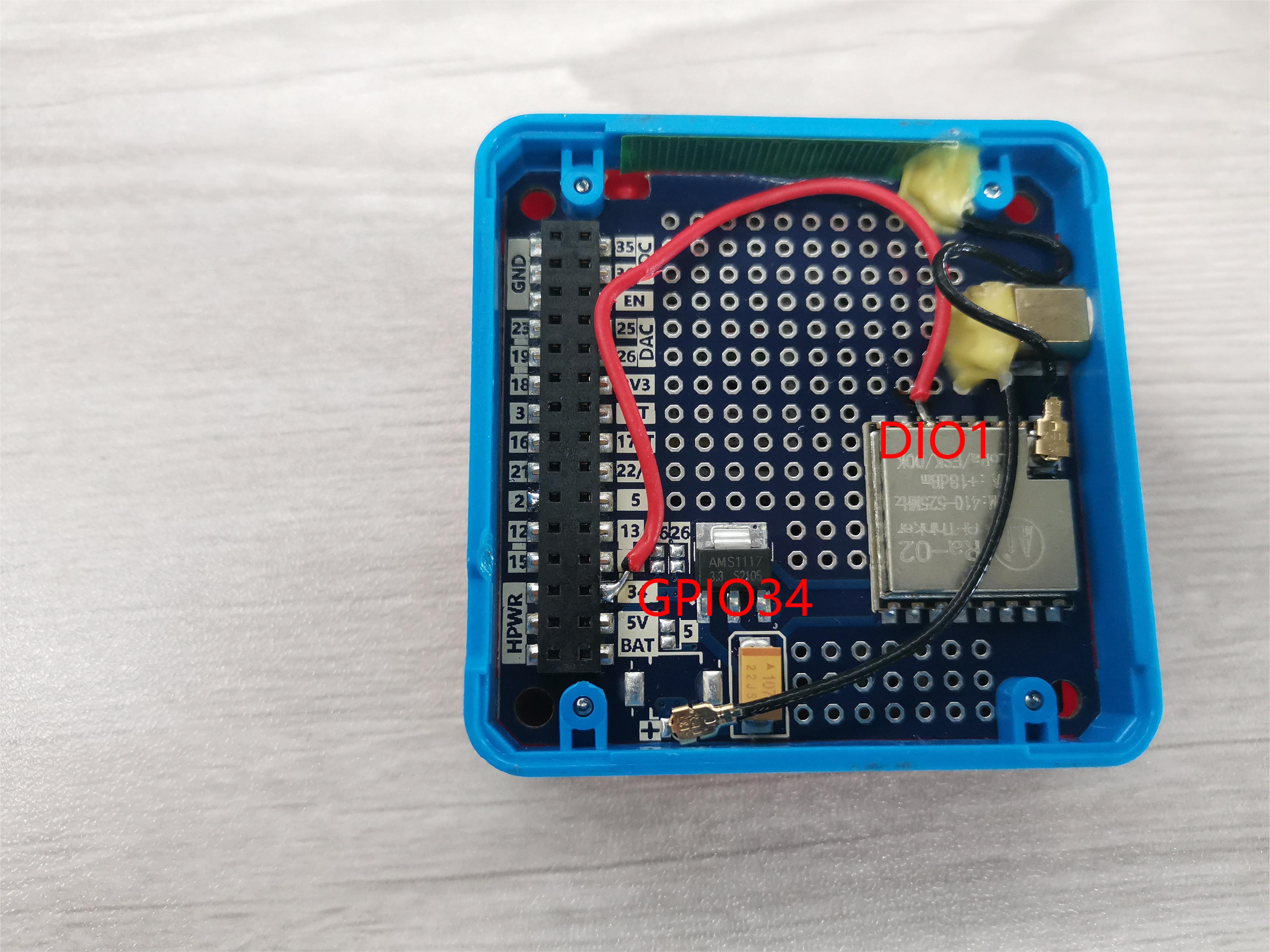
Note: Module LoRa (433MHz) module requires DIO1 to GPIO34 connection.
2. Step 2: Firmware burning and configuration
2.1 Gateway
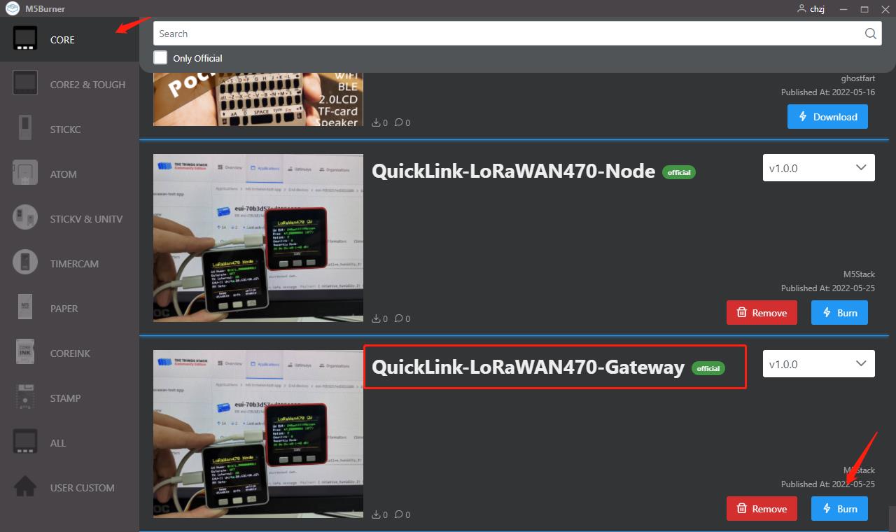
2.1.1 Gateway firmware burning and configuration
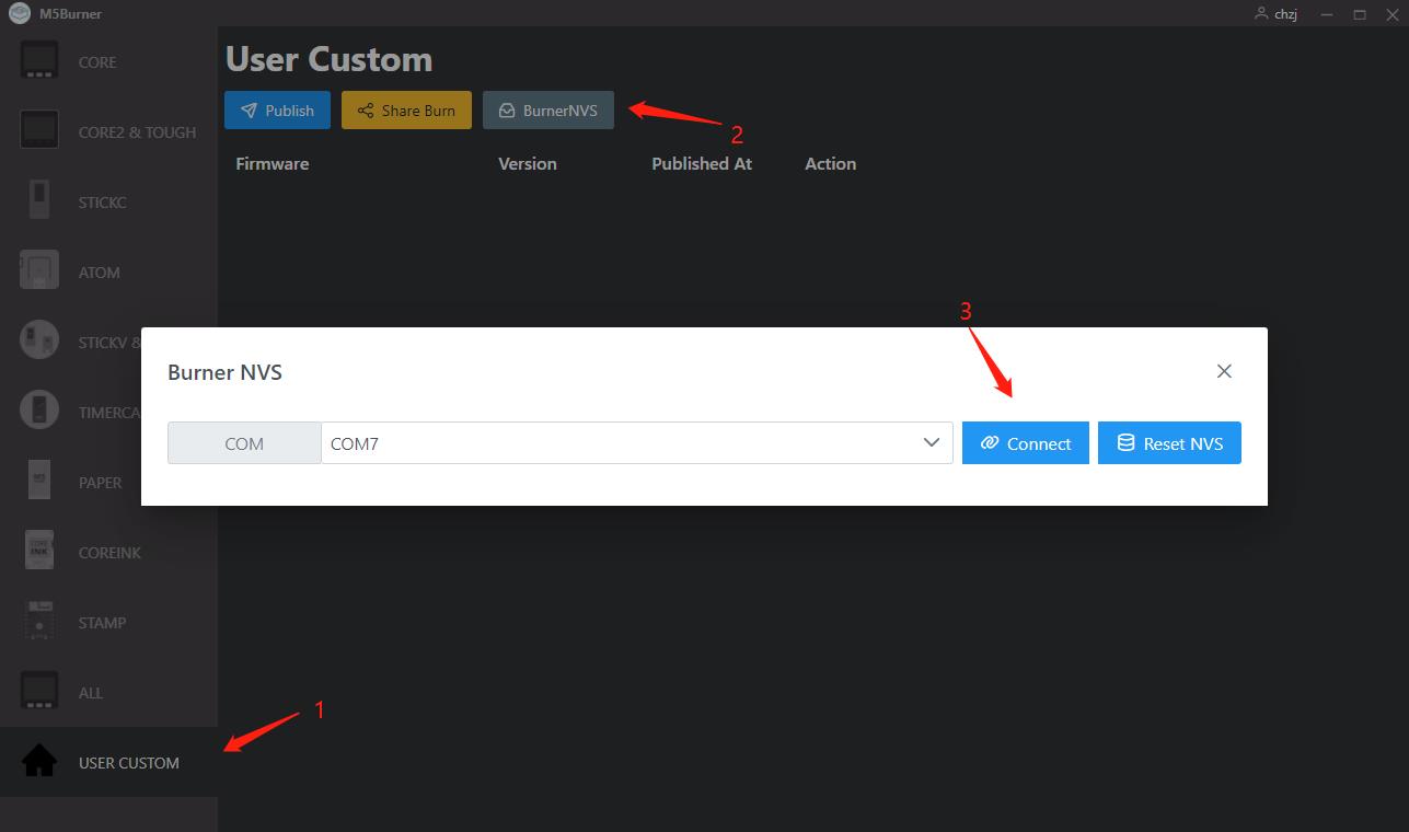
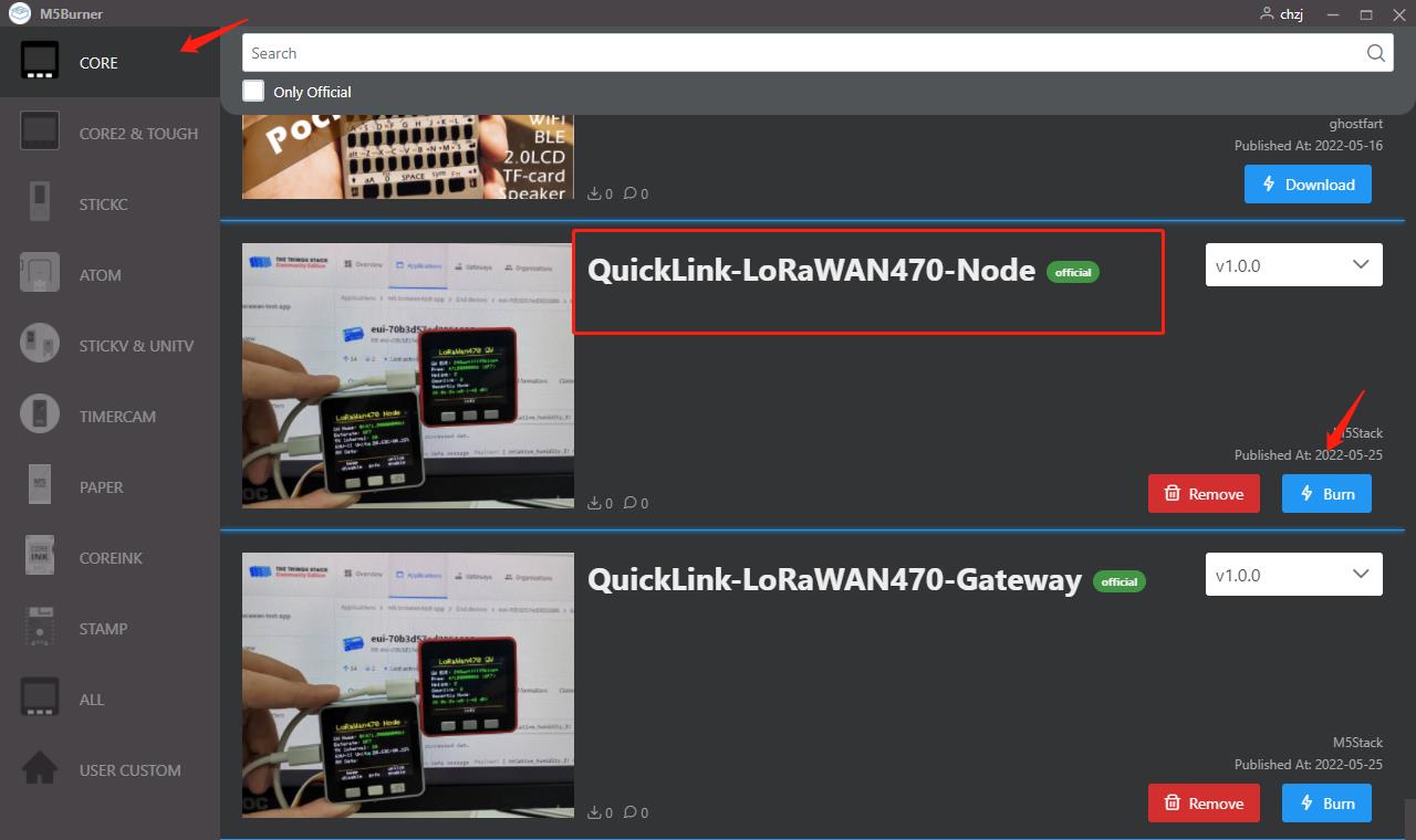
Open the M5burner application to burn the gateway firmware
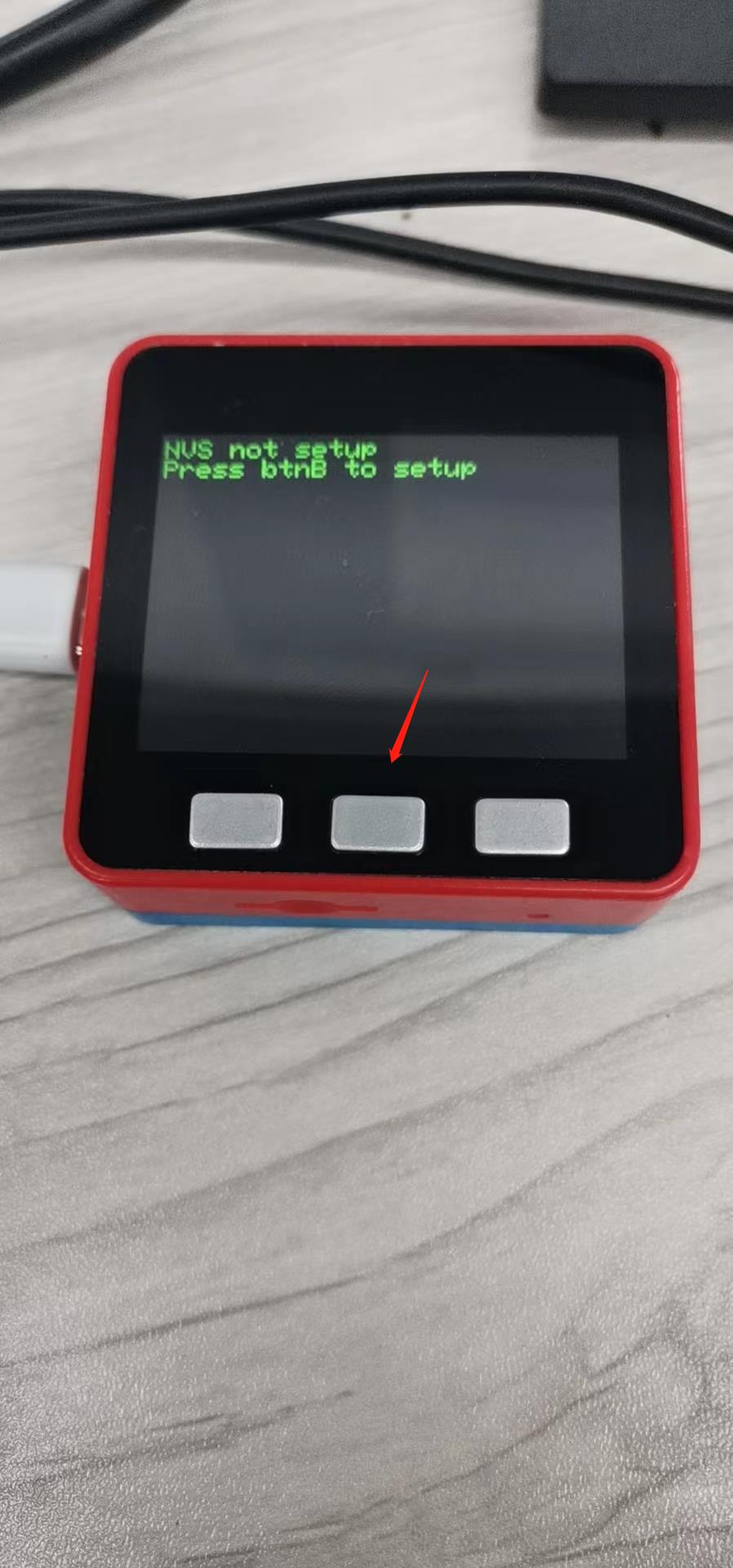
The first time you burn, you will be prompted to enter the M5BurnerNVS setup, at this point we click button B to enter the BurnerNVS setup program.
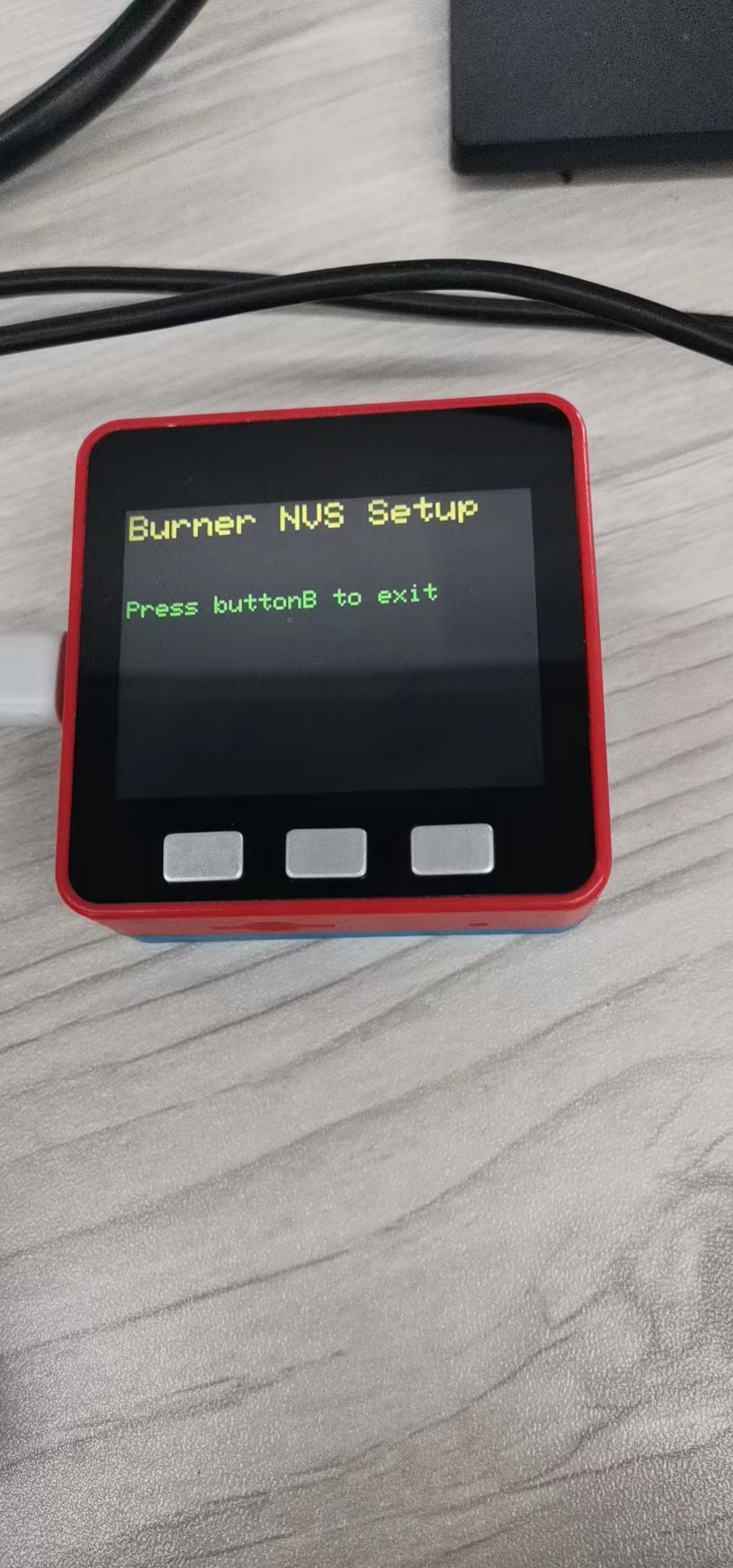
Open M5Burner and enter the BurnerNVS setup screen to make settings

parameters that must be set 1. WIFI_SSID: WIFI SSID 2. WIFI_PASS: WIFI password
Other parameters can be kept as default (Note: the default frequency is 471.9MHz/SF7, the default server is nam1.cloud.thethings.network, and the default time zone is +8)
After completing the setup, we click on the B button of the host computer to reboot the host computer, and then the configuration of the gateway firmware is completed.
2.1.2 Registering a gateway on TTN
First, open the official website of TTN and register an account (Note: For the graphic, you can check our tutorial TTN (The Things Network))
The default server of the gateway is nam1.cloud.thethings.network. The default server is nam1.cloud.thethings.network
Parameters that must be set up
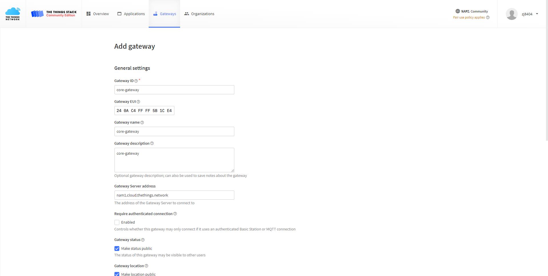
- Gateway ID: human readable string
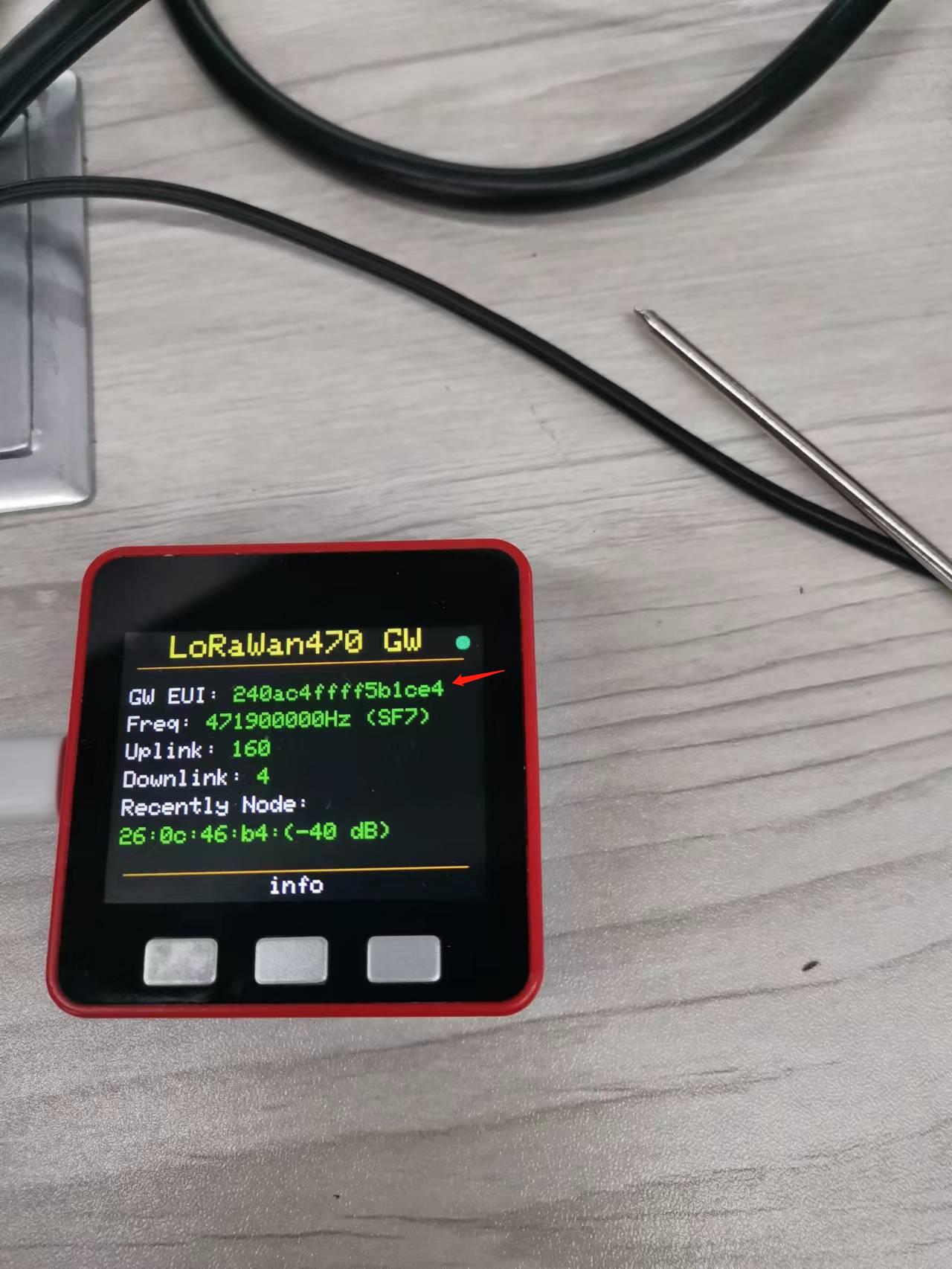
- Gateway EUI: The
GW EUIentry on the host screen, generated based on the MAC address, guarantees global uniqueness.
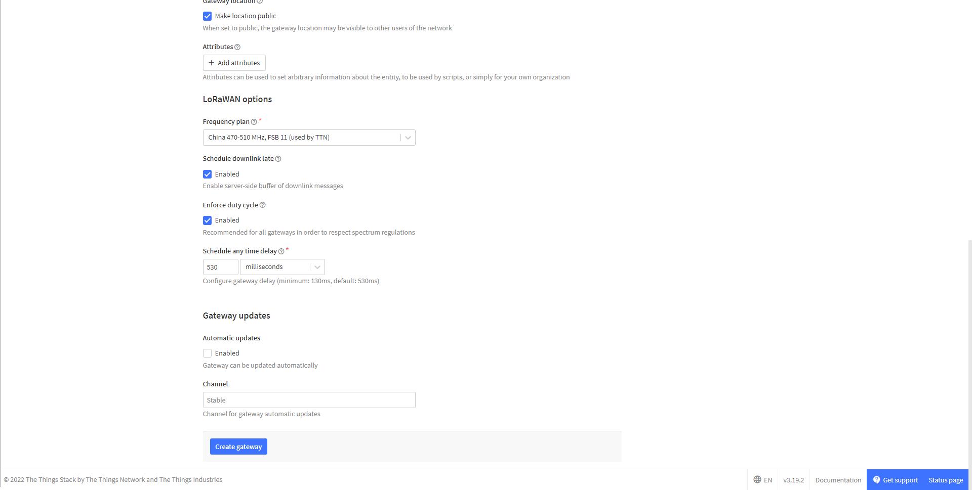
- Schedule downlink late: check for downlink function
- Frequency plan: select China 470-510MHz, FSB11
- Other parameters can be kept as default, so that the gateway is successfully registered on TTN.
2.2 Node
2.2.1 Creating nodes on TTN
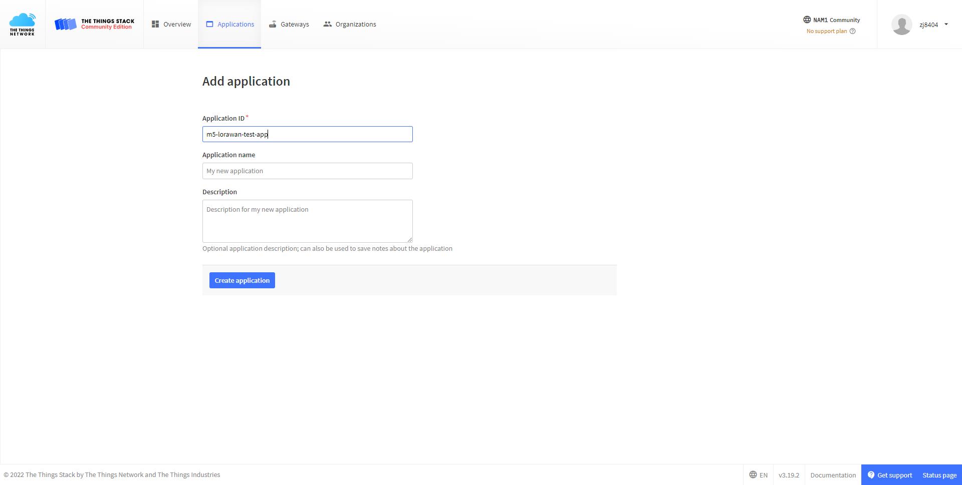
- Creating Applications
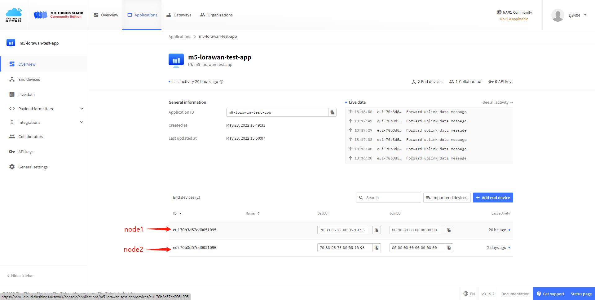
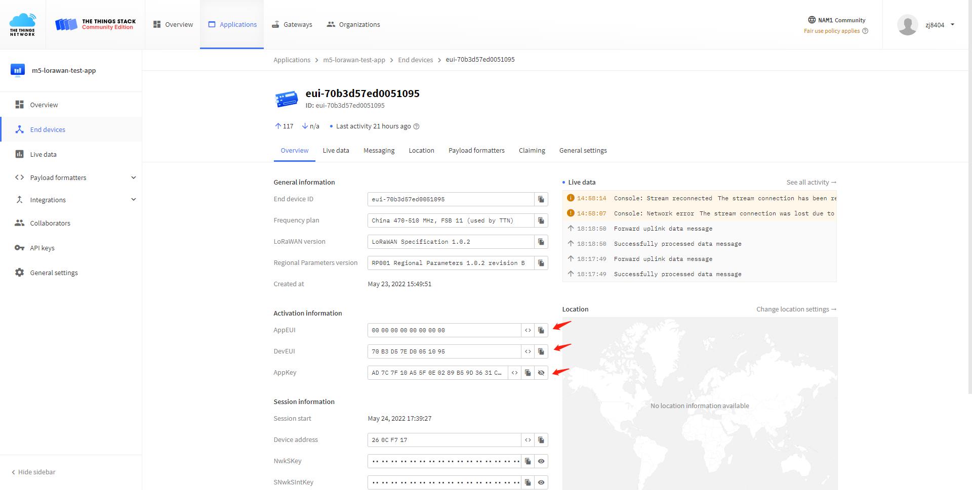
- Create two nodes under this application with the entry type of OTAA and get the DEVEUI, APPEUI and APPKEY of each device (Note: for a graphic you can check our tutorial TTN (The Things Network)
- Mandatory parameters
- Frequency plan: Select China 470-510MHz, FSB11
- LoRaWAN version: LoRaWAN Specifications 1.0.2
- Regional Parameters version: We choose revision B
- The other parameters can be left as default, so the node is successfully created on TTN.
2.2.2 Node firmware burning and configuration
- Open the M5burner application and burn node firmware
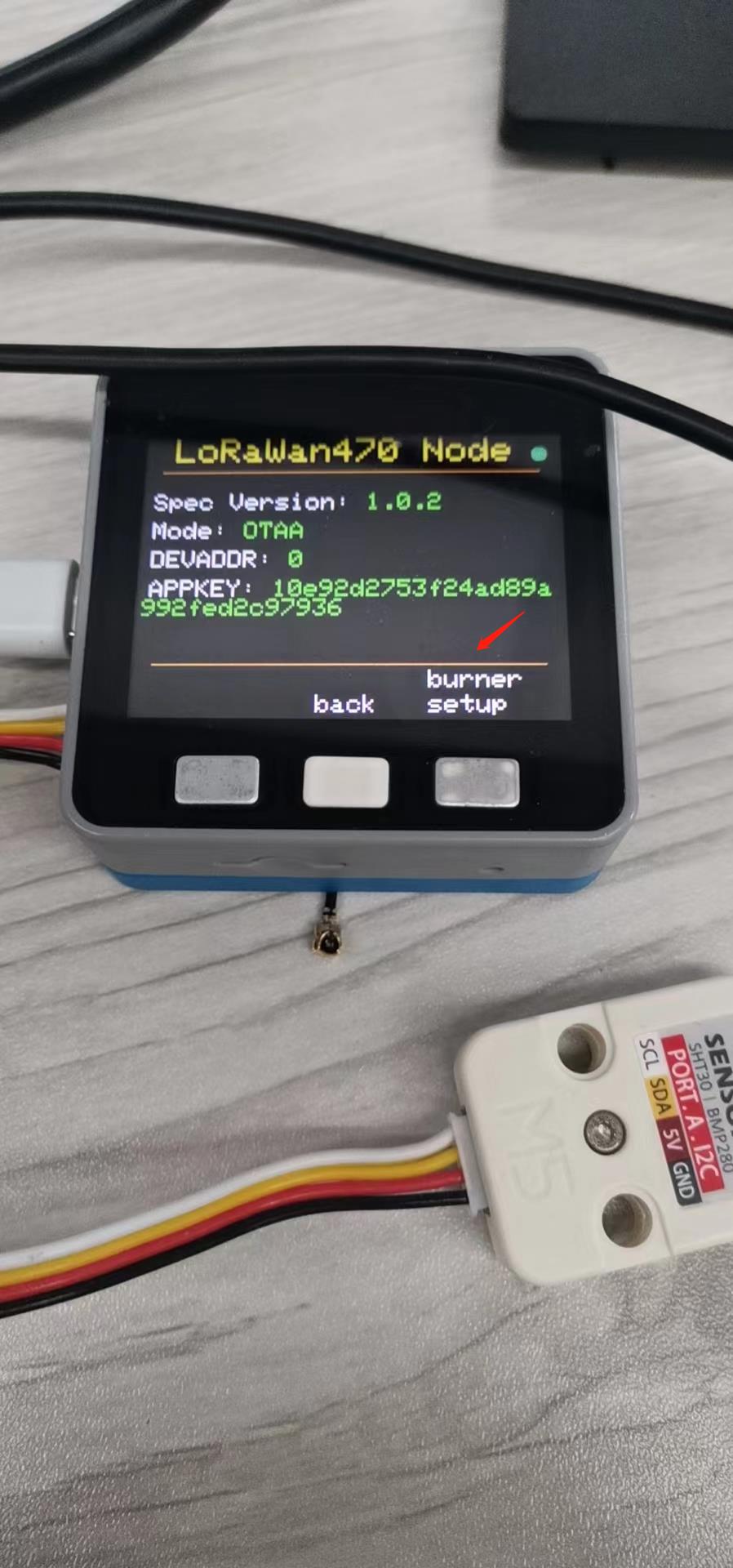
- Click "info"->"burner setup" to enter the BurnerNVS setup program.
- Open M5Burner and enter the BurnerNVS setup screen to make settings
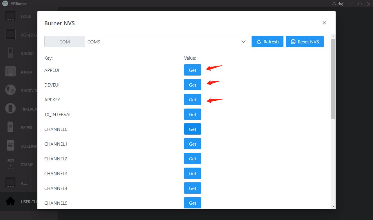
- Parameters that must be set:
- APPEUI: Generated by TTN, available on TTN
- DEVEUI: Generated by TTN, available on TTN
- APPKEY: Generated by TTN, available on TTN
- Other parameters can be kept as default (Note: the default eight channels are 471.9MHz, the top frequency factor SF7, the entry mode OTAA, the sending interval 20s), so the node firmware configuration is complete!
3. Step 3: The node communicates with the TTN
3.1 Uplink
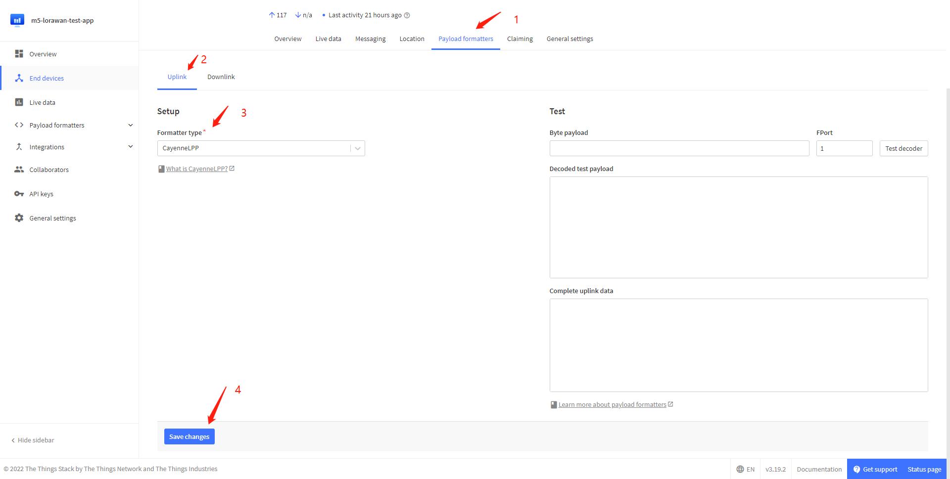
- We used the CayeneLPP library to encapsulate the information, and you need to change the decoding type to CayeneLPP in TTN to see the data uploaded by the node
- After the configuration is completed through the above steps, the node will collect environmental information through the ENV-II Unit and upload it to the TTN at 20s intervals, consistent with the temperature and humidity data displayed on the node
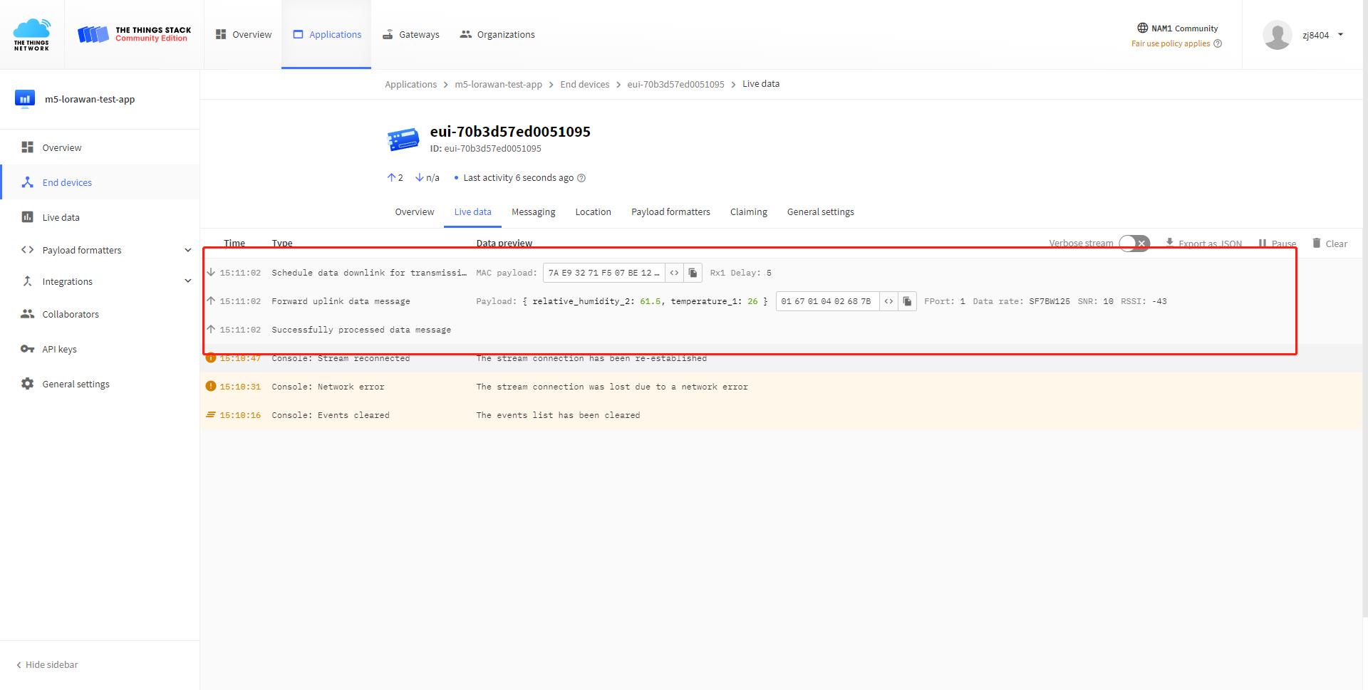
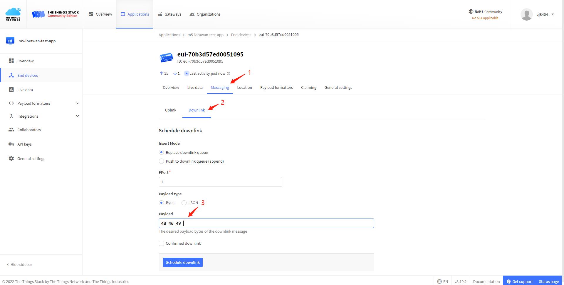
3.2 Downlink
We can add the downlink message to the downlink queue on TTN's website, so that the node receives a Downlink message after the next Uplink upload, and the data displayed on the node is the same as the one set up
4. Step 4: Interface and BurnerNVS Parameter Details
4.1 Gateway
4.1.1 gateway
Start Page.
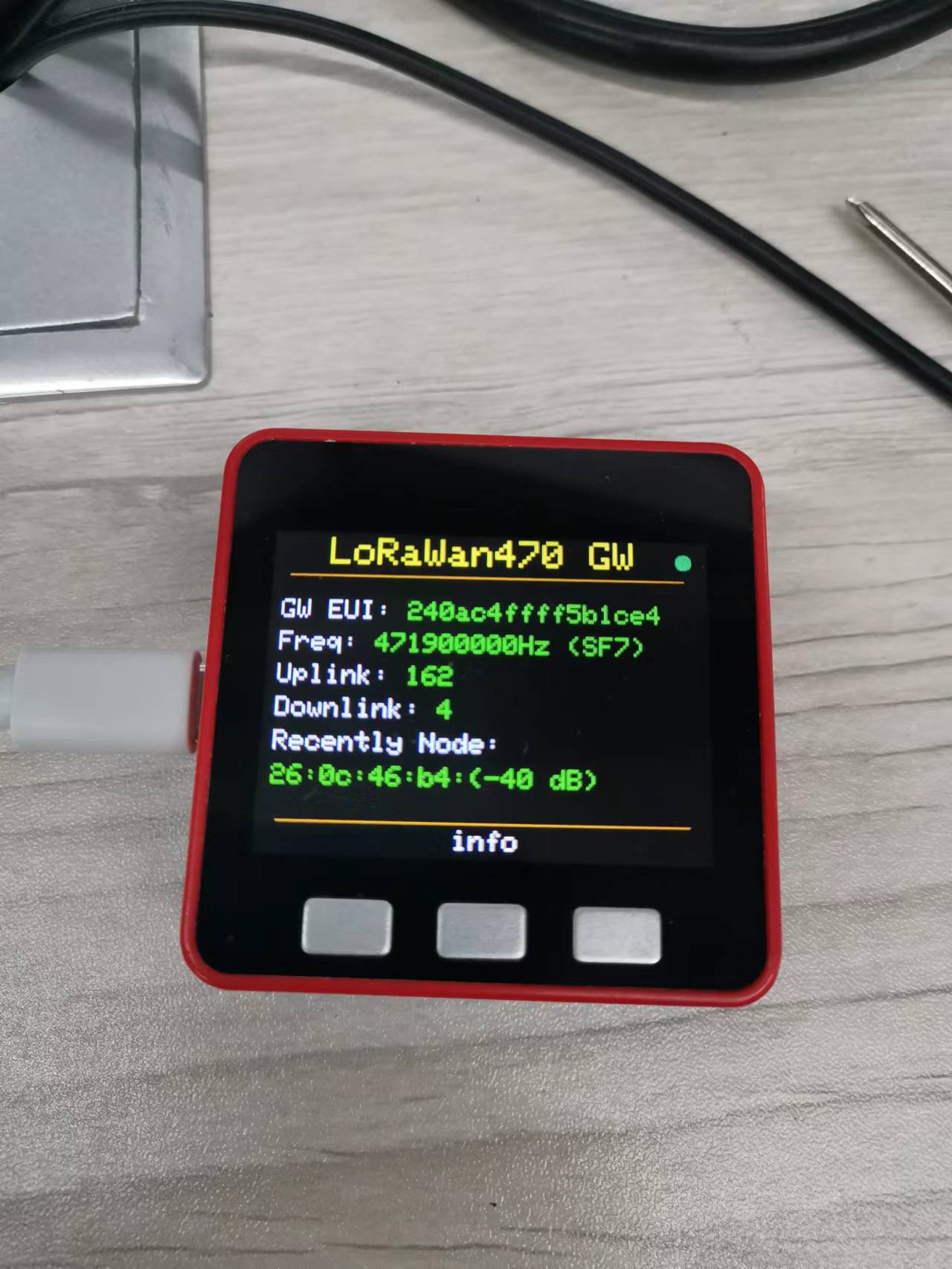
From top to bottom are:
Title bar: LoRaWan470 GW
Status light: blinking green for normal operation, yellow for initialization.
GW EUI: ID unique to each gateway, generated by the MAC address.
Freq: Listening frequency and topology factor
Uplink: the number of LoRa packets uploaded by the gateway
Downlink: The number of LoRa packets downlinked by a gateway
Recently Node: address and RSSI of the most recently communicated node
Press the key:
- info: Allows you to enter the info page.
Key: 1. info: You can enter the info page.
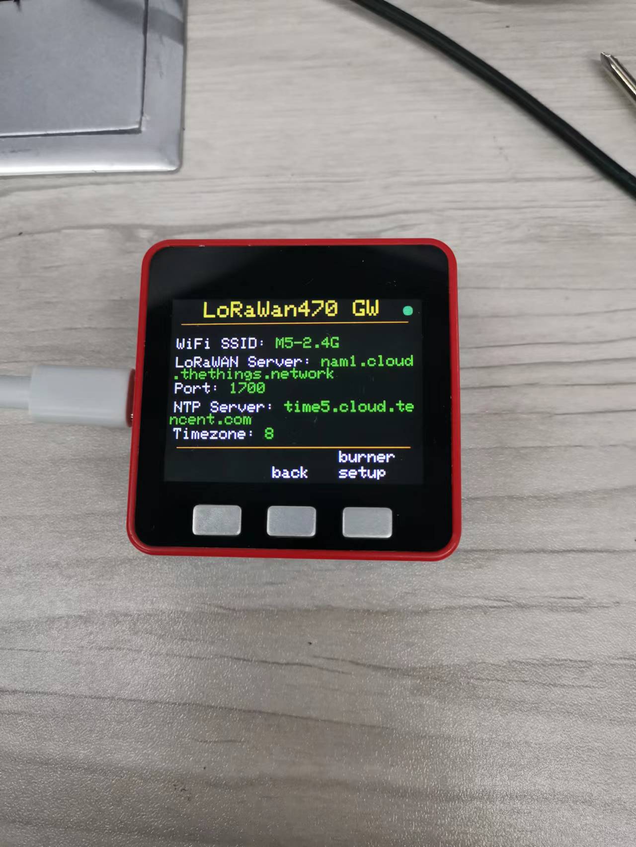
From top to bottom are:
Title bar: LoRaWan470 GW
Status light: blinking green for normal operation, yellow for initialization state
WiFi SSID: WiFi ID
LoRaWAN Server: LoRaWAN server address
Port: LoRaWAN server port
NTP Server: NTP server address
Timezone: Time zone
keys:
back: Returns to the start page.
burner setup: enter BurnerNVS setup program
4.1.2 Gateway BurnerNVS Parameters
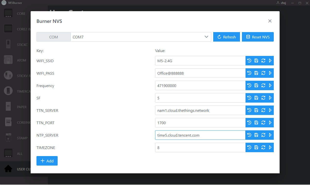
WIFI_SSID: WIFI SSID
WIFI_PASS: WIFI password
Frequency: Listening frequency of the gateway, need to comply with the LoRaWAN protocol, LoRaWAN 470 spectrum range is 470MHz to 510MHz, the specific settings need to check the LoRaWAN protocol, the gateway and the node must be the same frequency.
SF: Frequency Expansion Factor, the range is 5-0, corresponding to SF7 to SF12, the gateway and node must have the same frequency expansion factor.
TTN_SERVER: Address of the LoRaWAN server. 6.
TTN_PORT: Port number of the LoRaWAN server.
NTP_SERVER: Address of NTP server
TIMEZONE: Time zone
4.2 Node
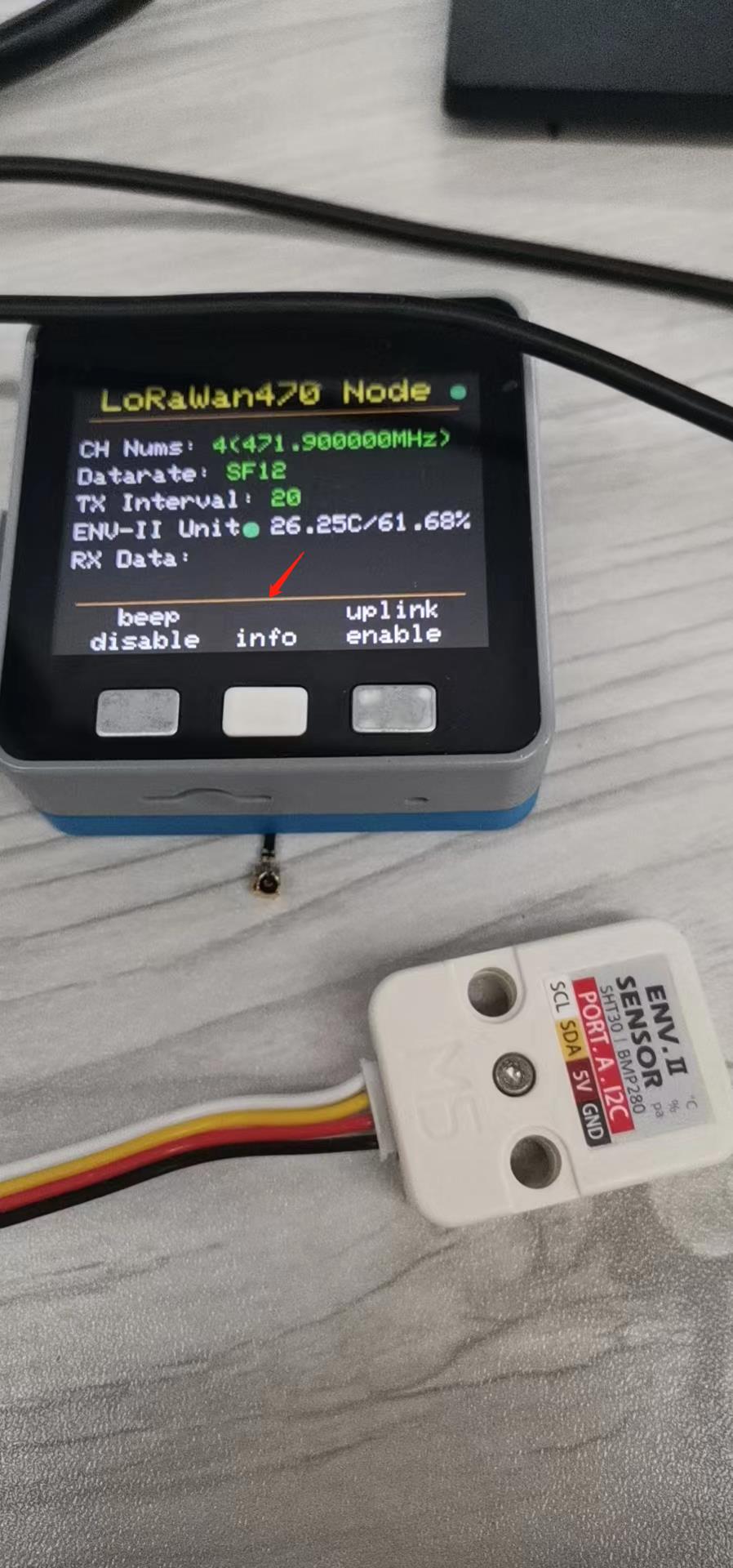
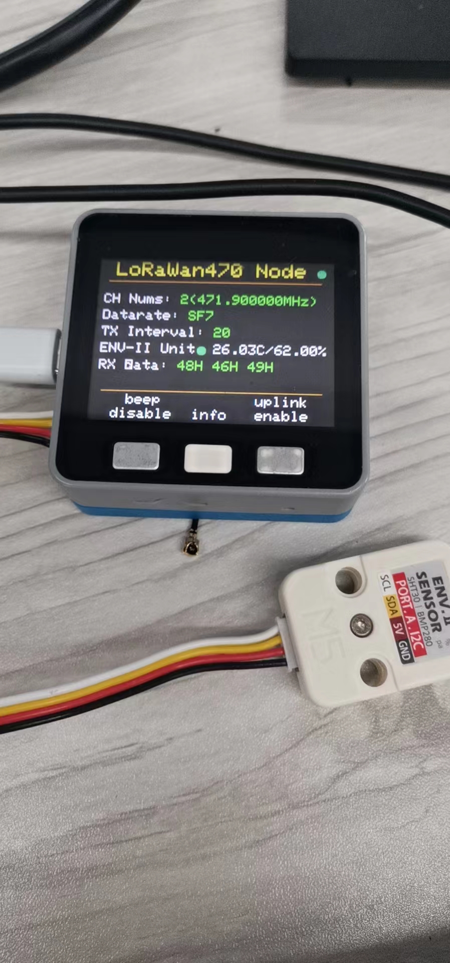
4.2.1 Node Interface
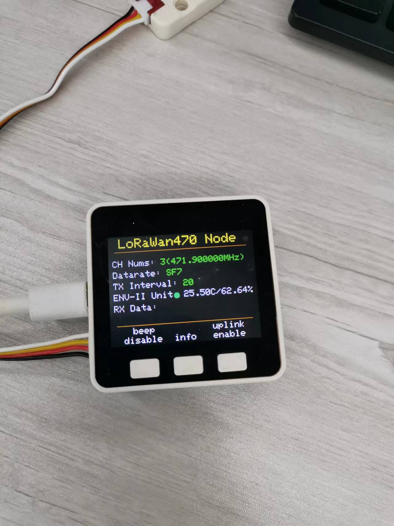
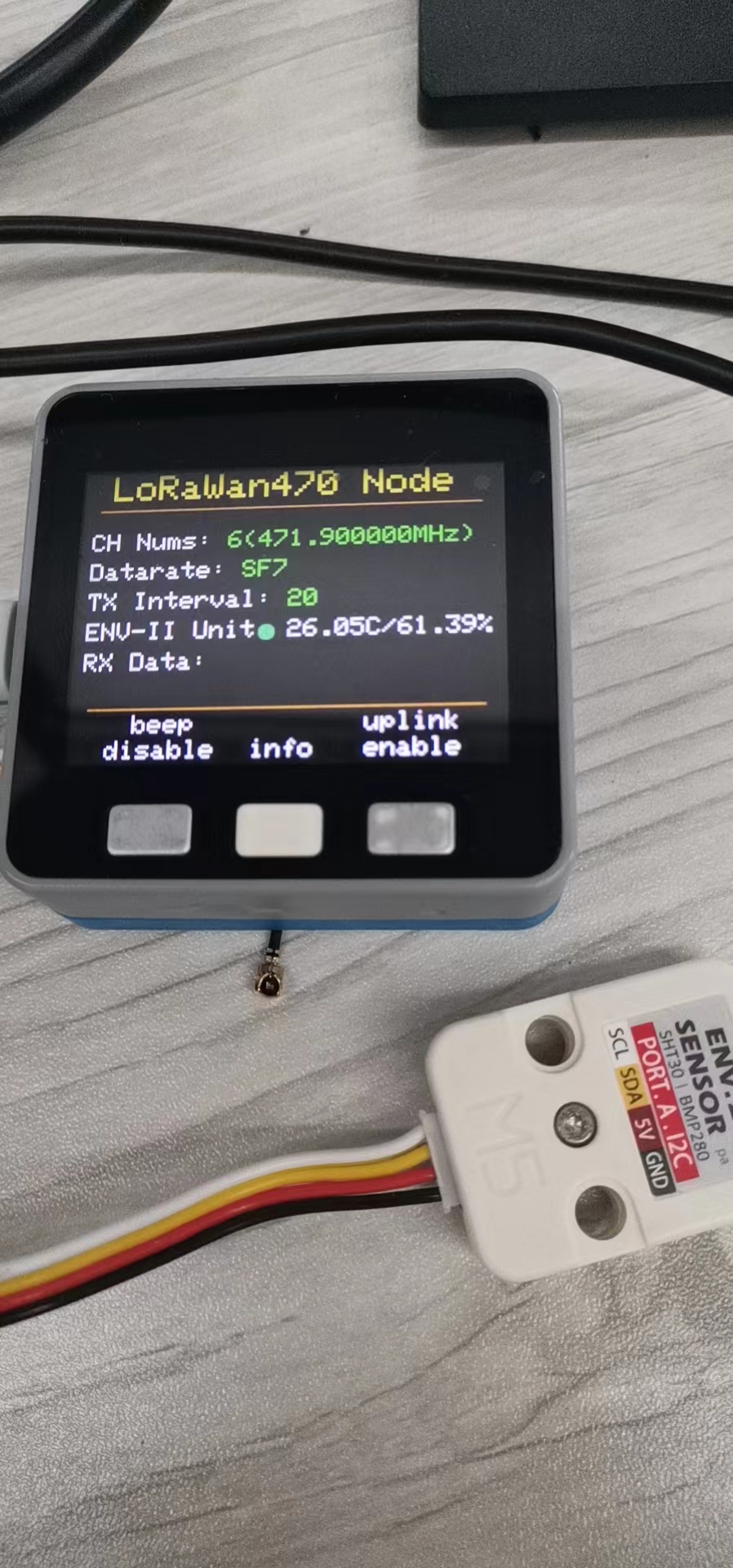
From top to bottom are:
Title bar: LoRaWan470 Node
Status light: blinking green for normal operation, yellow for initialization.
CH Nums: The channel and its corresponding frequency.
TX Interval: Uplink's transmit interval.
ENV-II Unit: The status of ENV-II Unit, green is the normal working status, otherwise it is red, the right side will also show the temperature and humidity.
key:
beep disable means the speaker is off, press this button to switch to beep enable, then if you receive a Downlink message, the speaker will beep once to alert you. 2. info: you can enter the info page, it will show you the time interval of the message.
info: You can enter the info page. 3. uplink enable
uplink enable indicates that Uplink is enabled and the node will upload messages to TTN at 20s interval, press this key to switch to uplink disable.
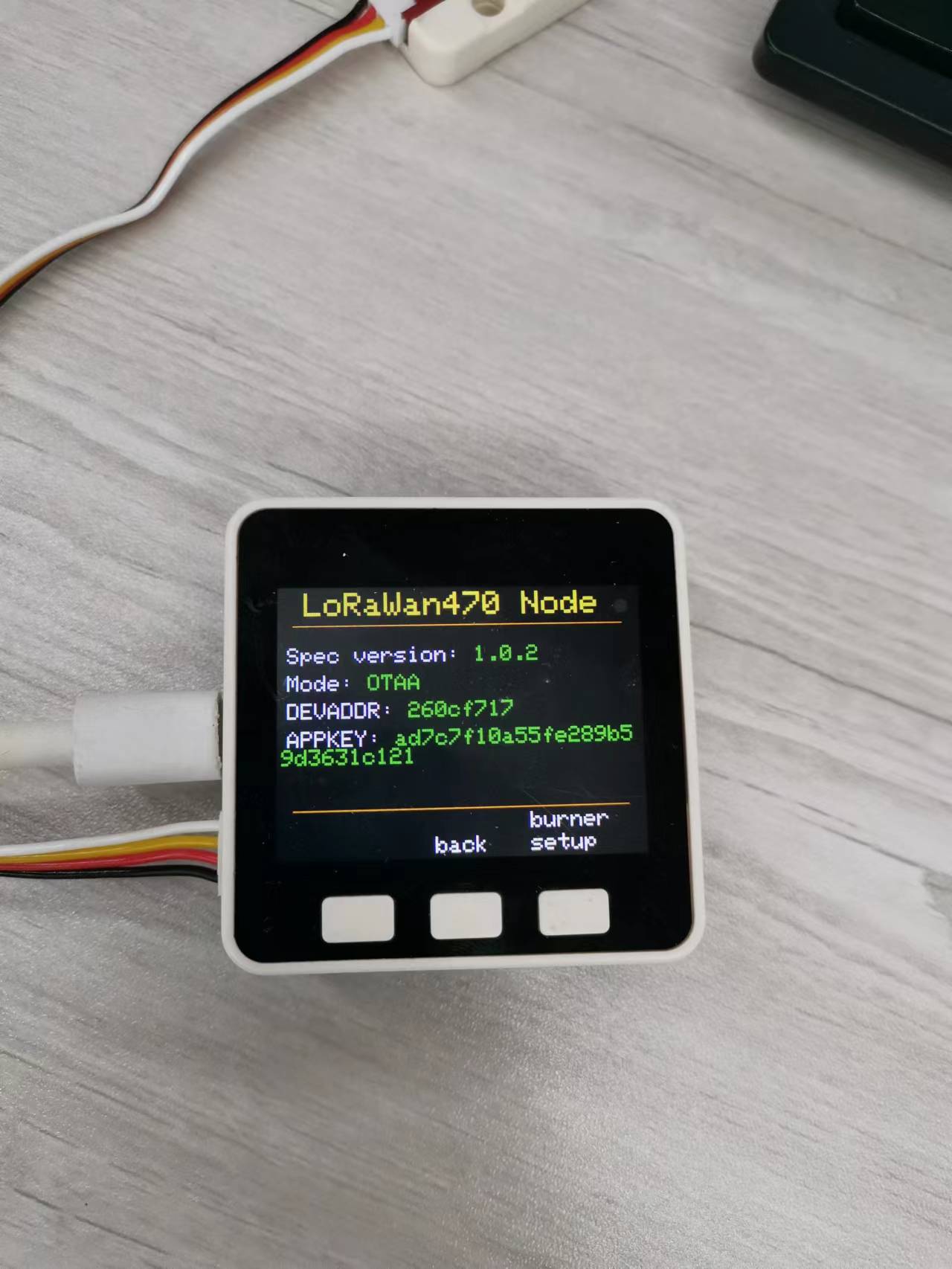
From top to bottom are:
Title bar: LoRaWan470 Node
Status Light: Blinking green for normal operation, yellow for initialization.
Spec Version: This is the LoRaWAN protocol version. 4.
Mode: Mode of entry, now it is OTAA. 5.
DEVADDR: Device address
keys:
- back: Return to the start page.
- burner setup: Enter the BurnerNVS setup program.
4.2.2 Node BurnerNVS Parameters
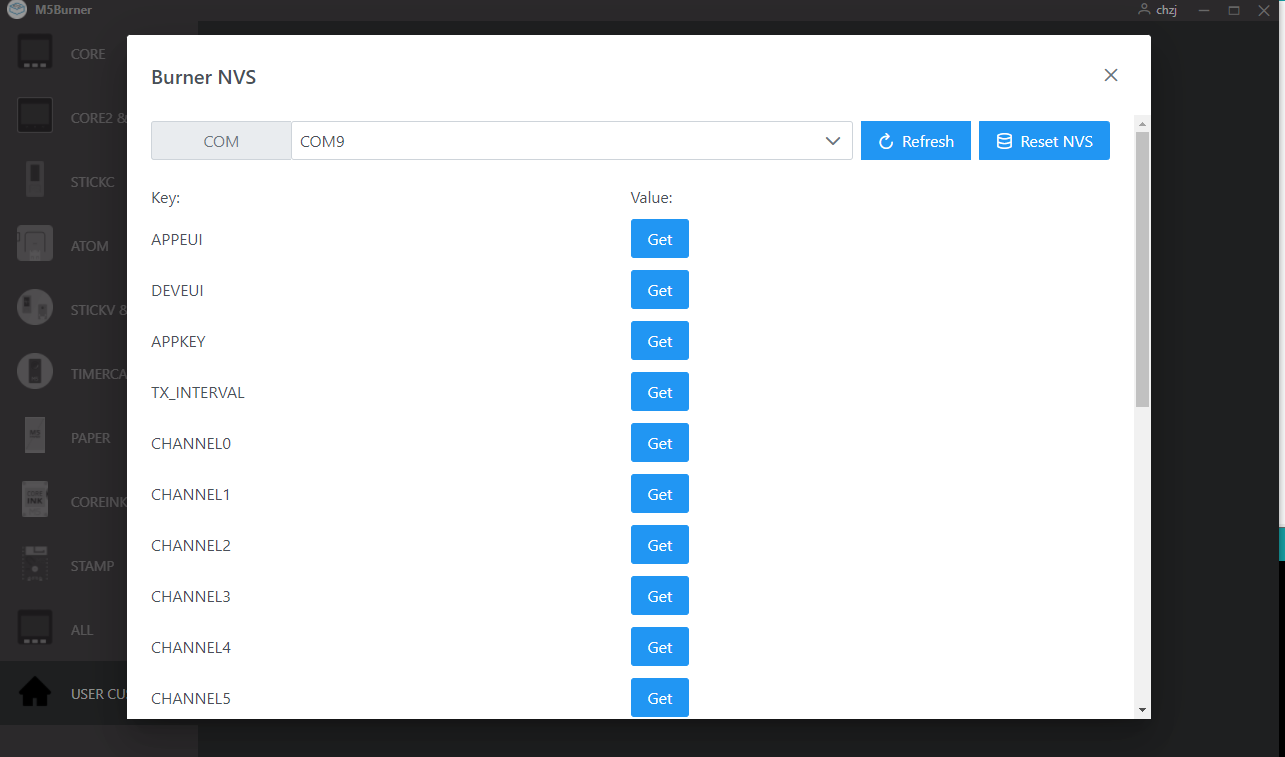
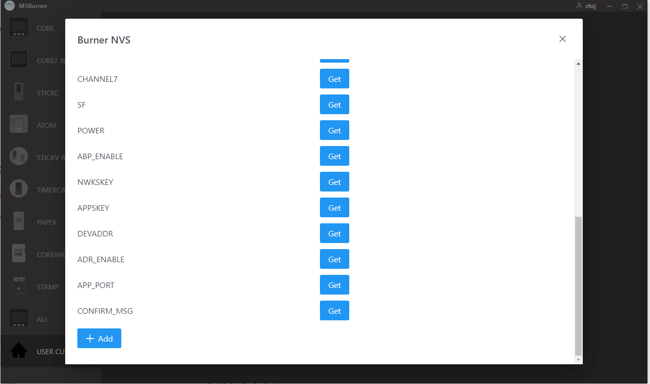
APPEUI & DEVEUI & APPKEY: OTAA entry parameters, generated by TTN
TX_INTERVAL: time interval of uplink
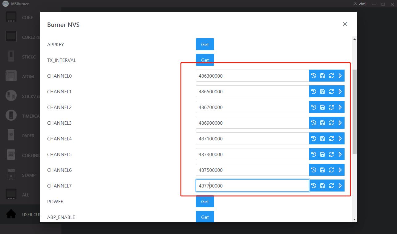
CHANNEL0 ~ CHANNEL8: frequency of each channel, need to comply with the LoRaWAN protocol, LoRaWAN 470 spectrum range is 470MHz to 510MHz, specific settings need to check the LoRaWAN protocol, the frequency of the gateway and the node must be the same.
SF: Frequency Expansion Factor, the range is 5-0, corresponding to SF7 to SF12, the gateway and node must have the same frequency expansion factor.
POWER: Transmit power, the range is 0-20, the higher the value the higher the power, the default is 20.
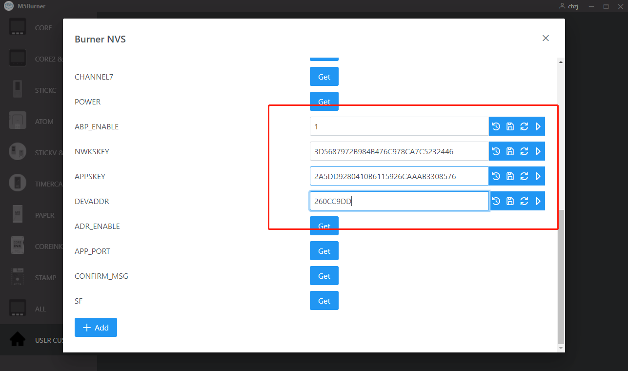
ABP_ENABLE: ABP Access Mode Enable, 1 is enable, 0 is disable. 1 is on, 0 is off. 0 means OTAA access mode, the setting related to ABP is invalid. If it is 1, it is ABP access mode, and the settings related to OTAA are invalid.
NWKSKEY & APPSKEY & DEVADDR: Parameters for ABP access, can be generated by TTN. 8. ADR_ENABLE: The parameters for ABP access.
ADR_ENABLE: ADR enable, 1 is on, 0 is off. 9.
APP_PORT: Sets the application port, range is 1-255.
CONFIRM_MSG: Confirmation message enable, 1 is on, 0 is off. 1 is on, 0 is off. If it is on, you will receive an ACK after each uplink.
5. Step 5: Other applications
5.1 Enter the BurnerNVS program in Run
Click info -> burner setup
You will then be taken to the following page, indicating that you have entered the Burner NVS setup program
At this point we can open the Burner application to set up BurnerNVS
5.2 Nodes connect to other gateways
When we need to connect to other gateways, we only need to modify the frequency of CHANNEL0 - CHANNEL8
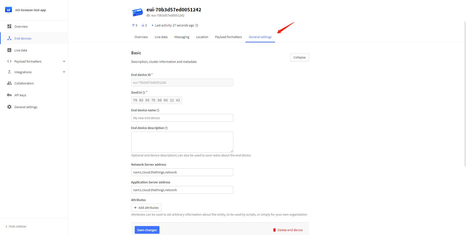
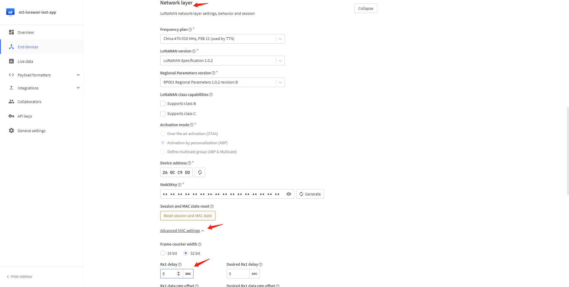
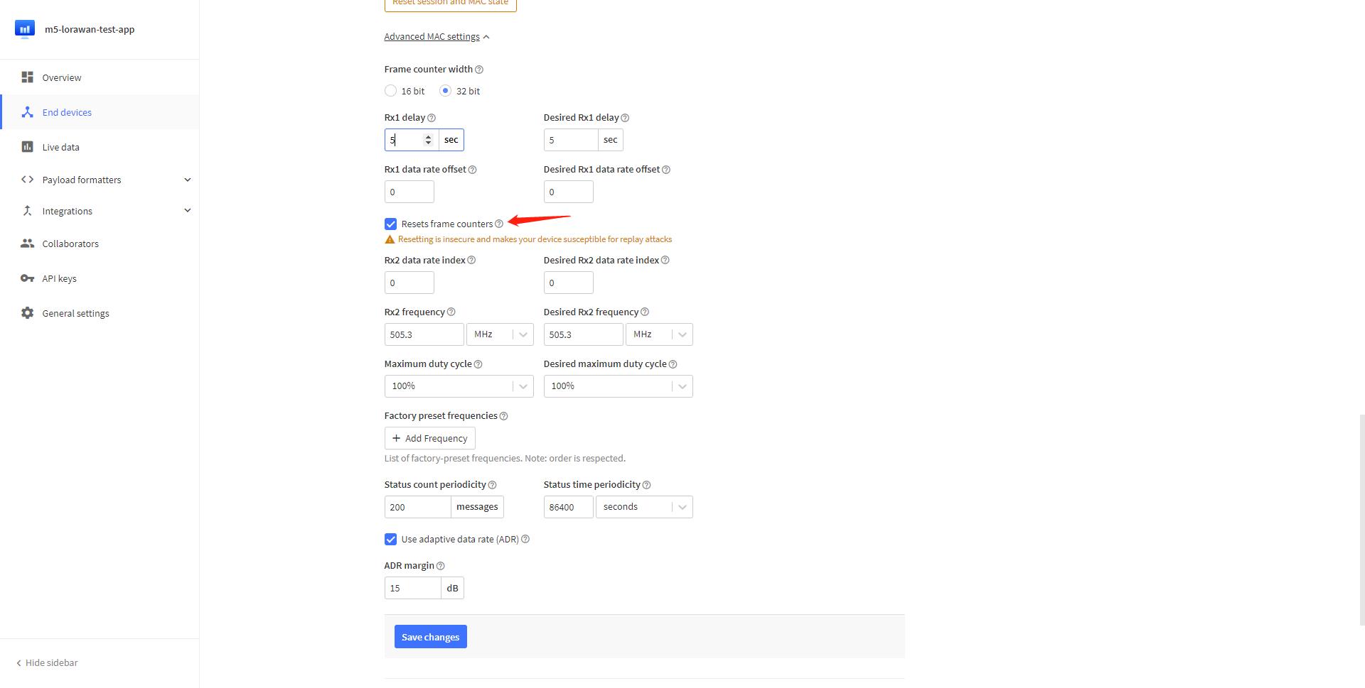
5.3 Nodes use ABP mode for network entry
If we need to use ABP mode for network access, we just need to turn on ABP_ENABLE to enable it.
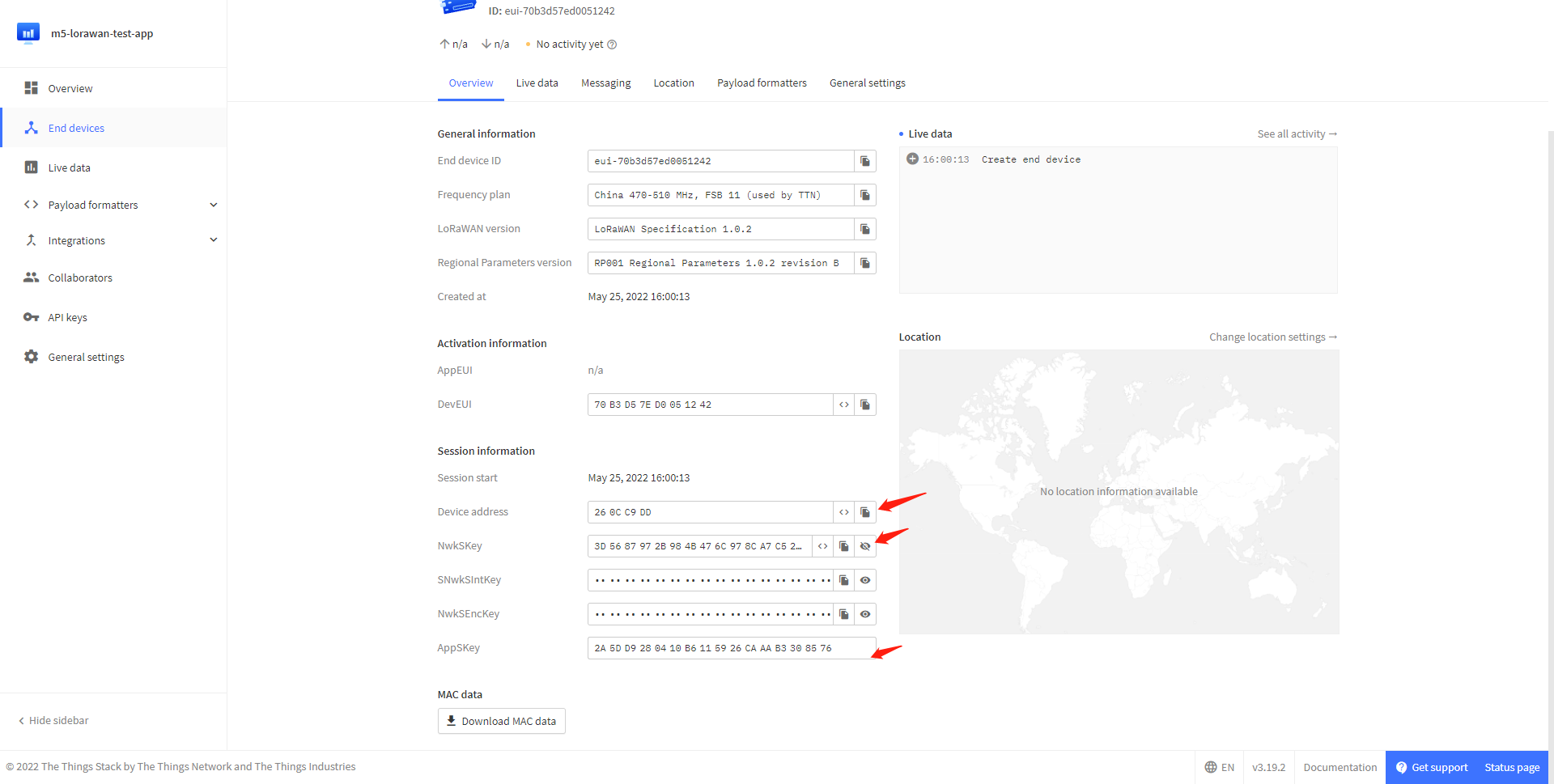
Resets frame counters option under General settings -> Network layer -> Advanced MAC settings in the TTN ABP node management page.