

Product Guide
Linux PC
CardputerZero
AI Accelerator Card
LLM-8850 Card
Large Language Models
AI & Agent
Real-Time AI Voice Assistant
XiaoZhi Voice Assistant
AtomS3R-M12 Volcengine Kit
Offline Voice Recognition
Industrial Control
IoT Measuring Instruments
Air Quality
PowerHub
Module13.2 PPS
VAMeter
T-Lite
Input & Output Devices
Ethernet Camera
PoECAM
Wi-Fi Camera
Unit CamS3/-5MP
AI Camera
LoRa & LoRaWAN
Motor Control
Restore Factory Firmware
DIP Switch Usage Guide
M5StickV MaixPy Getting Started Guide
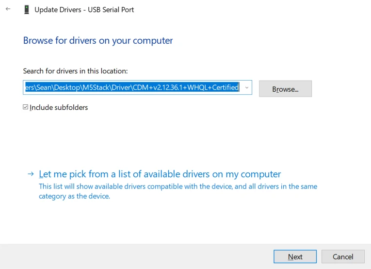
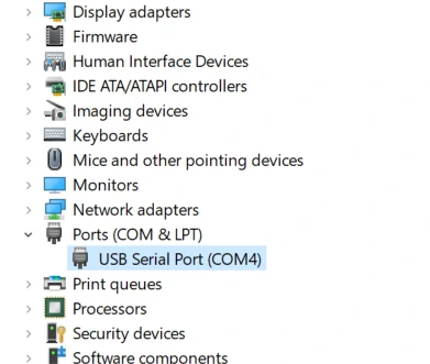
Driver installation
M5Stack or USB Serial. For Windows users, we recommend to install it through Windows Device Manager using the .zip file, because the executable file installation method may not work properly).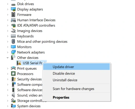
System Settings - > Privacy & Security - > Allow applications from - > Anywhere before the installation.Firmware burning
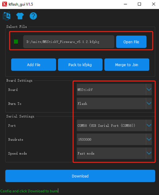
Kflash_GUI
- Download the firmware and Kflash_GUI burning tool (UnitV is using the same firmware as StickV).
| Firmware version | Download link |
|---|---|
| M5StickV_Firmware_v5.1.2.kfpkg | Download |
| Software version | Download link |
|---|---|
| Kflash_GUI_Windows | Download |
| Kflash_GUI_MacOS | Download |
| Kflash_GUI_Linux | Download |
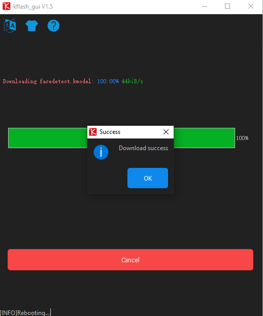
- Connect the device to the computer, open the Kflash_GUI, select the correct device port, choose board type M5StickV, firmware file, baud rate, and click Download to start burning.
MaixPy IDE
MaixPy IDE can edit/run programs, see the camera frames and transfer files easily. It's a very easy-to-use software for beginners and those want to develop the project quick and easily.
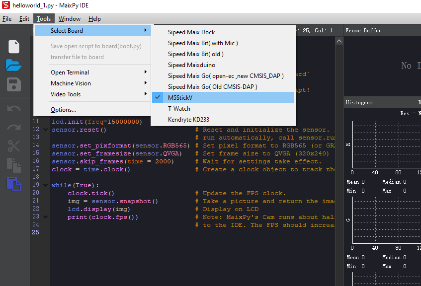
Run MaixPy IDE, click on the toolbar and select the device type. Tools-> Select Board-> M5StickV
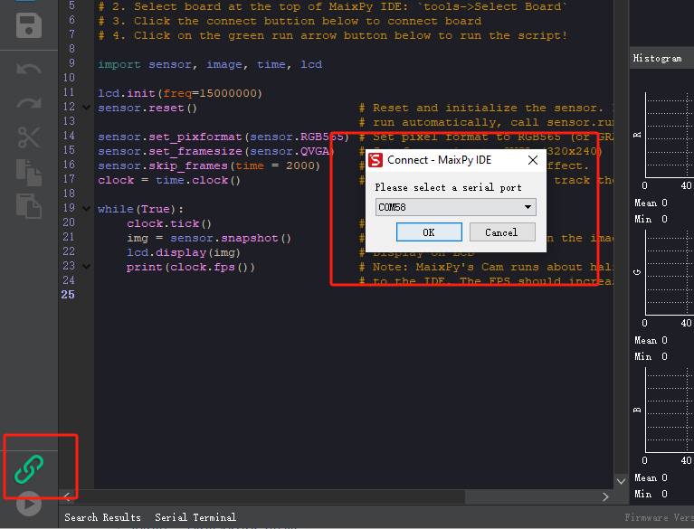
Click the Connect button in the lower left corner and select the correct connection port, click OK.
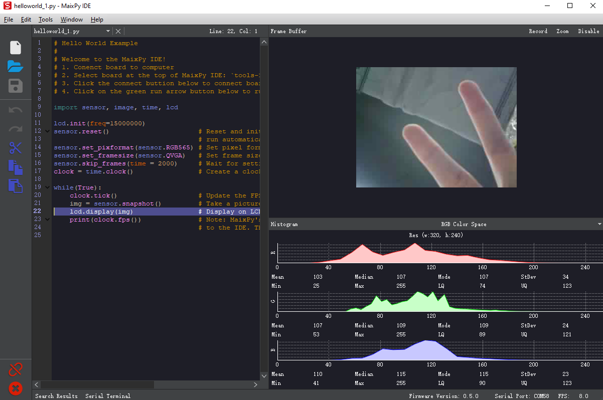
The connection button will turn into red when connection succeed. Now you can edit your codes and run them by clicking the Run button at the lower left corner.
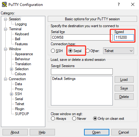
Serial debugging
- USB connection for UnitV will be enabled as system log port by default. Users can use this interface to connect UnitV to the computer using any serial tools, and the default baud rate is
115200bps. The following operation is based on Putty.
- After running Putty, connect the UnitV to the computer, set the port number and baud rate, then click "open" to start the connection.
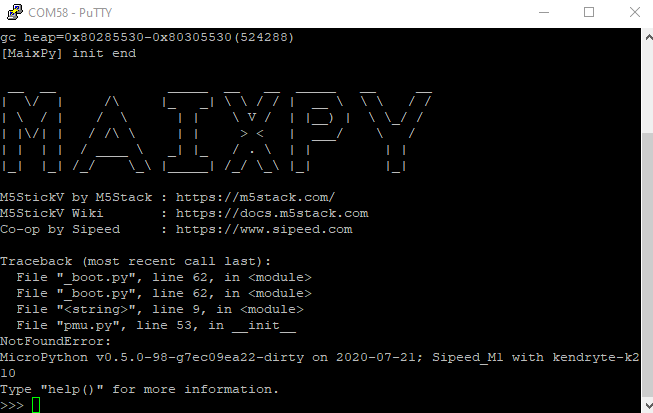
- You will automatically enter the interactive interface of MaixPy after connection succeed. The device will run factory program by default, you can interrupt it by pressing the shortcut key "Ctrl+C".
Editing programs
In MaixPy firmware, there is a built-in open-source editor Micropython Editor(pye), which makes it easy to modify program files.
You can use os.listdir() to list the files in the current directory.
Use pye("hello.py") to create a file and enter editing mode.
After finishing editing, press Ctrl+S > Enter to save, press Ctrl+Q to exit the editor.
Note: You will need to use key Del for backspace, the key Backspace will trigger Ctrl+H by default.
Run the program
Use os.chdir() to switch from the current directory to the file directory, e.g. os.chdir("/flash").
Method 1: Run the codes line by line
Run import hello, then you can see the output hello maixpy.
Please note that import can only execute at once. If you need to execute it more than once, it is recommended to run the .py file as following:
Method 2: Run the .py file
with open("hello.py") as f:
    exec(f.read())
Auto-run programs on boot
The system will create a boot.py file in the /flash or /sd directory. System will run this file while booting.
MaixPy IDE
MaixPy IDE allows you to easily edit, upload and execute scripts in real time, as well as monitor camera images and transfer files in real time. The performance of MaixPy IDE will be reduced due to the resources required for data compression and transfer, but it is a good tool for developers who do not have demanding performance needs or are in the debugging phase.
Windows platform can directly double-click the exe file, run the installation program.
Linux command line to run permissions and then, execute the command
chmod +x maixpy-ide-linux-x86_64-0.2.2.run
./maixpy-ide-linux-x86_64-0.2.2.run
Run MaixPy IDE, click on the toolbar and select the board model. Tool-> Select Board-> M5StickV (Tools->Select Board)
Click the Connect button in the lower left corner and select the correct connection port, click OK.
When the connection button changes from green to red, it means that the connection has been successful, you can edit the code in the upper edit box, click on the run button in the lower left corner to execute the code, for verification.
Video Tutorial
WS2812
The firmware includes a built-in WS2812 RGB LED driver library. Below is a reference example:
from modules import ws2812
from fpioa_manager import *
fm.register(board_info.CONNEXT_A)
class_ws2812 = ws2812(board_info.CONNEXT_A,130)
r=0
dir = True
while True:
    if dir:
        r += 1
    else:
        r -= 1
    if r>=255:
        r = 255
        dir = False
    elif r<0:
        r = 0
        dir = True
    for i in range(130):
        a = class_ws2812.set_led(i,(0,0,r))
a=class_ws2812.display()PMU
Description: Use this API to implement short press reset, long press sleep. Pass in True or False, True to start button detection, False to cancel detection.
from pmu import axp192
pmu = axp192()
pmu.enablePMICSleepMode(True)
Maixpy Example Programs
Quoted from: https://github.com/anoken/purin\_wo\_motto\_mimamoru\_gijutsu/tree/master/03\_maixpy\_example
Button
example
import lcd
from Maix import I2S, GPIO
from fpioa_manager import fm
from board import board_info

lcd.init()
fm.register(board_info.BUTTON_A, fm.fpioa.GPIO1)
but_a=GPIO(GPIO.GPIO1, GPIO.IN, GPIO.PULL_UP)

fm.register(board_info.BUTTON_B, fm.fpioa.GPIO2)
but_b = GPIO(GPIO.GPIO2, GPIO.IN, GPIO.PULL_UP)

but_a_pressed = 0
but_b_pressed = 0

while(True):
    if but_a.value() == 0 and but_a_pressed == 0:
        print("A_push")
        but_a_pressed=1
    if but_a.value() == 1 and but_a_pressed == 1:
        print("A_release")
        but_a_pressed=0

    if but_b.value() == 0 and but_b_pressed == 0:
        print("B_push")
        but_b_pressed=1
    if but_b.value() == 1 and but_b_pressed == 1:
        print("B_release")
but_b_pressed=0LED
example
from fpioa_manager import *
from Maix import GPIO
from board import board_info

fm.register(board_info.BUTTON_A, fm.fpioa.GPIO1)
but_a=GPIO(GPIO.GPIO1, GPIO.IN, GPIO.PULL_UP)

fm.register(board_info.BUTTON_B, fm.fpioa.GPIO2)
but_b = GPIO(GPIO.GPIO2, GPIO.IN, GPIO.PULL_UP)

fm.register(board_info.LED_W, fm.fpioa.GPIO3)
led_w = GPIO(GPIO.GPIO3, GPIO.OUT)
led_w.value(1) # LED is Active Low

fm.register(board_info.LED_R, fm.fpioa.GPIO4)
led_r = GPIO(GPIO.GPIO4, GPIO.OUT)
led_r.value(1) # LED is Active Low

fm.register(board_info.LED_G, fm.fpioa.GPIO5)
led_g = GPIO(GPIO.GPIO5, GPIO.OUT)
led_g.value(1) # LED is Active Low

fm.register(board_info.LED_B, fm.fpioa.GPIO6)
led_b = GPIO(GPIO.GPIO6, GPIO.OUT)
led_b.value(1) # LED is Active Low

lcd.init()
while(True):
    if but_a.value() == 0:
        led_w.value(0)
        led_r.value(1)
        led_g.value(1)
        led_b.value(1)

    elif but_b.value()== 0:
        led_w.value(1)


### LED

**example**
```python

from fpioa_manager import *
from Maix import GPIO
from board import board_info

fm.register(board_info.BUTTON_A, fm.fpioa.GPIO1)
but_a=GPIO(GPIO.GPIO1, GPIO.IN, GPIO.PULL_UP)

fm.register(board_info.BUTTON_B, fm.fpioa.GPIO2)
but_b = GPIO(GPIO.GPIO2, GPIO.IN, GPIO.PULL_UP)

fm.register(board_info.LED_W, fm.fpioa.GPIO3)
led_w = GPIO(GPIO.GPIO3, GPIO.OUT)
led_w.value(1) # LED is Active Low

fm.register(board_info.LED_R, fm.fpioa.GPIO4)
led_r = GPIO(GPIO.GPIO4, GPIO.OUT)
led_r.value(1) # LED is Active Low

fm.register(board_info.LED_G, fm.fpioa.GPIO5)
led_g = GPIO(GPIO.GPIO5, GPIO.OUT)
led_g.value(1) # LED is Active Low

fm.register(board_info.LED_B, fm.fpioa.GPIO6)
led_b = GPIO(GPIO.GPIO6, GPIO.OUT)
led_b.value(1) # LED is Active Low

lcd.init()
while(True):
    if but_a.value() == 0:
        led_w.value(0)
        led_r.value(1)
        led_g.value(1)
        led_b.value(1)

    elif but_b.value()== 0:
        led_w.value(1)
        led_r.value(0)
        led_g.value(1)
        led_b.value(1)

    else:
        led_w.value(1)
        led_r.value(1)
        led_g.value(1)
led_b.value(1)PWM
example
import time,math
from machine import Timer,PWM
from fpioa_manager import fm
from board import board_info

tim = Timer(Timer.TIMER0, Timer.CHANNEL0, mode=Timer.MODE_PWM)
PWM_ch = PWM(tim, freq=500000, duty=0, pin=board_info.LED_W)
cnt=0
while(True):
    duty_val=math.fabs(math.sin(cnt))*100
    PWM_ch.duty(duty_val)
    cnt=cnt+0.01
time.sleep_ms(10)I2C scan
example
from machine import I2C
i2c = I2C(I2C.I2C0, freq=100000, scl=28, sda=29)
devices = i2c.scan()
print(devices)MPU6886
example
from machine import I2C
import lcd
MPU6886_ADDRESS=0x68
MPU6886_WHOAMI=0x75
MPU6886_ACCEL_INTEL_CTRL=  0x69
MPU6886_SMPLRT_DIV=0x19
MPU6886_INT_PIN_CFG=   0x37
MPU6886_INT_ENABLE=0x38
MPU6886_ACCEL_XOUT_H=  0x3B
MPU6886_TEMP_OUT_H=0x41
MPU6886_GYRO_XOUT_H=   0x43
MPU6886_USER_CTRL= 0x6A
MPU6886_PWR_MGMT_1=0x6B
MPU6886_PWR_MGMT_2=0x6C
MPU6886_CONFIG=0x1A
MPU6886_GYRO_CONFIG=   0x1B
MPU6886_ACCEL_CONFIG=  0x1C
MPU6886_ACCEL_CONFIG2= 0x1D
MPU6886_FIFO_EN=   0x23

i2c = I2C(I2C.I2C0, freq=100000, scl=28, sda=29)
devices = i2c.scan()
time.sleep_ms(10)
print("i2c",devices)

def write_i2c(address, value):
    i2c.writeto_mem(MPU6886_ADDRESS, address, bytearray([value]))
    time.sleep_ms(10)

def MPU6866_init():
    write_i2c(MPU6886_PWR_MGMT_1, 0x00)
    write_i2c(MPU6886_PWR_MGMT_1, 0x01<<7)
    write_i2c(MPU6886_PWR_MGMT_1,0x01<<0)
    write_i2c(MPU6886_ACCEL_CONFIG,0x10)
    write_i2c(MPU6886_GYRO_CONFIG,0x18)
    write_i2c(MPU6886_CONFIG,0x01)
    write_i2c(MPU6886_SMPLRT_DIV,0x05)
    write_i2c(MPU6886_INT_ENABLE,0x00)
    write_i2c(MPU6886_ACCEL_CONFIG2,0x00)
    write_i2c(MPU6886_USER_CTRL,0x00)
    write_i2c(MPU6886_FIFO_EN,0x00)
    write_i2c(MPU6886_INT_PIN_CFG,0x22)
    write_i2c(MPU6886_INT_ENABLE,0x01)

def MPU6866_read():
    accel = i2c.readfrom_mem(MPU6886_ADDRESS, MPU6886_ACCEL_XOUT_H, 6)
    accel_x = (accel[0]<<8|accel[1])
    accel_y = (accel[2]<<8|accel[3])
    accel_z = (accel[4]<<8|accel[5])
    if accel_x>32768:
        accel_x=accel_x-65536
    if accel_y>32768:
        accel_y=accel_y-65536
    if accel_z>32768:
        accel_z=accel_z-65536
    return accel_x,accel_y,accel_z

MPU6866_init()
lcd.init()
lcd.clear()
aRes = 8.0/32768.0;
while True:
    x,y,z=MPU6866_read()
    accel_array = [x*aRes, y*aRes, z*aRes]
    print(accel_array);
    lcd.draw_string(20,50,"x:"+str(accel_array[0]))
    lcd.draw_string(20,70,"y:"+str(accel_array[1]))
    lcd.draw_string(20,90,"z:"+str(accel_array[2]))
time.sleep_ms(10)SH200Q
example
from machine import I2C
import lcd

i2c = I2C(I2C.I2C0, freq=100000, scl=28, sda=29)
devices = i2c.scan()
print("i2c",devices)

SH200I_ADDRESS=108
SH200I_WHOAMI= 0x30
SH200I_ACC_CONFIG= 0x0E
SH200I_GYRO_CONFIG= 0x0F
SH200I_GYRO_DLPF= 0x11
SH200I_FIFO_CONFIG= 0x12
SH200I_ACC_RANGE= 0x16
SH200I_GYRO_RANGE= 0x2B
SH200I_OUTPUT_ACC= 0x00
SH200I_OUTPUT_GYRO= 0x06
SH200I_OUTPUT_TEMP= 0x0C
SH200I_REG_SET1= 0xBA
SH200I_REG_SET2= 0xCA   #ADC reset
SH200I_ADC_RESET=  0xC2   #drive reset
SH200I_SOFT_RESET= 0x7F
SH200I_RESET= 0x75

def write_i2c(address, value):
    i2c.writeto_mem(SH200I_ADDRESS, address, bytearray([value]))
    time.sleep_ms(10)

def SH200I_init():
    # FIFO reset
    write_i2c(SH200I_FIFO_CONFIG, 0x00)
    # Chip ID default=0x18
    tempdata = i2c.readfrom_mem(SH200I_ADDRESS, 0x30, 1);
    print ("ChipID:", tempdata);

    #sh200i_ADCReset
    tempdata = i2c.readfrom_mem(SH200I_ADDRESS, SH200I_ADC_RESET, 1);
    tempdata = tempdata[0] | 0x04
    write_i2c(SH200I_ADC_RESET, tempdata)
    tempdata = tempdata & 0xFB
    write_i2c(SH200I_ADC_RESET, tempdata)
    tempdata = i2c.readfrom_mem(SH200I_ADDRESS, 0xD8, 1)
    tempdata = tempdata[0] | 0x80
    write_i2c(0xD8, tempdata)
    tempdata = tempdata & 0x7F;
    write_i2c(0xD8, tempdata)
    write_i2c(0x78, 0x61)
    write_i2c(0x78, 0x00)
    #set acc odr 256hz
    #   0x81 1024hz   //0x89 512hz    //0x91  256hz
    write_i2c(SH200I_ACC_CONFIG, 0x91)
    # set gyro odr 500hz
    #0x11 1000hz    //0x13  500hz   //0x15  256hz
    write_i2c(SH200I_GYRO_CONFIG, 0x13)
    # set gyro dlpf 50hz
    #0x00 250hz   //0x01 200hz   0x02 100hz  0x03 50hz  0x04 25hz
    write_i2c(SH200I_GYRO_DLPF, 0x03)
    # set no buffer mode
    write_i2c(SH200I_FIFO_CONFIG, 0x00)
    # set acc range +-8G
    write_i2c(SH200I_ACC_RANGE, 0x01)
    # set gyro range +-2000DPS/s
    write_i2c(SH200I_GYRO_RANGE, 0x00)
    tempdata = 0xC0;
    write_i2c(SH200I_REG_SET1, 0xC0)
    tempdata = i2c.readfrom_mem(SH200I_ADDRESS, SH200I_REG_SET2, 1)
    tempdata = tempdata[0] | 0x10
    # ADC Reset
    write_i2c(SH200I_REG_SET2, tempdata)
    tempdata = tempdata | 0xEF
    write_i2c(SH200I_REG_SET2, tempdata)

def SH200I_acc_read():
    accel = i2c.readfrom_mem(SH200I_ADDRESS, SH200I_OUTPUT_ACC, 6)
    accel_x = (accel[1]<<8|accel[0]);
    accel_y = (accel[3]<<8|accel[2]);
    accel_z = (accel[5]<<8|accel[4]);
    if accel_x>32768:
        accel_x=accel_x-65536
    if accel_y>32768:
        accel_y=accel_y-65536
    if accel_z>32768:
        accel_z=accel_z-65536
    return accel_x,accel_y,accel_z

SH200I_init()
lcd.init()
lcd.clear()
aRes = 8.0/32768.0;
while True:
    x,y,z=SH200I_acc_read()
    accel_array = [x*aRes, y*aRes, z*aRes]
    print(accel_array);
    lcd.draw_string(20,50,"x:"+str(accel_array[0]))
    lcd.draw_string(20,70,"y:"+str(accel_array[1]))
    lcd.draw_string(20,90,"z:"+str(accel_array[2]))
time.sleep_ms(10)AXP192
example
import pmu,lcd
lcd.init()
lcd.clear()
axp = pmu.axp192()
axp.enableADCs(True)
while True:
    vbat = axp.getVbatVoltage()
    usb_vol = axp.getUSBVoltage()
    usb_cur = axp.getUSBInputCurrent()
    connext_vol = axp.getConnextVoltage()
    connext_input_current = axp.getConnextInputCurrent()
    bat_current= axp.getBatteryChargeCurrent()
    bat_dis_current = axp.getBatteryDischargeCurrent()
    bat_instant_watts = axp.getBatteryInstantWatts()
    temp = axp.getTemperature()

    lcd.draw_string(20,0,"usb_vol:"+str(usb_vol))
    lcd.draw_string(20,15,"usb_cur:"+str(usb_cur))
    lcd.draw_string(20,30,"connext_vol:"+str(connext_vol))
    lcd.draw_string(20,45,"connext_input_current:"+str(connext_input_current))
    lcd.draw_string(20,60,"bat_current:"+str(bat_current))
    lcd.draw_string(20,75,"bat_dis_current:"+str(bat_dis_current))
    lcd.draw_string(20,90,"bat_instant_watts:"+str(bat_instant_watts))
lcd.draw_string(20,105,"temp:"+str(temp))Screen Brightness
example
import lcd  #for test
from machine import I2C
AXP192_ADDR=0x34
Backlight_ADDR=0x91
level=50
i2c = I2C(I2C.I2C0, freq=100000, scl=28, sda=29)
val = (level+7) << 4
i2c.writeto_mem(AXP192_ADDR, Backlight_ADDR,int(val))
}Image Display
example
import sensor,image,lcd
lcd.init()
lcd.rotation(2)
sensor.reset()
sensor.set_pixformat(sensor.RGB565)
sensor.set_framesize(sensor.QVGA)
sensor.run(1)
while True:
    img=sensor.snapshot()
lcd.display(img)SD
example
import sensor, image, lcd, os
from Maix import I2S, GPIO
from fpioa_manager import fm
from board import board_info
fm.register(board_info.BUTTON_A, fm.fpioa.GPIO1)
but_a=GPIO(GPIO.GPIO1, GPIO.IN, GPIO.PULL_UP)
fm.register(board_info.BUTTON_B, fm.fpioa.GPIO2)
but_b = GPIO(GPIO.GPIO2, GPIO.IN, GPIO.PULL_UP)
is_button_a = 0
is_button_b = 0

lcd.init()
lcd.rotation(2)
sensor.reset()
sensor.set_pixformat(sensor.RGB565)
sensor.set_framesize(sensor.QVGA)
sensor.run(1)

path = "/sd/"
ext=".jpg"
cnt=0
img_read = image.Image()

#os.mkdir("save")
print(os.listdir())

while True:
    if is_button_b == 1:
        lcd.display(img_read)

    else :
        img=sensor.snapshot()
        lcd.display(img)

    if but_a.value() == 0 and is_button_a == 0:
        print("save image")
        cnt+=1
        fname=path+str(cnt)+ext
        print(fname)
        img.save(fname, quality=95)
        is_button_a=1

    if but_a.value() == 1 and is_button_a == 1:
        is_button_a=0

    if but_b.value() == 0 and is_button_b == 0:
        fname=path+str(cnt)+ext
        print(fname)
        img_read = image.Image(fname)
        is_button_b=1

    if but_b.value() == 1 and is_button_b == 1:
is_button_b=0Filter
example
import sensor,image,lcd,gc,time,uos
from fpioa_manager import *
from Maix import I2S, GPIO
fm.register(board_info.BUTTON_A, fm.fpioa.GPIO1)
but_a=GPIO(GPIO.GPIO1, GPIO.IN, GPIO.PULL_UP)
fm.register(board_info.BUTTON_B, fm.fpioa.GPIO2)
but_b = GPIO(GPIO.GPIO2, GPIO.IN, GPIO.PULL_UP)

isButtonPressedA = 0
isButtonPressedB = 0

lcd.init()
lcd.rotation(2)
sensor.reset()
sensor.set_pixformat(sensor.RGB565)
sensor.set_framesize(sensor.QVGA)
sensor.set_windowing((224, 224))
sensor.run(1)
cnt=0
while True:
    if but_a.value() == 0 and isButtonPressedA == 0:
        cnt=cnt+1
        isButtonPressedA=1

    if but_a.value() == 1 and isButtonPressedA == 1:
        isButtonPressedA=0
    img = sensor.snapshot()

    if cnt==1:
        img.negate()
        img.draw_string(10,60, "negate",color=(255,0,0))
    elif cnt==2:
        img.cartoon(seed_threshold=0.05, floating_thresholds=0.05)
        img.draw_string(10,60, "cartoon",color=(255,0,0))
    elif cnt==3:
        img.histeq(adaptive=True, clip_limit=3)
        img.draw_string(10,60, "histeq",color=(255,0,0))
    elif cnt==4:
        img.mode(1)
        img.draw_string(10,60, "mode",color=(255,0,0))
    elif cnt==5:
        thresholds = (90, 100, -128, 127, -128, 127)
        img.binary([thresholds], invert=False, zero=True)
        img.draw_string(10,60, "binary",color=(255,0,0))
    elif cnt==6:
        img.laplacian(1)
        img.draw_string(10,60, "laplacian",color=(255,0,0))
    elif cnt==7:
        img.gamma_corr(gamma = 0.5, contrast = 1.0, brightness = 0.0)
        img.draw_string(10,60, "gamma_corr",color=(255,0,0))
    elif cnt==8:
        img.gaussian(1)
        img.draw_string(10,60, "gaussian",color=(255,0,0))
    elif cnt==9:
        img.histeq()
        img.draw_string(10,60, "histeq",color=(255,0,0))
    elif cnt==10:
        img.lens_corr(strength = 1.8, zoom = 1.0)
        img.draw_string(10,60, "lens_corr",color=(255,0,0))
    elif cnt==11:
       img.linpolar(reverse

=False)
       img.draw_string(10,60, "linpolar",color=(255,0,0))
    elif cnt==12:
       img.logpolar(reverse=False)
       img.draw_string(10,60, "logpolar",color=(255,0,0))
    elif cnt==13:
       img.mean(1)
       img.draw_string(10,60, "mean",color=(255,0,0))
    elif cnt==14:
       img.median(1, percentile=0.5)
       img.draw_string(10,60, "median",color=(255,0,0))
    elif cnt==15:
       img.midpoint(1, bias=0.5)
       img.draw_string(10,60, "midpoint",color=(255,0,0))
    elif cnt==16:
       img.bilateral(3, color_sigma=0.1, space_sigma=1)
       img.draw_string(10,60, "bilateral",color=(255,0,0))
    else :
        cnt=0

lcd.display(img)Advanced
example
import sensor, image, lcd, time
from fpioa_manager import fm
from Maix import I2S, GPIO

lcd.init()
lcd.rotation(2)
sensor.reset()
sensor.set_pixformat(sensor.RGB565)
sensor.set_framesize(sensor.QVGA)
sensor.run(1)
origin = (0,0,0, 0,1,0, 0,0,0)
edge = (-1,-1,-1,-1,8,-1,-1,-1,-1)
sharp = (-1,-1,-1,-1,9,-1,-1,-1,-1)
relievo = (2,0,0,0,-1,0,0,0,-1)
fm.register(board_info.BUTTON_A, fm.fpioa.GPIO1)
but_a=GPIO(GPIO.GPIO1, GPIO.IN, GPIO.PULL_UP)
but_a_pressed = 0
but_b_pressed = 0
cnt=0
while True:
    if but_a.value() == 0 and but_a_pressed == 0:
        cnt=cnt+1
        print("A_push")
        but_a_pressed=1
    if but_a.value() == 1 and but_a_pressed == 1:
        print("A_release")
        but_a_pressed=0

    img=sensor.snapshot()
    if cnt==1:
        img.conv3(edge)
        img.draw_string(10,60, "edge",color=(255,0,0))
    elif cnt==2:
        img.conv3(sharp)
        img.draw_string(10,60, "sharp",color=(255,0,0))
    elif cnt==3:
        img.conv3(relievo)
        img.draw_string(10,60, "relievo",color=(255,0,0))
    else :
        cnt=0
lcd.display(img)File
example
import os
devices = os.listdir("/")

if "flash" in devices:
    os.chdir("/flash")
    print("flash")
    print(os.listdir())
if "sd" in devices:
    os.chdir("/sd")
    print("sd")
print(os.listdir())WAV Play
example
from fpioa_manager import *
from Maix import I2S, GPIO
import audio

fm.register(board_info.SPK_SD, fm.fpioa.GPIO0)
spk_sd=GPIO(GPIO.GPIO0, GPIO.OUT)
spk_sd.value(1)
fm.register(board_info.SPK_DIN,fm.fpioa.I2S0_OUT_D1)
fm.register(board_info.SPK_BCLK,fm.fpioa.I2S0_SCLK)
fm.register(board_info.SPK_LRCLK,fm.fpioa.I2S0_WS)
wav_dev = I2S(I2S.DEVICE_0)

def play_wav(fname):
    player = audio.Audio(path = fname)
    player.volume(20)
    wav_info = player.play_process(wav_dev)
    wav_dev.channel_config(wav_dev.CHANNEL_1,
        I2S.TRANSMITTER,resolution = I2S.RESOLUTION_16_BIT,
        align_mode = I2S.STANDARD_MODE)
    wav_dev.set_sample_rate(wav_info[1])
    while True:
        ret = player.play()
        if ret == None:
            break
        elif ret==0:
            break
    player.finish()

fm.register(board_info.BUTTON_A, fm.fpioa.GPIO1)
but_a=GPIO(GPIO.GPIO1, GPIO.IN, GPIO.PULL_UP)
but_a_pressed = 0

while True:
    if but_a.value() == 0 and but_a_pressed == 0:
        play_wav("reset.wav")
        but_a_pressed=1
    if but_a.value() == 1 and but_a_pressed == 1:
but_a_pressed=0LCD Draw
example
import lcd, math, image
lcd.init()
lcd.rotation(2)
lcd.clear()
x_zero=240//2
y_zero=135//2
x_zero_rot=x_zero
y_zero_rot=y_zero+90

def rot(x_in,y_in,theta):
    x_rot = (x_in - x_zero) * math.cos(theta)  - (y_in - y_zero) * math.sin(theta) + x_zero_rot;
    y_rot = (x_in - x_zero) * math.sin(theta) +  (y_in - y_zero) * math.cos(theta) + y_zero_rot;
    return int(x_rot),int(y_rot)

def rot2(x_in1,y_in1,x_in2,y_in2,theta):
    x_rot1 = (x_in1 - x_zero) * math.cos(theta)  - (y_in1 - y_zero) * math.sin(theta) + x_zero_rot;
    y_rot1 = (x_in1 - x_zero) * math.sin(theta)  +  (y_in1 - y_zero) * math.cos(theta) + y_zero_rot;
    x_rot2 = (x_in2 - x_zero) * math.cos(theta)  - (y_in2 - y_zero) * math.sin(theta) + x_zero_rot;
    y_rot2 = (x_in2 - x_zero) * math.sin(theta)  +  (y_in2 - y_zero) * math.cos(theta) + y_zero_rot;
    return int(x_rot1),int(y_rot1),int(x_rot2),int(y_rot2)

def draw_face(img,theta,cnt):
    img.draw_rectangle(0,0,240,135,color = (255, 255, 0), fill = True)
    if cnt<100:
        res = rot(40,70,theta)  #left_eye
        img.draw_circle(res[0], res[1], 42, color = (0, 0, 0),
            thickness = 2, fill = True)
        img.draw_circle(res[0], res[1], 40, color = (255, 255, 255),
            thickness = 2, fill = True)
        img.draw_circle(res[0], res[1], 30, color = (0, 0, 0),
            thickness = 2, fill = True)
        res = rot(200,70,theta) #right_eye
        img.draw_circle(res[0], res[1], 42, color = (0, 0, 0),
            thickness = 2, fill = True)
        img.draw_circle(res[0], res[1], 40, color = (255, 255, 255),
            thickness = 2, fill = True)
        img.draw_circle(res[0], res[1], 30, color = (0, 0, 0),
            thickness = 2, fill = True)
    else :
        res = rot2(10,70,80,70,theta)
        img.draw_line(res[0], res[1], res[

2], res[3], color = (0, 0, 0),
            thickness = 10)
        res = rot2(170,70,250,70,theta)
        img.draw_line(res[0], res[1], res[2], res[3], color = (0, 0, 0),
            thickness = 10)
    res = rot2(170,10,240,-20,theta)
    img.draw_line(res[0], res[1], res[2], res[3], color = (0, 0, 0),
            thickness = 15)
    res = rot2(70,10,0,-20,theta)
    img.draw_line(res[0], res[1], res[2], res[3], color = (0, 0, 0),
            thickness = 15)

rot_theta=3.1415/2*3
cnt=0
while True:
    img = image.Image()
    draw_face(img,rot_theta,cnt)
    lcd.display(img)
    cnt+=1
    if cnt>200:
        cnt=0
rot_theta=rot_theta+0.05Exit
example
import sensor, image, time
clock = time.clock()
print(clock.fps())
sys.exit()Microphone
example
## M5StickV Mic Record and Speaker Play
## A button is Play
## B button is Record

from Maix import GPIO, I2S, FFT
import image, lcd, math, time, gc
from board import board_info
from fpioa_manager import *
import audio

# Button
fm.register(board_info.BUTTON_A, fm.fpioa.GPIO1)
fm.register(board_info.BUTTON_B, fm.fpioa.GPIO2)
but_a=GPIO(GPIO.GPIO1, GPIO.IN, GPIO.PULL_UP)
but_b = GPIO(GPIO.GPIO2, GPIO.IN, GPIO.PULL_UP)

# Microphone I2S Initialize

sample_rate = 22050
sample_points = 4096

fm.register(board_info.MIC_LRCLK, fm.fpioa.I2S0_WS, force=True)
fm.register(board_info.MIC_DAT, fm.fpioa.I2S0_IN_D0, force=True)
fm.register(board_info.MIC_CLK, fm.fpioa.I2S0_SCLK, force=True)

mic_dev = I2S(I2S.DEVICE_0)
mic_dev.channel_config(mic_dev.CHANNEL_0, mic_dev.RECEIVER, align_mode=I2S.STANDARD_MODE)
mic_dev.set_sample_rate(sample_rate)
print(mic_dev)

# Speaker I2s Initialize
fm.register(board_info.SPK_SD, fm.fpioa.GPIO0)
spk_sd=GPIO(GPIO.GPIO0, GPIO.OUT)
spk_sd.value(1)
fm.register(board_info.SPK_DIN,fm.fpioa.I2S1_OUT_D1)
fm.register(board_info.SPK_BCLK,fm.fpioa.I2S1_SCLK)
fm.register(board_info.SPK_LRCLK,fm.fpioa.I2S1_WS)
wav_dev = I2S(I2S.DEVICE_1)
print(wav_dev)

# Record Wav File
def record_wav(fname):
    lcd.draw_string(20,50,"record_wav")
    print("Record Wav File Start")
    player = audio.Audio(path=fname, is_create=True, samplerate=sample_rate)
    queue = []
    for i in range(200):
        tmp = mic_dev.record(sample_points)
        if len(queue) > 0:
            ret = player.record(queue[0])
            queue.pop(0)
        mic_dev.wait_record()
        queue.append(tmp)
    player.finish()
    lcd.clear()
    print("Record Wav File Finish")

# Play Wav File
def play_wav(fname):
    lcd.draw_string(20,50,"play_wav")
    print("Play Wav File Start")
    player = audio.Audio(path = fname)
    player.volume(100)
    wav_info = player.play_process(wav_dev)
    wav_dev.channel_config(wav_dev.CHANNEL_1,
        I2S.TRANSMITTER,resolution = I2S.RESOLUTION_16_BIT,
        align_mode = I2S.STANDARD_MODE)
    wav_dev.set_sample_rate(sample_rate)
    while True:
        ret = player.play()
        if ret == None:
            break
        elif ret==0:
            break
    player.finish()
    lcd.clear()
    print("Play Wav File Finish")

lcd.init()
lcd.clear()
lcd.rotation(2)

but_stu_a = 1
but_stu_b = 1

while(True):
    if but_a.value() == 0 and but_stu_a == 1:
        lcd.clear(236, 36

, 36)
        play_wav("record_1.wav")
        but_stu_a = 0
    if but_a.value() == 1 and but_stu_a == 0:
        but_stu_a = 1

    if but_b.value() == 0 and but_stu_b == 1:
        lcd.clear(255, 255, 0)
        record_wav("record_1.wav")
        but_stu_b = 0
    if but_b.value() == 1 and but_stu_b == 0:
        but_stu_b = 1