

Home Assistant
Media Player
Expansion
Sensor
TimerCamera Series Home Assistant Integration
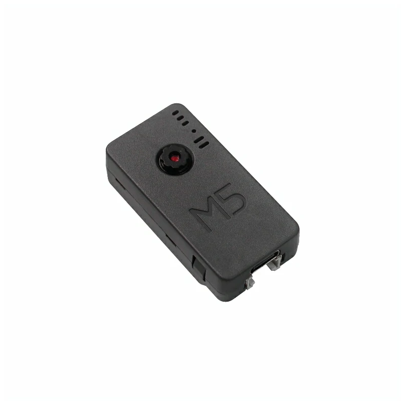
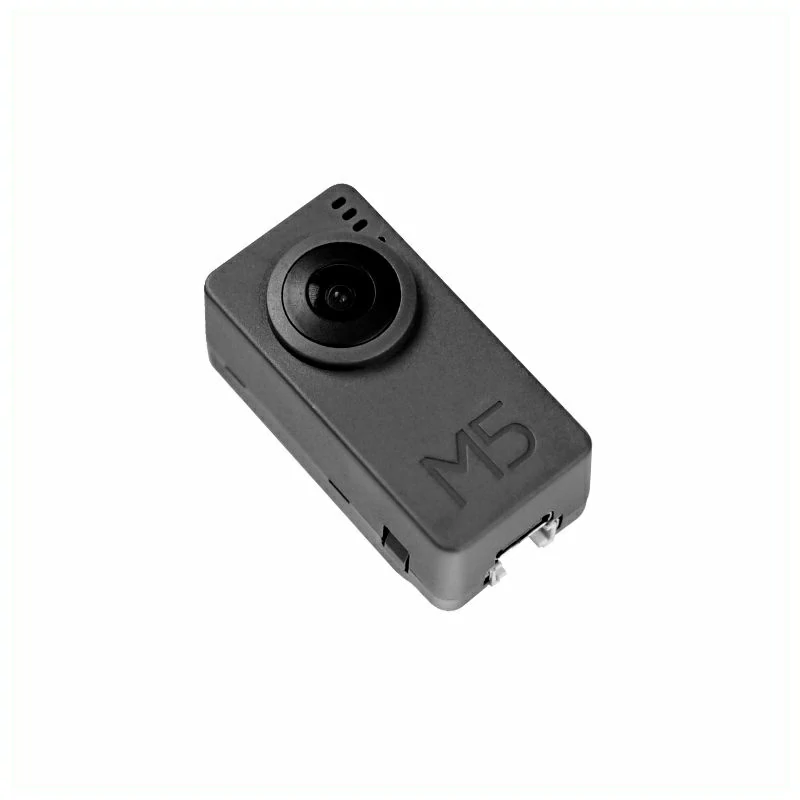
This tutorial explains in detail how to integrate TimerCamera Series devices with Home Assistant. It applies to TimerCamera (U082), TimerCamera-X (U082-X), and TimerCamera-F (U082-F).
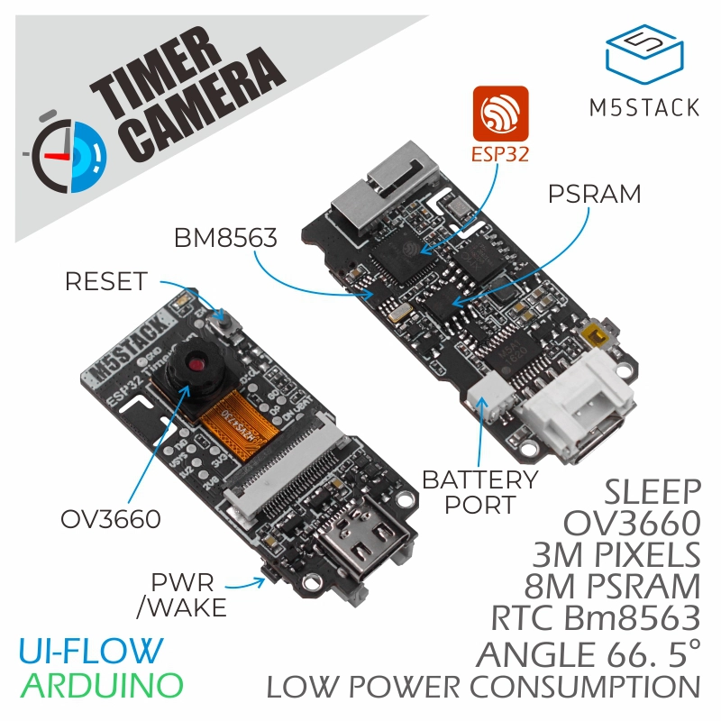
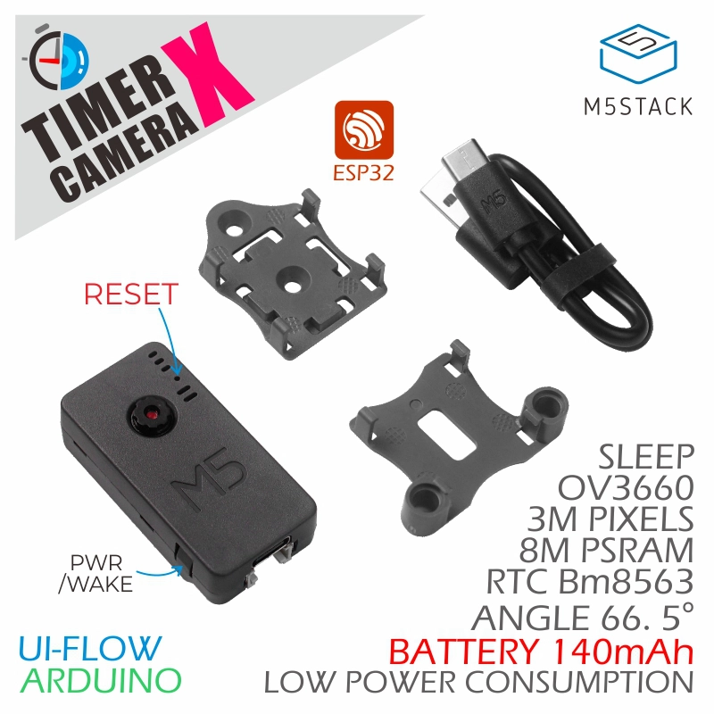
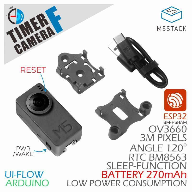
1. Preparation
Environment Setup
- Install Home Assistant by following the official Home Assistant documentation.
- Install the ESPHome Device Builder add-on by following the official ESPHome documentation. (Note: This tutorial is based on
ESPHome 2025.12.3. If you encounter compilation errors, switch to this version for verification.)
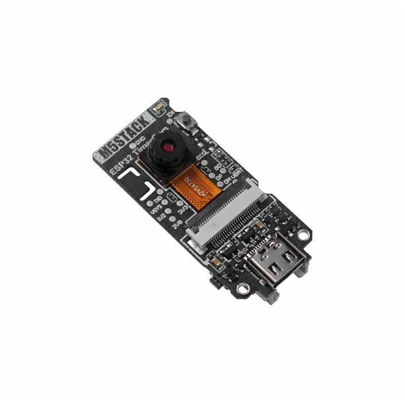
Hardware
References
2. Online Flashing
Click the Online Flashing button below and follow the prompts to flash the firmware and configure Wi-Fi. You can then quickly experience TimerCamera Series integration with Home Assistant.
For detailed flashing and configuration steps, refer to the Online ESPHome Firmware Flashing and Configuration Guide.
After completing online flashing, you do not need to perform the "Firmware Compilation & Flashing" steps. Proceed directly to 4. Getting Started.
3. Firmware Compilation & Flashing
This section explains how to recompile the project from the yaml configuration file for secondary development, feature modifications, or adding new features.
Create Device
Open ESPHome Builder, click
NEW DEVICEin the lower right corner to create a new device.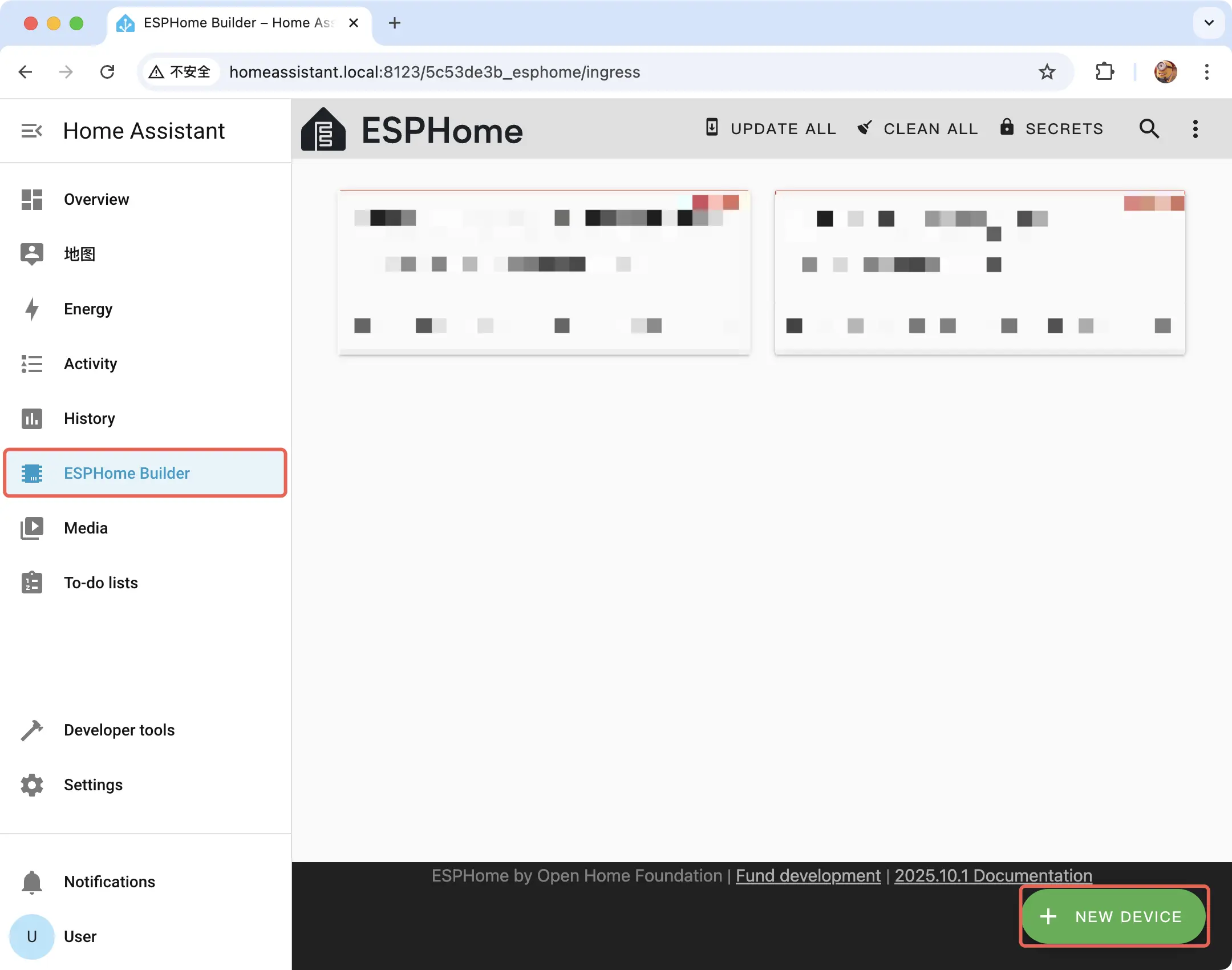
Click
CONTINUEin the pop-up window.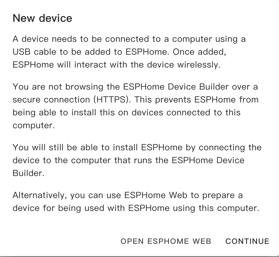
Select
New Device Setupto create a new configuration file.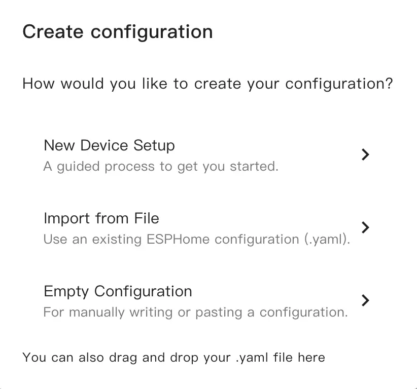
Name the new configuration file.
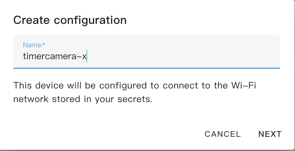
Select the device type, keep the default configuration here, and select
ESP32.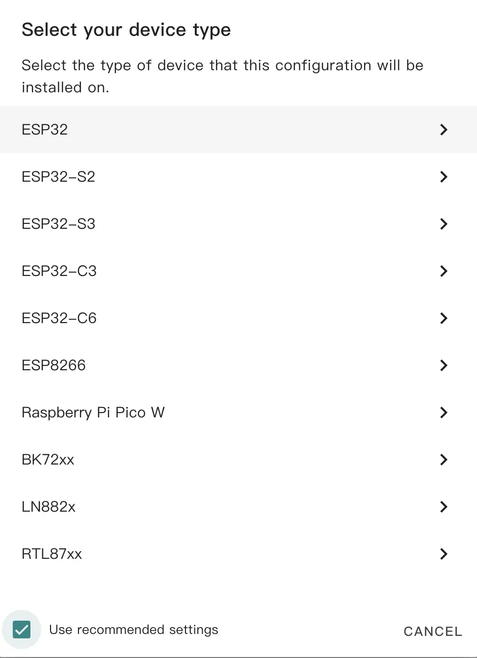
Copy the Encryption Key for backup, and click
SKIPto skip.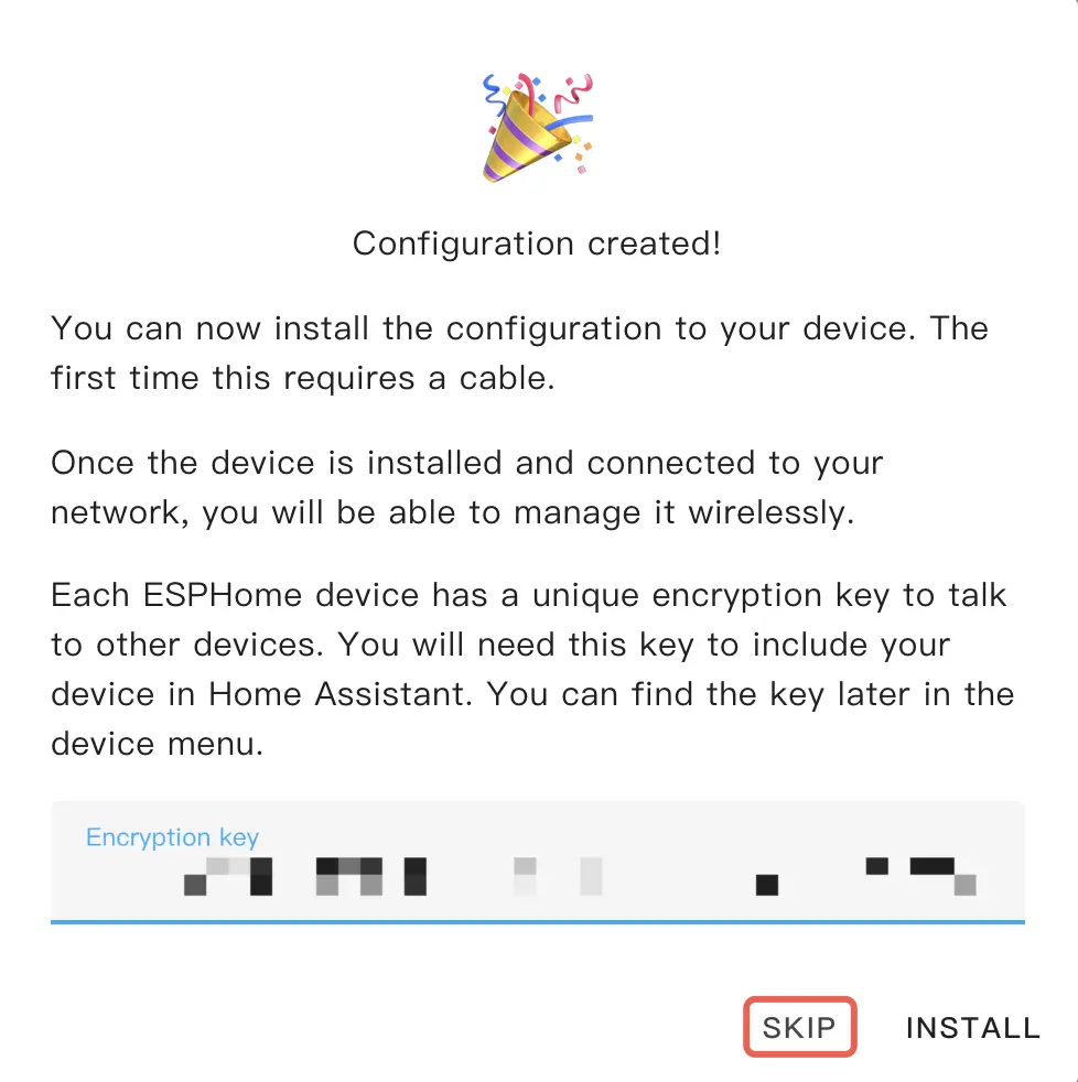
Modify Configuration
Click
EDITunder the generated configuration file card to edit.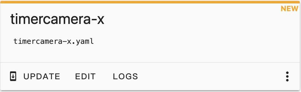
Open the configuration file for modification
- Add the PSRAM component.
psram:
  mode: quad
speed: 80MHz- Add I2C and ESP32 Camera components.
i2c:
  - id: bsp_i2c
    sda: GPIO12
    scl: GPIO14
  - id: cam_i2c
    sda: GPIO25
    scl: GPIO23

esp32_camera:
  name: OV3660 Camera
  external_clock:
    pin: GPIO27
    frequency: 20MHz
  i2c_id: cam_i2c
  data_pins: [GPIO32, GPIO35, GPIO34, GPIO5, GPIO39, GPIO18, GPIO36, GPIO19]
  vsync_pin: GPIO22
  href_pin: GPIO26
  pixel_clock_pin: GPIO21
  reset_pin: GPIO15
  resolution: 640x480
jpeg_quality: 10The default image configuration is used here. To change the configuration, you can refer to the configuration examples provided by ESPHome.
- Add the RTC Time component.
esphome:
  name: timercamera-x
  friendly_name: timercamera-x
  ...
  on_boot:
    then:
      # read the RTC time once when the system boots
      bm8563.read_time:

...
time:
  - platform: bm8563
    i2c_id: bsp_i2c
    # repeated synchronization is not necessary unless the external RTC
    # is much more accurate than the internal clock
    update_interval: never
  - platform: homeassistant
    # instead try to synchronize via network repeatedly ...
    on_time_sync:
      then:
        # ... and update the RTC when the synchronization was successful
bm8563.write_time:The system will read the time information in the RTC when it starts. After connecting to Home Assistant, it will automatically synchronize the Home Assistant time information.
- Configure LED.
output:
  - platform: ledc
    id: blue_led
    pin: GPIO2

light:
  - platform: monochromatic
    output: blue_led
    name: "Blue LED"
restore_mode: RESTORE_DEFAULT_ONThe blue LED will be turned on by default after the device is powered on. You can control the LED switch and brightness in Home Assistant.
- Use battery.
switch:
  - platform: gpio
    id: bat_hold_pin
    name: "Battery Hold Pin"
    pin: GPIO33
restore_mode: RESTORE_DEFAULT_ONGPIO33 is used here to control whether to use the battery. Turning it on and keeping it pulled high allows the battery to work. By default, it will stay high. If this switch is turned off, the device will shut down when there is no external power supply.
- Monitor battery level information.
TimerCamera-X and TimerCamera-F come pre-installed with a battery. You can obtain battery voltage information through the ADC reading of GPIO38, and get approximate battery level information after conversion:
sensor:
  - platform: adc
    pin: GPIO38
    attenuation: 12dB
    name: "Battery Voltage"
    id: battery_voltage
    update_interval: 10s
    filters:
      - multiply: 1.51

  - platform: template
    id: battery_percent
    name: "Battery Percentage"
    unit_of_measurement: "%"
    accuracy_decimals: 0
    lambda: |-
      float voltage = id(battery_voltage).state;
      float min_voltage = 3.350f;
      float max_voltage = 4.150f;

      if (voltage <= min_voltage) return 0.0;
      if (voltage >= max_voltage) return 100.0;

      float percent = ((voltage - min_voltage) / (max_voltage - min_voltage)) * 100.0;
return percent;BAT_HOLD_Pin (GPIO33) is kept high. If the HOLD state is not maintained, battery power will not be used and the ADC reading will be very low (<1V). If external USB power is connected while the HOLD state is maintained, the voltage shown here is the charging voltage.Compile Firmware
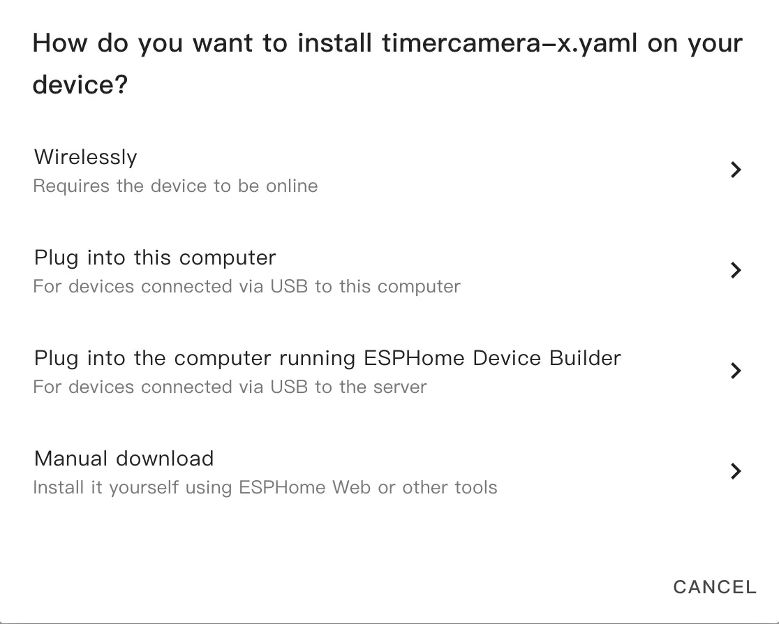
- After the modification is complete, click
SAVEandINSTALLin the upper right corner, and selectManual Downloadin the pop-up options.
After the compilation is complete, click the
Downloadbutton and selectFactory Formatto download the firmware.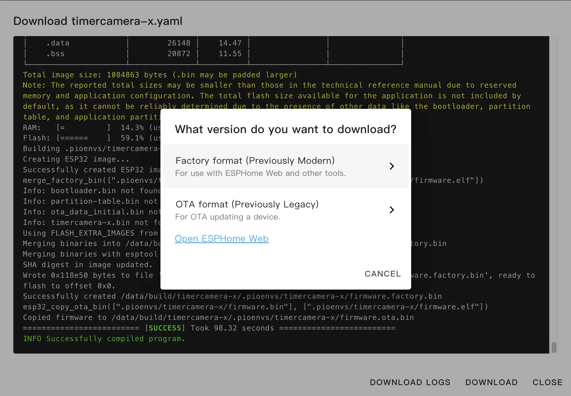
Flash Firmware
Connect the kit to the host via a USB Type-C data cable, open ESPHome Web, and click
CONNECTto connect the device.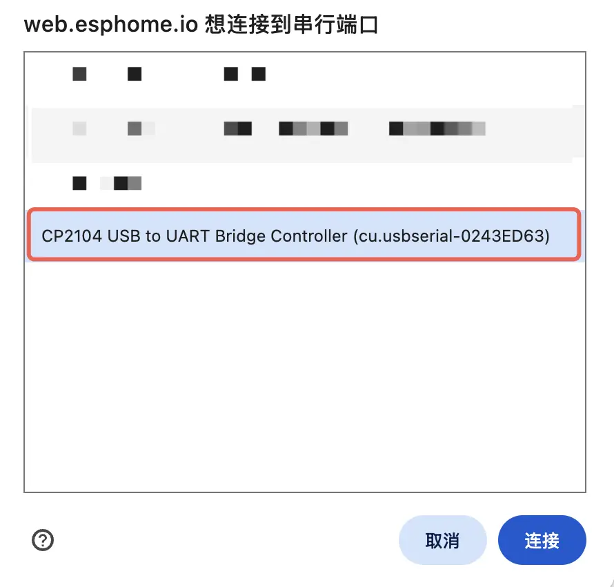
Click
INSTALLand select the previously compiled firmware for uploading.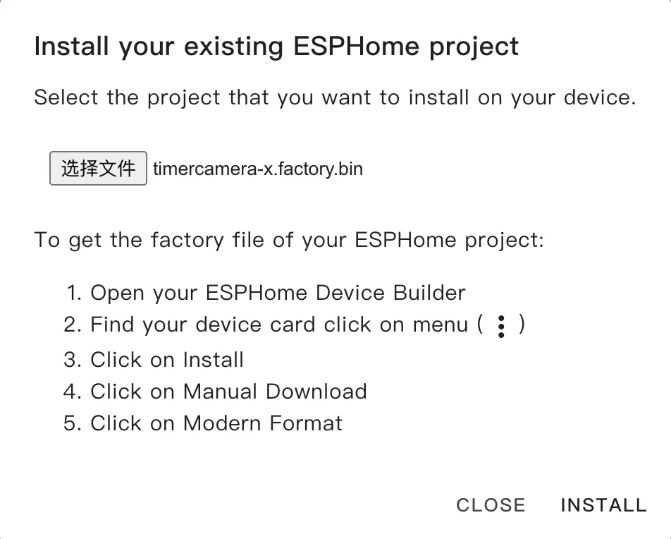
Click
INSTALLagain to flash, and wait for the process to complete.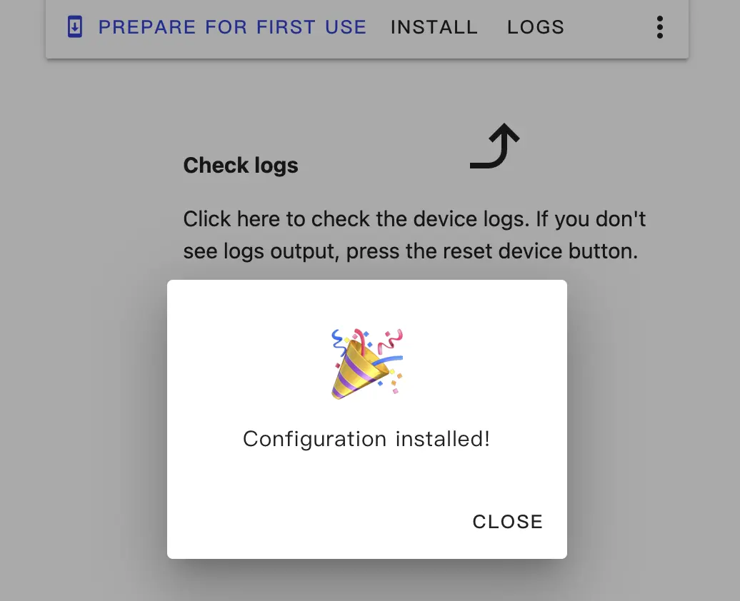
4. Getting Started
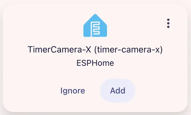
- After completing the firmware burning, the device will automatically perform Wi-Fi connection when powered on. Navigate to
Settings>Devices & Servicesto view the device status. ClickAddto add the device to Home Assistant.
- Dashboard example:
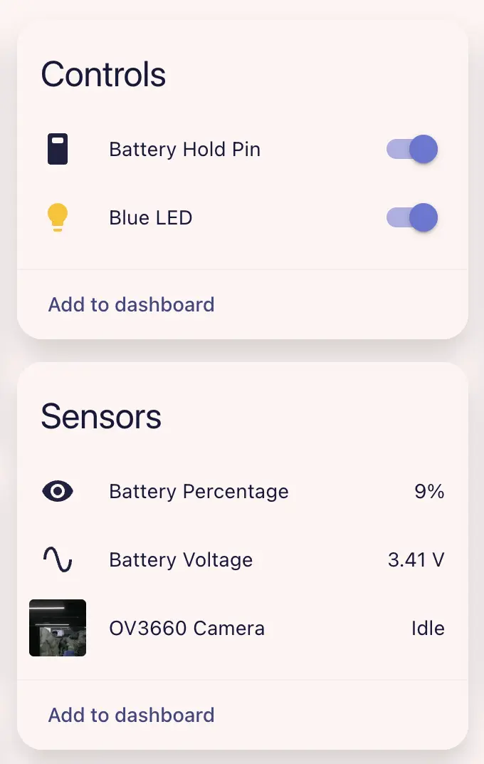
- Click on the camera entity to view the real-time preview screen.
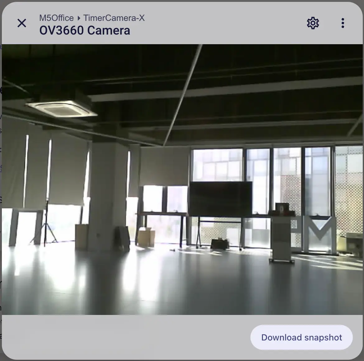
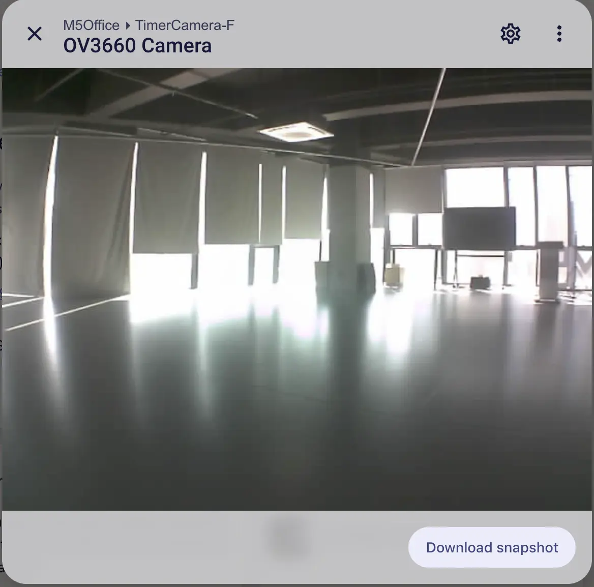
TimerCamera (TimerCamera-X) is shown on the left. TimerCamera-F uses a fisheye lens and is shown on the right.