StackFlow AI プラットフォーム
デバイスとクイックスタート
モデルの紹介
Qwen3
DeepSeek-R1
AI Pyramid Applications
アプリケーション
CVビジョンアプリケーション
VLMマルチモーダル
大規模言語モデル (LLM)
音声アシスタント
AI Pyramid EC Proxy ハードウェア制御
1. 説明
AI Pyramid のデフォルトイメージには、メインシステムとエンベデッドコントローラ(EC)間の通信および管理を実現するための「EC Proxy」エンベデッドコントローラ通信システムが内蔵されています。EC Proxy は、下位層のハードウェアに対して統一された抽象化レイヤーを提供し、具体的なハードウェアの実装詳細をカプセル化して、上位層のシステムに標準化された制御インターフェースを公開します。AI Pyramid 上のRGB LED、冷却ファン、電源管理、ボタンなどの周辺機器機能は、EC Proxy を通じて制御できます。AI Pyramid の起動後、EC Proxy サービスは自動的に有効になります。ユーザーはec_cliコマンドラインツールを使用してハードウェアリソースを操作でき、下位層のハードウェアと直接やり取りする必要はありません。
┌─────────────────┐     Modbus RTU      ┌──────────────────┐      ZMQ RPC/PUB     ┌─────────────┐
│   Hardware EC   │ ◄─────────────────► │   EC Proxy       │ ◄──────────────────► │   Client    │
│   (STM32/MCU)   │   /dev/ttyS3        │   Server         │   IPC/TCP Sockets    │   (CLI/App) │
└─────────────────┘ 115200-921600bps └──────────────────┘ └─────────────┘2. ハードウェア制御
ec_cli deviceと入力すると、ハードウェア制御に関するコマンドを確認できます。
root@m5stack-AI-Pyramid:~# ec_cli device
usage: ec_cli [options] ...
options:
-r, --rgb Get or set RGB LED display mode
--poweron_time Get or set the scheduled power-on time
--poweroff_time Get or set the scheduled power-off time
--rgb_size Get or set the number of RGB LEDs in the array
--rgb_get_color Get the color value of a specific RGB LED
--rgb_set_color Set color for a specific RGB LED, example: cli --rgb_set_color -d '{"rgb_index":0,"rgb_color":255}'
-f, --fan Get or set the fan PWM duty cycle
-F, --fanspeed Get the current fan rotation speed in RPM
--pd_power_info Get the USB PD power delivery information
-B, --board Get the board power consumption information
--ip_eth0 Get or set the IP address for Ethernet interface eth0
--ip_eth1 Get or set the IP address for Ethernet interface eth1
--ip_wlan Get or set the IP address for wireless LAN interface
-l, --lcd Get or set the LCD display mode
--lcd_ram Set the LCD RAM buffer data directly
-c, --vddcpu Get or set the CPU core voltage (VDD)
--modbus_speed Get or set the Modbus communication baud rate
-p, --ext_power Control the external power supply output
-b, --board_power Control the main board power switch
--pcie0 Set the PCIe slot 0 switch on/off state
--pcie1 Set the PCIe slot 1 switch on/off state
--gl3510_reset Reset the GL3510 USB hub controller
--usbds1_big Set the high-power mode for USB downstream port 1
--usbds2_big Set the high-power mode for USB downstream port 2
--usbds1 Set the switch on/off state for USB downstream port 1
--usbds2 Set the switch on/off state for USB downstream port 2
--usbds3 Set the switch on/off state for USB downstream port 3
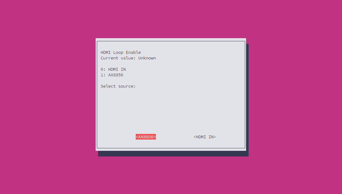
--hdmi_loop_en Switch HDMI OUT port input source between IN and AX8850
--grove_uart Set the switch on/off state for Grove UART interface
--grove_iic Set the switch on/off state for Grove I2C interface
--flash_switch Save switch configuration to flash memory (stores coil registers 4-14)
--flash_value Save value configuration to flash memory (stores holding registers 1, 2, 11, 12, 14, 16-21)
--poweroff Trigger the system power-off sequence
--lcd_brightness Get or set the LCD backlight brightness level
-P, --lcd_putc Output a character or string to the LCD display
--i2c_set_reg Write a value to an I2C device register
--i2c_get_reg Read a value from an I2C device register
--ec_button_head_event Get or set the event handler for EC head button press
--soc_button_head_event Get or set the event handler for SoC head button press
--ec_button_lcd_event Get or set the event handler for EC LCD button press
--fun_auto Get or set the automatic control mode for the proxy service
--ec_modbus_set_bit Set a specific bit in the EC Modbus coil register
--ec_modbus_get_bit Get a specific bit value from the EC Modbus coil register
--ec_modbus_input_bits Read the EC Modbus discrete input bits status
--ec_modbus_input_registers Read the EC Modbus input registers values
--ec_modbus_set_hold_registers Write values to the EC Modbus holding registers
--ec_modbus_get_hold_registers Read values from the EC Modbus holding registers
--pcie0_exists Check if a PCIe device is present in slot 0
--pcie1_exists Check if a PCIe device is present in slot 1
--V3_3_good Check if the 3.3V power rail is within normal operating range
--V1_8_good Check if the 1.8V power rail is within normal operating range
--head_button Get the current state of the head button (pressed/released)
--lcd_button Get the current state of the LCD button (pressed/released)
--version Get the EC firmware version information
-d, --data call param (string [=])
-D, --DataRaw call param raw (string [=])
-?, --help print this messageRGB LED 制御
RGB LED の動作モードを設定します。
ec_cli device --rgb -d 4| RGB LED Mode | 説明 |
|---|---|
| 0 | rgb_set_color 指令で制御 |
| 1 | カラーグラデーション |
| 2 | 呼吸エフェクト |
| 3 | 流れる水エフェクト |
| 4 | 分散エフェクト |
| 5 | 集合エフェクト |
rgb_set_colorコマンドを使用して個別の RGB LED の色を設定します。このコマンドはモード 0 でのみ有効です。注意:現在のインターフェースは範囲指定による色の設定には対応していません。入力するrgb_colorは 10 進数のRGB888エンコードです。(例:0x00FF00 == 65280)
ec_cli device --rgb_set_color -d '{"rgb_index":0,"rgb_color": 65280}'ファン制御
ファンの PWM デューティ比を 80% に設定します。
ec_cli device --fan -d 80{
"created": 1769747093,
"data": "ok",
"object": "",
"request_id": "",
"work_id": "fun_set_pwm"
}ファンの回転数(RPM)を読み取ります。
ec_cli device --fanspeed{
"created": 1769753372,
"data": 9060,
"object": "",
"request_id": "",
"work_id": "get_input_registers"
}ネットワーク情報
ec_cli device --ip_eth0
ec_cli device --ip_eth1
ec_cli device --ip_wlanPD 電源情報
ec_cli device --pd_power_info{
"created": 1769753175,
"data": { "voltage": "20 V", "current": "1.25 A" },
"object": "",
"request_id": "",
"work_id": "pd_info"
}電源管理
現在のデバイスの消費電力情報を確認します。
ec_cli device --board{
"created": 1769756427,
"data": {
"pcie0_mv": 3352,
"pcie0_ma": 0,
"pcie1_mv": 3328,
"pcie1_ma": 0,
"usb1_mv": 5040,
"usb1_ma": 0,
"usb2_mv": 5040,
"usb2_ma": 0,
"INVDD_mv": 20112,
"INVDD_ma": 292,
"EXTVDD_mv": 20112,
"EXTVDD_ma": 28
},
"object": "",
"request_id": "",
"work_id": "board_get_power_info"
}USB インターフェース給電
USB インターフェースの出力給電をオンにします。デバイス内部の USB 3.0 #4 インターフェースは常時オンの状態です。
ec_cli device --usbds1 -d 1
ec_cli device --usbds2 -d 1
ec_cli device --usbds3 -d 1USB インターフェースの出力給電をオフにします。
ec_cli device --usbds1 -d 0
ec_cli device --usbds2 -d 0
ec_cli device --usbds3 -d 0USB インターフェースの給電強化を設定します。インターフェースのデフォルト出力能力は最大 400mA ですが、強化を有効にすると最大 800mA になります。現在、USB #1 / #2 インターフェースのみが給電強化に対応しています。
ec_cli device --usbds1_big -d 1
ec_cli device --usbds2_big -d 1OLED
OLED の表示モードを設定します。
ec_cli device --lcd -d 4| RGB LED Mode | 説明 |
|---|---|
| 0 | M5Stack 文字 |
| 1 | インターフェース電圧表示、3 秒ごとに更新 |
| 2 | IP 表示、3 秒ごとに更新 |
| 3 | ARM マッピング |
| 4 | 文字表示モード、lcd_putc 指令で制御 |
lcd_putcコマンドを使用して OLED 画面に文字を出力します。このコマンドはモード 4 でのみ有効です。
ec_cli device --lcd_putc -d "Hello World!"空白文字を書き込むことで画面をクリアできます。
ec_cli device --lcd_putc -d " "3. ステータス監視
ec_cli echoと入力すると、ハードウェア制御に関するコマンドを確認できます。現在のバージョンでは、本体上部ボタンの状態の読み取りのみをサポートしています。
root@m5stack-AI-Pyramid:~# ec_cli echo
usage: ec_cli [options] ...
options:
  -b, --button    button event
-?, --help print this messageec_cli echo --button本体上部ボタンを押した際:
{ "created":1769747540,"data":{"code":0,"vale":204},"object":"","request_id":"","work_id":"buttons_thread" }
{ "created":1769747540,"data":{"code":1,"vale":204},"object":"","request_id":"","work_id":"buttons_thread" }
{ "created":1769747540,"data":{"code":0,"vale":204},"object":"","request_id":"","work_id":"buttons_thread" }
{ "created":1769747540,"data":{"code":1,"vale":204},"object":"","request_id":"","work_id":"buttons_thread" }4. Core-Config
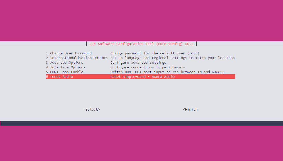
コマンドライン以外に、Core-Config を使用して GUI 画面を開き設定することも可能です。
core-config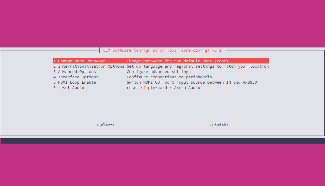
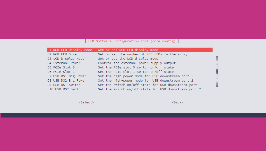
Interface Optionには、USB インターフェースの給電やファンの回転数など、よく使われるハードウェア制御オプションが含まれています。設定内容はec_cliコマンドラインツールと同一です。
ディスプレイ出力設定
この設定は AI Pyramid-Pro に適用されます。Display 出力インターフェースの信号源を、Display Input インターフェースからにするか、または AX8850 の内部デフォルト出力を直接使用するかを設定できます。
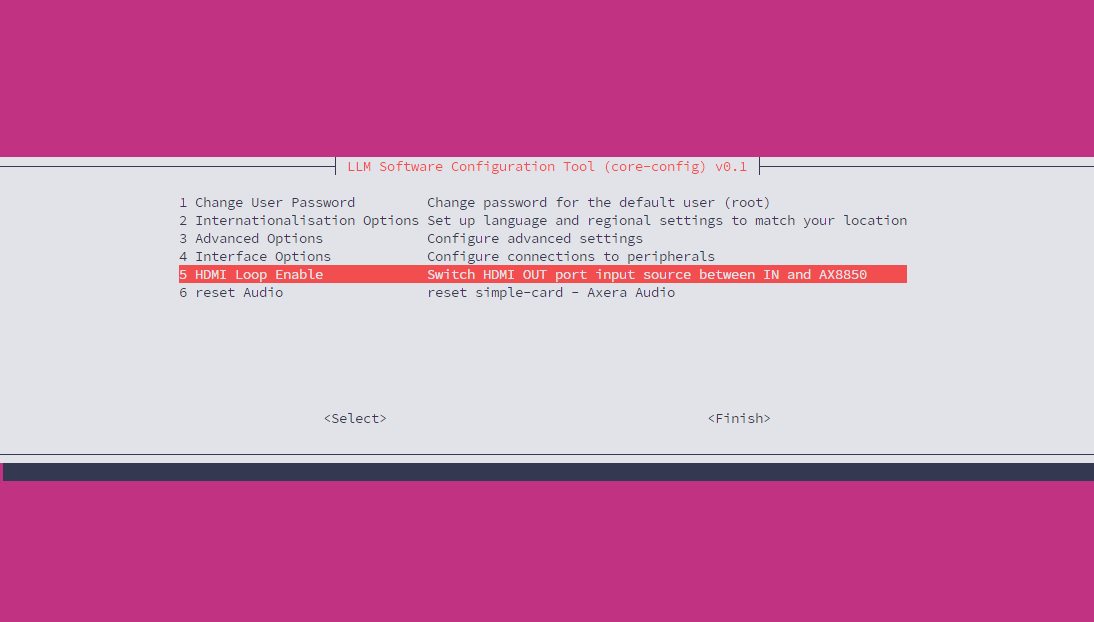
Reset Audio