Unit RollerCAN User Guide
1. Power Supply
Unit RollerCAN provides the following two power supply options:
- Via the CAN (XT30(2+2)PW-M) interface: Supports 6-16V@DC and integrates a DC-DC step-down circuit to power the controller.
- Via the Grove interface: 5V@DC.


2. Device Configuration
Configuration Mode
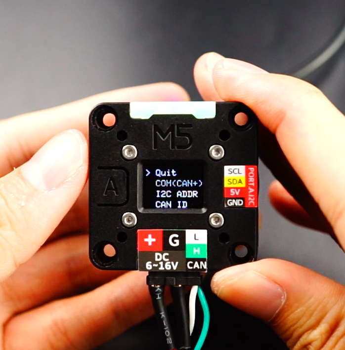
Unit RollerCAN integrates an OLED and physical buttons for user input and interaction. Before deploying the motor, you can perform some initial configuration based on your needs. Refer to the steps below to enter configuration mode:
- Long press the bottom button (Button A)
- Power on the device
- Enter configuration mode
- Once in the configuration menu, rotate the motor to switch options, and press the button to select/return.
Communication Modes
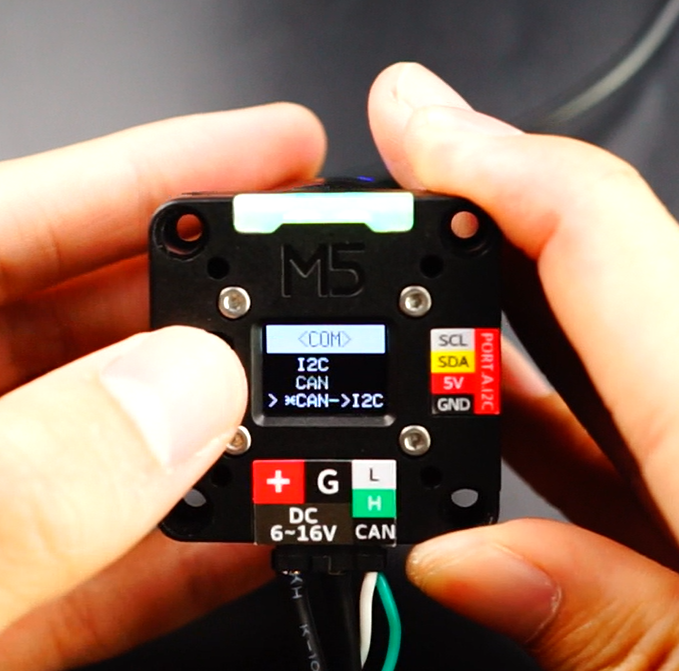
Unit RollerCAN currently offers the following communication options. Users can choose the appropriate interface and protocol based on the deployment scenario:
- I2C Mode: In this mode, the motor is controlled via the I2C communication interface.
- CAN Mode: In this mode, the motor is controlled via the CAN communication interface.
- CAN->I2C Mode: In this mode, the motor is controlled via the CAN communication interface, while supporting CAN->I2C forwarding commands, enabling the reading/writing of I2C device data via a bridge.
Communication Addresses
- I2C ADDR: Set the I2C address when the device is in I2C communication mode as a slave.
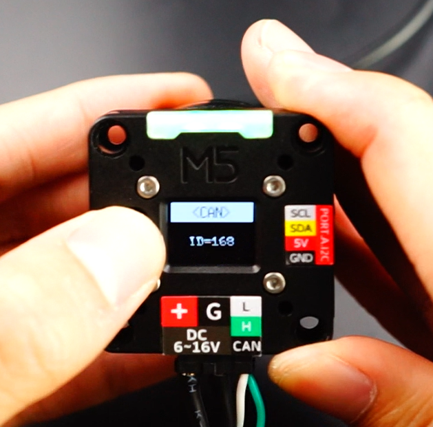
- CAN ID: Set the ID used for communication in CAN mode. The range is 0-255, with the default value being 168 (0xA8).
PID Presets
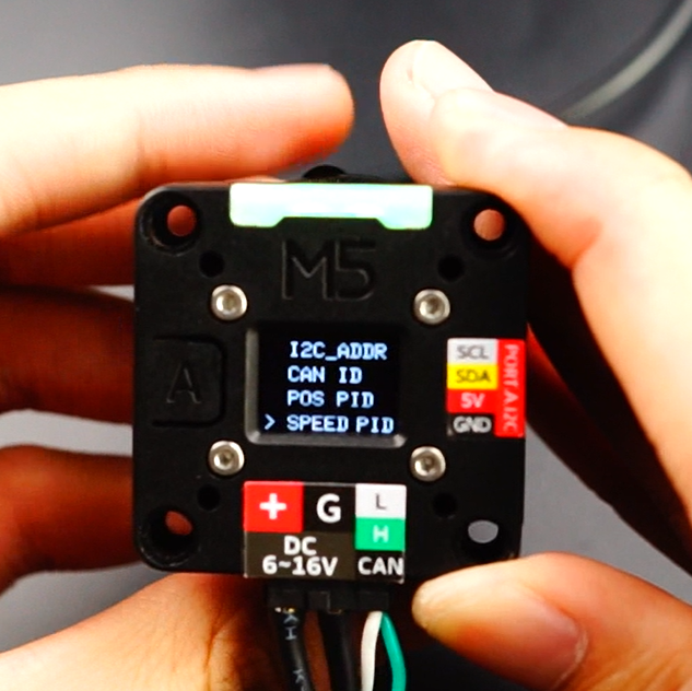
Configure the PID for speed and position control modes. You can choose from the following presets, optimized for different scenarios. Users are recommended to fine-tune the parameters based on their actual needs.
- Default user settings
- Light load optimized settings
- Medium load optimized settings
- Heavy load optimized settings
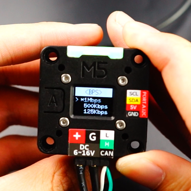
CAN Baud Rate Configuration
When in CAN communication mode, you can set the device communication rate (bps). Currently supported options are: 1M, 500K, 125K.
RGB Brightness
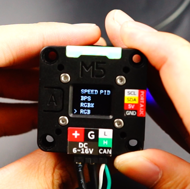
Adjust the brightness of the RGB LED: 0-100%.
RGB Working Modes
- System Auto Mode: Automatically switches colors based on the motor's current operating mode:
- Green: Speed Mode
- Blue: Position Mode
- Yellow: Current Mode
- Purple: Encoder Mode
- Red: Error Alarm
- User Mode: Users can customize the indicator light colors.
JAM Protection
Set the motor stall protection. When a stall is detected, the motor will automatically lock to prevent damage.
Range Protection
Set the motor rotation range protection. When enabled, if the encoder value falls below -2,100,000,000 or exceeds 2,100,000,000, the motor will stop rotating and enter protection mode.
3. Motor Operating Modes
Unit RollerCAN provides four operating modes, which can be configured through communication commands (refer to the case programs and communication protocol at the bottom of the page):
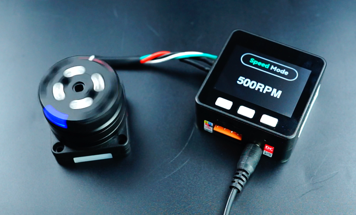
- Speed Mode (Green): Controls the motor to run at a specified target speed (RPM).
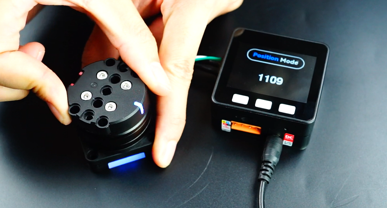
- Position Mode (Blue): Controls the motor to rotate to a specified position (encoder value).
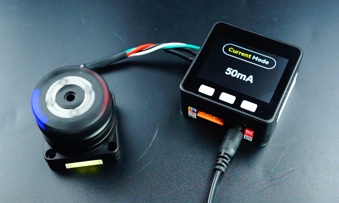
- Current Mode (Yellow): Controls the motor to run at a specified target current (mA).
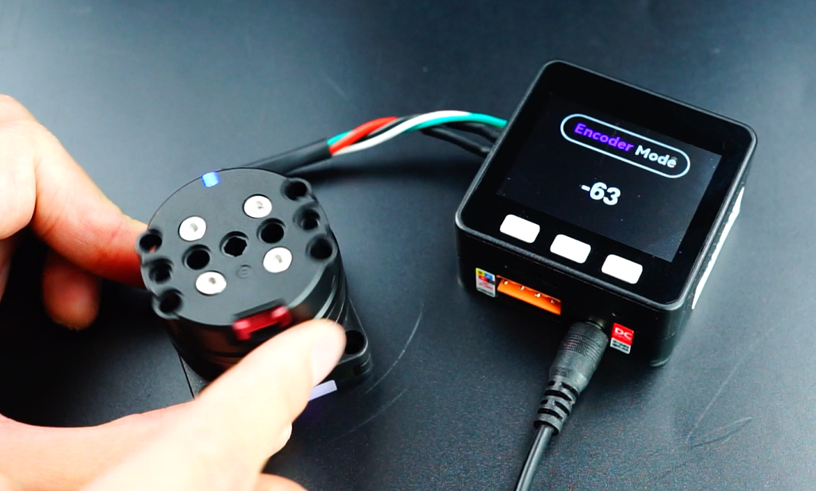
- Encoder Mode (Purple): The motor acts as an input device, collecting current encoder rotation values.
4. Device Wiring
CAN Control
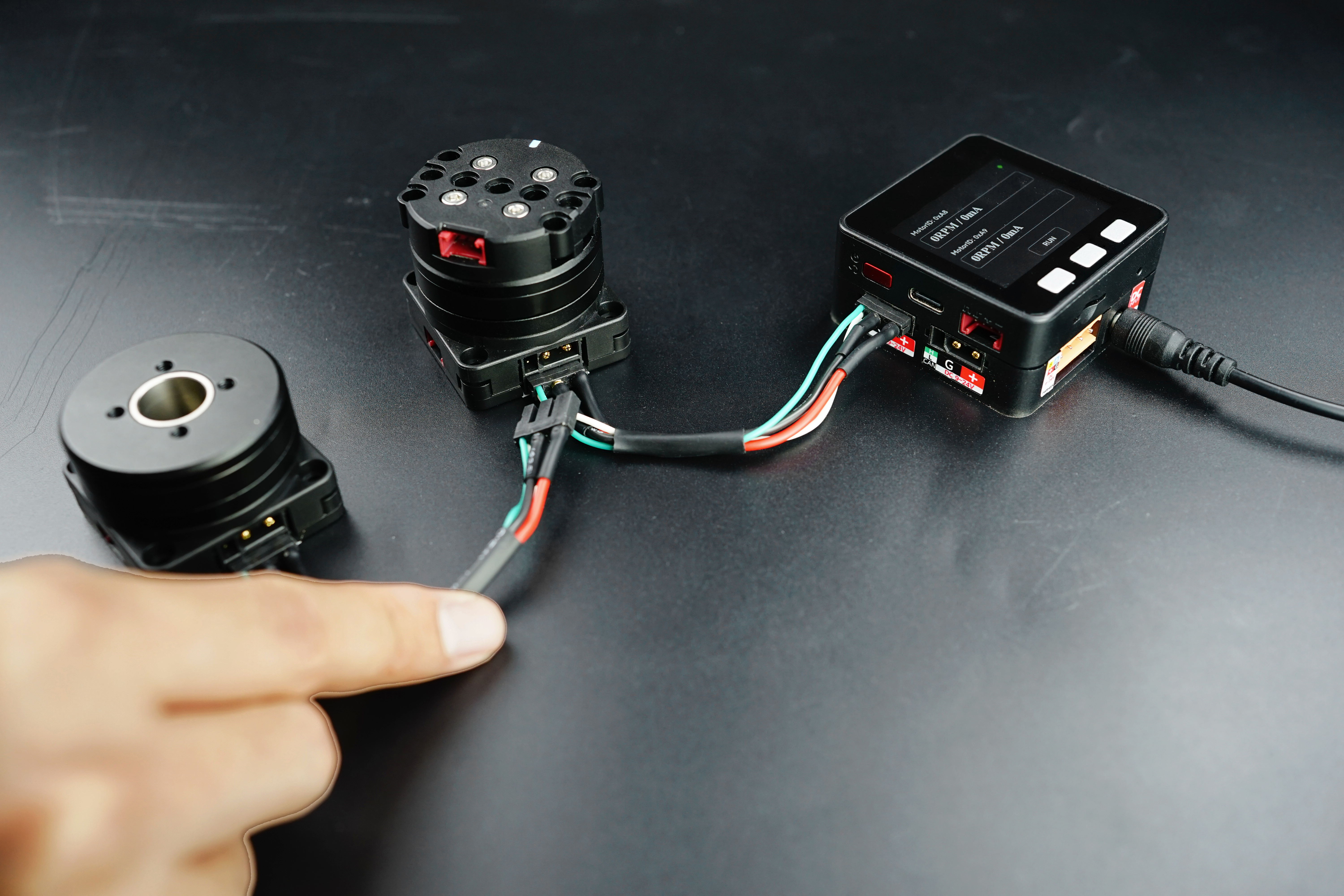
Multiple motors can be connected in a network via the XT30 interface using the PwrCAN Cable. Commands are sent to control the motors. Before use, configure each device with a different ID to distinguish between them during communication.
I2C Control
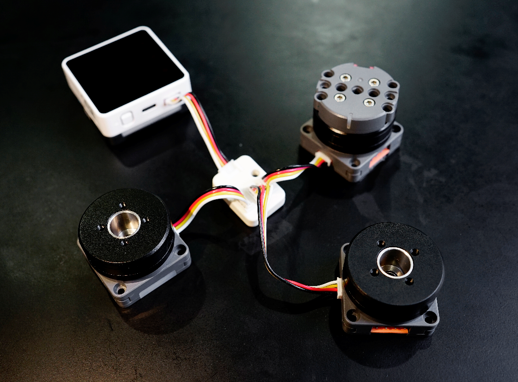
Multiple motors can be controlled via I2C by connecting them through the Unit Hub, enabling access to slave registers for control.
5. Structural Components
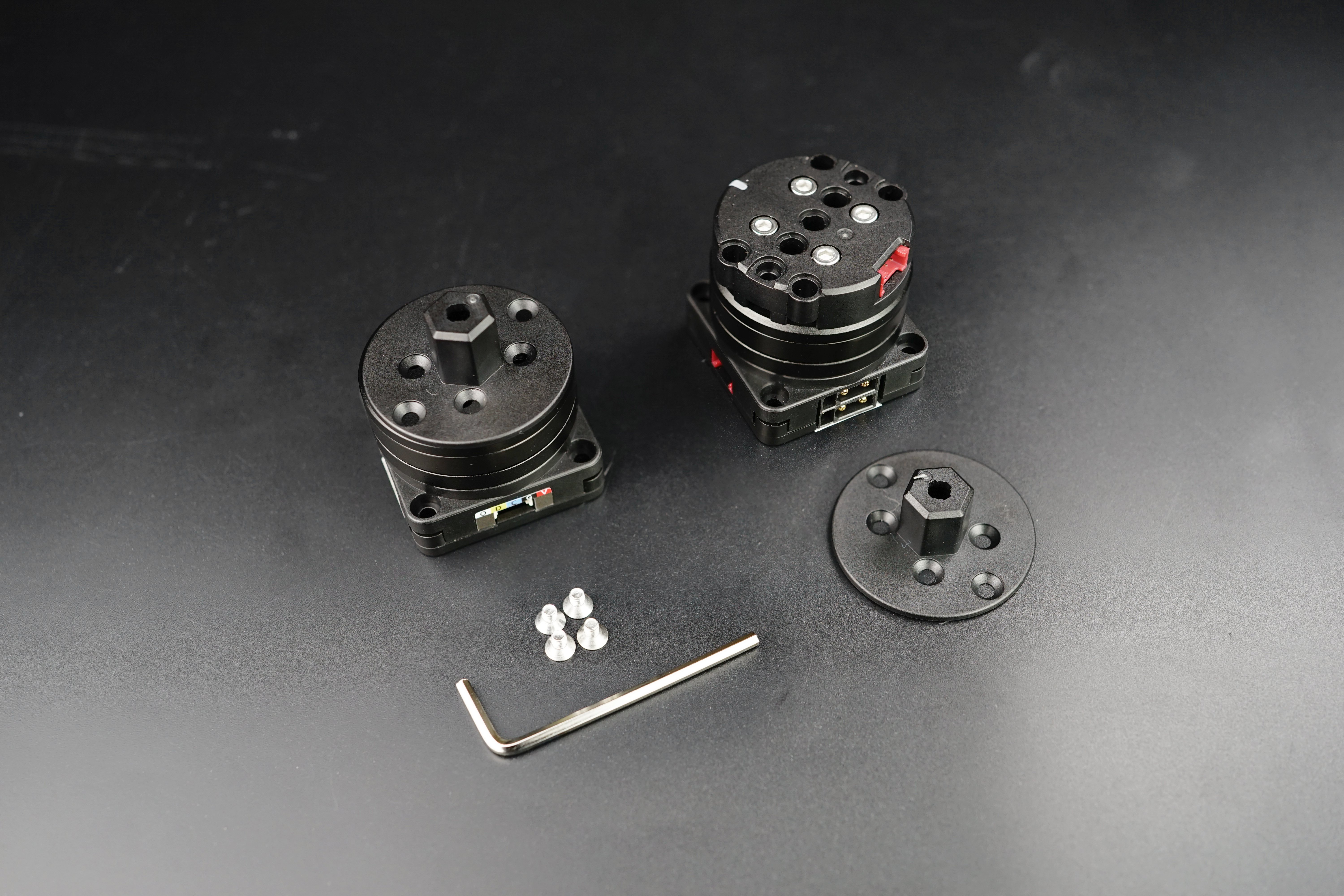
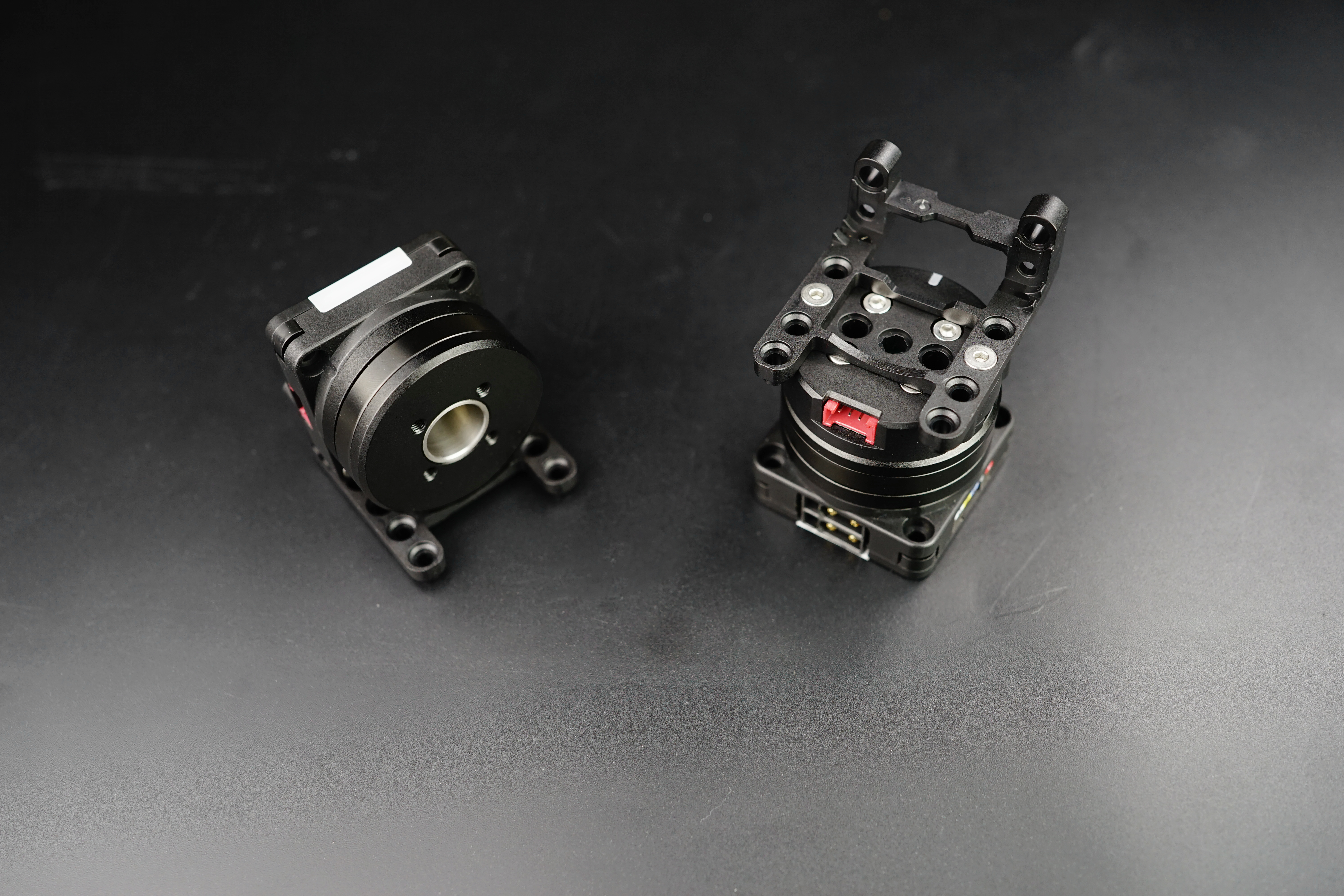
The Unit RollerCAN set includes a flange and LEGO-compatible bracket parts to help users build their own control devices. You can refer to the images below for mounting and installation.
6. Related Resources
Example Programs:
Communication Protocols:
