


Product Guide
Linux PC
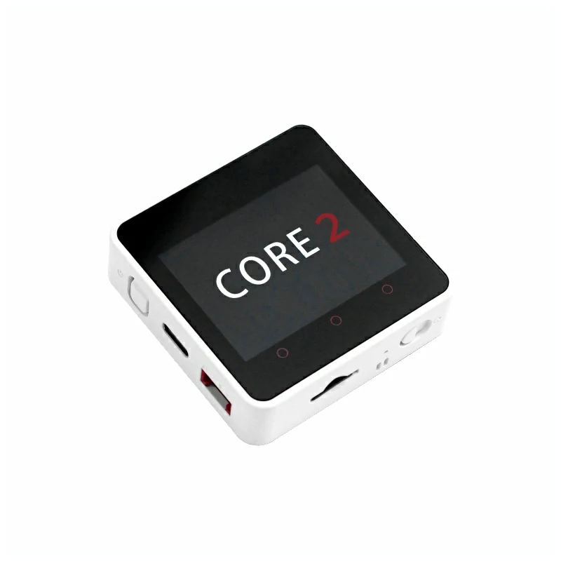
CardputerZero
AI Accelerator Card
LLM-8850 Card
Large Language Models
AI & Agent
Real-Time AI Voice Assistant
XiaoZhi Voice Assistant
AtomS3R-M12 Volcengine Kit
Offline Voice Recognition
Industrial Control
IoT Measuring Instruments
Air Quality
PowerHub
Module13.2 PPS
VAMeter
T-Lite
Input & Output Devices
Ethernet Camera
PoECAM
Wi-Fi Camera
Unit CamS3/-5MP
AI Camera
LoRa & LoRaWAN
Motor Control
Restore Factory Firmware
DIP Switch Usage Guide
Module ExtPort For Core2 DIP Switch Explanation Document
1. Overview
To avoid complications, the Module ExtPort For Core2 module uses DIP switches to flexibly switch the connection of key pins. Users can adjust the corresponding Grove pin configuration according to their needs.
2. DIP Switch Position and Pin Mapping
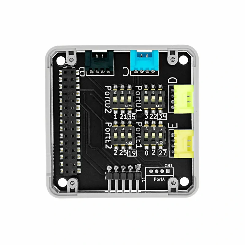
2.1 DIP Switch Position
The DIP switch is located in the specified position on the module, as shown in the image below:
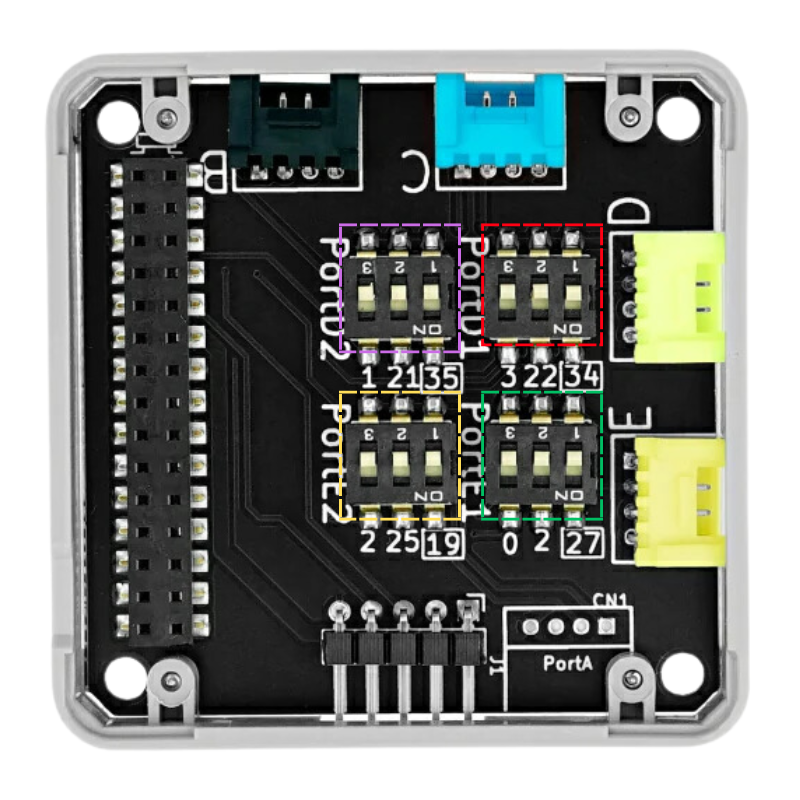
As shown in the image, the DIP switch is used to switch the signal pins of two Grove ports (Port D and Port E). The pin sequence for Port D and Port E is VDD GND PortD2 PortD1 and VDD GND PortE2 PortE1.
2.2 Pin Mapping Table
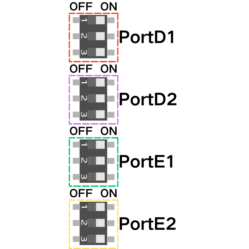
The available pin mappings for different hosts are as follows:
| CORE2 | |
|---|---|
| PortD1 | G34 |
| G22 | |
| G3 | |
| PortD2 | G35 |
| G21 | |
| G1 | |
| PortE1 | G27 |
| G2 | |
| G0 | |
| PortE2 | G19 |
| G25 | |
| G2 |
Note:
- PortD1, PortD2, PortE1, PortE2 can all be selected using the DIP switch to connect to specific pins. For example, on the Core2 host:
- PortD1: can be selected as G34, G22, or G3 (three options)
- PortD2: can be selected as G35, G21, or G1 (three options)
- PortE1: can be selected as G27, G2, or G0 (three options)
- PortE2: can be selected as G19, G25, or G2 (three options)
3. DIP Switch Adjustment Procedure
Please follow these steps to adjust the DIP switch configuration:
Power Off Operation
Before adjusting the DIP switch, ensure that the module is completely powered off to avoid hardware damage.Set the DIP Switch
Select the corresponding pin mapping based on the host you are using.
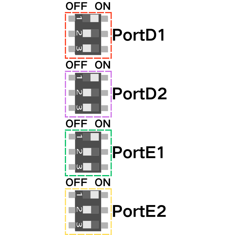
As shown in the image above, the DIP switch is set as follows: (Core2 + Module ExtPort For Core2)
PortD1 → G34
PortD2 → G35
PortE1 → G27
PortE2 → G19
- Rewire and Power On
After completing the DIP switch settings, reconnect the module and power it on for subsequent use.