Arduino 上手教程
2. 设备开发 & 案例程序
3. M5Unified
4. M5GFX
5. 拓展模块
Unit
Atomic
Base
IoT
Module 4In8Out Arduino 使用教程
1.准备工作
1.环境配置: 参考Arduino IDE上手教程完成IDE安装, 并根据实际使用的开发板安装对应的板管理, 与需要的驱动库。
2.使用到的驱动库:
3.使用到的硬件产品:

2.案例程序
案例说明
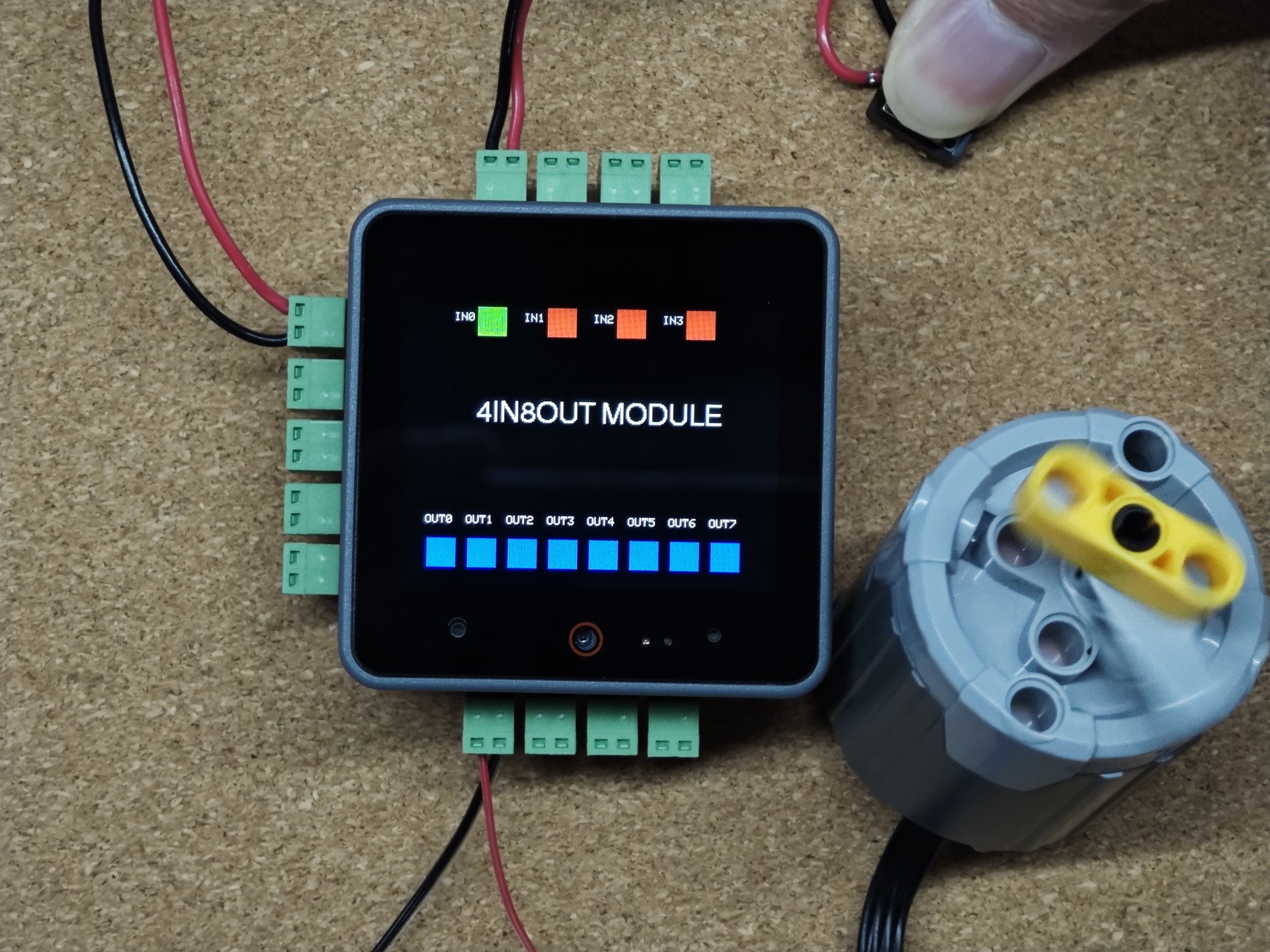
Module 4In8Out提供了4路无源信号输入接口与8路MOS驱动输出接口, 能够便捷的实现数字信号输入与负载控制。
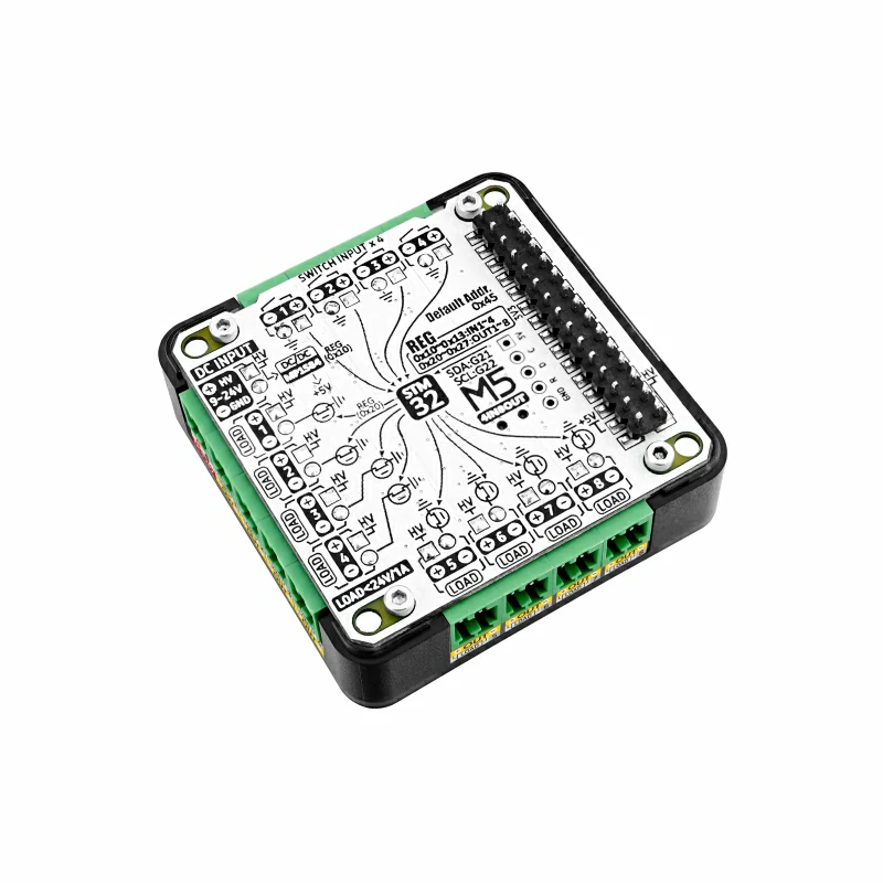
接线示意图
- 4x 输入接口:
- 要求输入电平<5V。
- 8x 输出接口:
- 输出接口的电源来自Power In接口<=24V, 因此驱动负载时必须提供在Power In接口提供匹配的电压。接口通过MOS管开关实现输出控制, 单路最大通断电流1A。

完整程序
基于M5Unified和M5GFX添加基本的显示, 和开关控制,实现电流值读取,和触摸控制电源通断。
cpp
1 2 3 4 5 6 7 8 9 10 11 12 13 14 15 16 17 18 19 20 21 22 23 24 25 26 27 28 29 30 31 32 33 34 35 36 37 38 39 40 41 42 43 44 45 46 47 48 49 50 51 52 53
#include <M5Unified.h>
#include "MODULE_4IN8OUT.h"

MODULE_4IN8OUT module;

void setup()
{
    M5.begin();

    i2c_port_t i2c_port = M5.In_I2C.getPort();
    i2c_port_t scl_pin  = M5.In_I2C.getSCL();
    i2c_port_t sda_pin  = M5.In_I2C.getSDA();
    auto twowire        = ((i2c_port == 1) ? &Wire1 : &Wire);

    while (!module.begin(twowire, sda_pin, scl_pin, MODULE_4IN8OUT_ADDR)) {
        Serial.println("4IN8OUT INIT ERROR");
        M5.Lcd.println("4IN8OUT INIT ERROR");
        delay(1000);
    };
    Serial.println("4IN8OUT INIT SUCCESS");
}

long interval = 0;
bool level    = false;

void loop()
{
    for (uint8_t i = 0; i < 4; i++) {
        if (module.getInput(i) != 1) {
            M5.Lcd.fillRect(60 + 60 * i, 0, 25, 25, TFT_GREEN);
        } else {
            M5.Lcd.fillRect(60 + 60 * i, 0, 25, 25, TFT_RED);
        }
        M5.Lcd.drawString("IN" + String(i), 40 + 60 * i, 5);
    }
    M5.Lcd.drawString("4IN8OUT MODULE", 60, 80, 4);
    if (millis() - interval > 1000) {
        interval = millis();
        level    = !level;
        for (uint8_t i = 0; i < 8; i++) {
            module.setOutput(i, level);
            if (level) {
                M5.Lcd.fillRect(20 + 35 * i, 200, 25, 25, TFT_BLACK);
                M5.Lcd.fillRect(20 + 35 * i, 200, 25, 25, TFT_BLUE);
            } else {
                M5.Lcd.fillRect(20 + 35 * i, 200, 25, 25, TFT_BLACK);
                M5.Lcd.drawRect(20 + 35 * i, 200, 25, 25, TFT_BLUE);
            }
            M5.Lcd.drawString("OUT" + String(i), 18 + 35 * i, 180);
        }
    }
    delay(500);
}3.编译上传
1.下载模式: 不同设备进行程序烧录前需要下载模式, 不同的主控设备该步骤可能有所不同。详情可参考Arduino IDE上手教程页面底部的设备程序下载教程列表, 查看具体的操作方式。
CoreS3长按复位按键(大约2秒)直到内部绿色LED灯亮起,便可松开,此时设备已进入下载模式,等待烧录。
.gif)
- 2.选中设备端口, 点击Arduino IDE左上角编译上传按钮, 等待程序完成编译并上传至设备。

4.输入监控&输出控制