Arduino 上手教程
2. 设备开发 & 案例程序
3. M5Unified
4. M5GFX
5. 拓展模块
Unit
Base
Cap
IoT
Module LoRa868 v1.2 Arduino 使用教程
1.准备工作
1.环境配置: 参考Arduino IDE上手教程完成IDE安装, 并根据实际使用的开发板安装对应的板管理, 与需要的驱动库。
2.使用到的驱动库:
3.使用到的硬件产品:

2.案例程序
案例说明
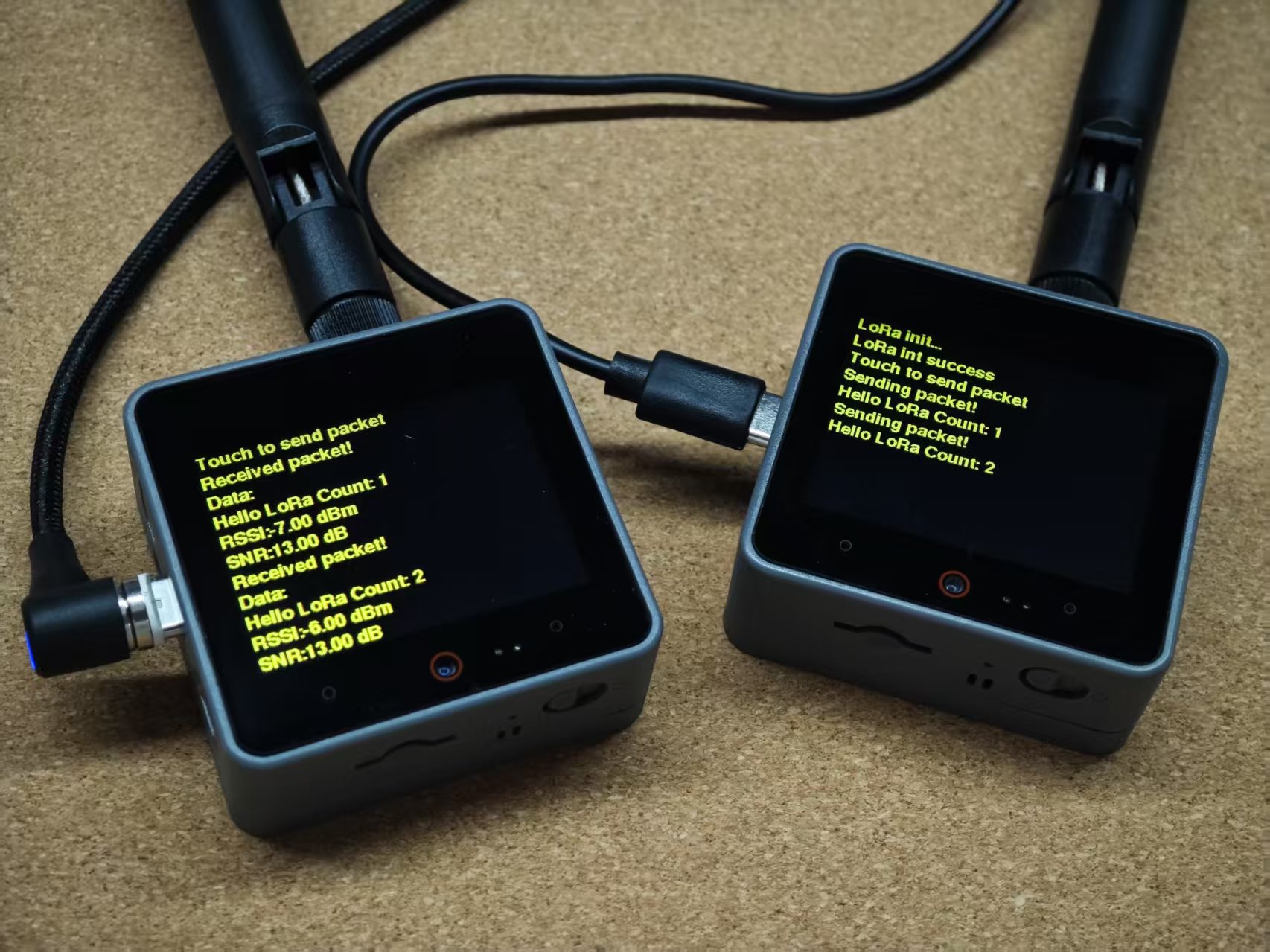
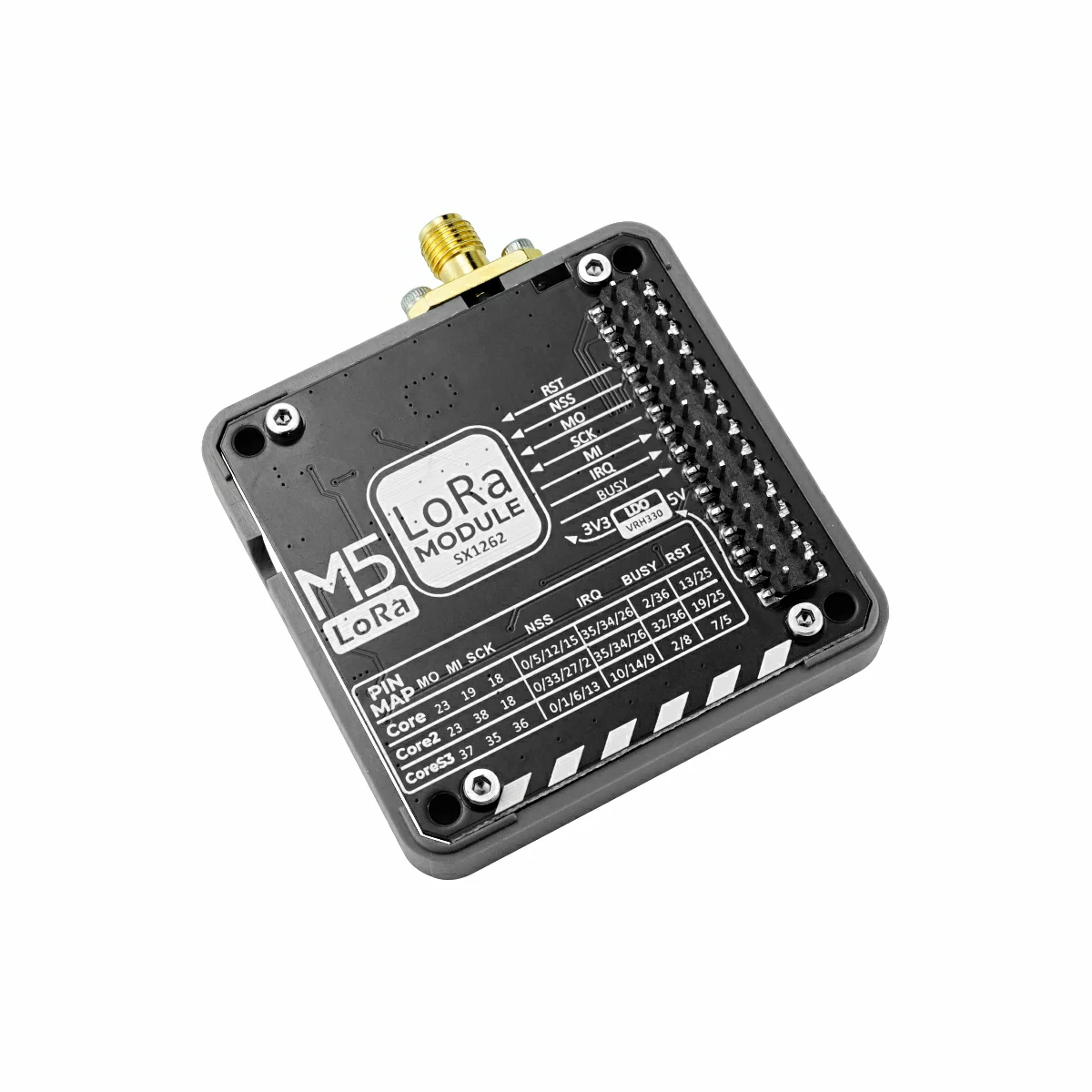
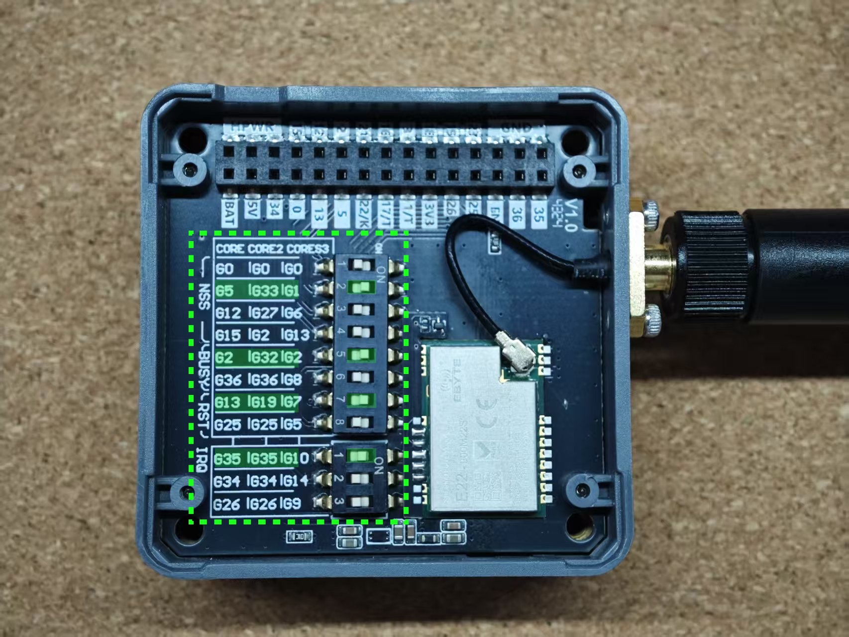
本案例采用 2 个 Module LoRa868 v1.2 模块与 2 个 CoreS3 主控,分别烧录相同的 LoRa 收发测试程序,用于实现点对点的数据通信。在与其他主控板配合使用时,请根据具体硬件连接情况,在程序中配置相应的 IO 引脚信息。此外,Module LoRa868 v1.2 支持通过底部的 DIP 拨码开关灵活切换引脚映射,可根据实际应用需求进行调整以兼容不同的主控设备。
cpp
1 2 3 4 5 6 7 8 9 10 11 12 13 14 15 16 17 18 19 20 21 22 23 24 25 26 27 28 29 30 31 32 33 34 35 36 37 38 39 40 41 42 43 44 45 46 47 48 49 50 51 52 53 54 55 56 57 58 59 60 61 62 63 64 65 66 67 68 69 70 71 72 73 74 75 76 77 78 79 80 81 82 83 84 85 86 87 88 89 90 91 92 93 94 95 96 97 98 99 100 101 102 103 104 105 106 107 108 109 110 111 112 113 114 115 116 117 118 119 120 121 122 123 124 125 126 127 128 129 130 131 132 133 134 135 136 137 138 139 140 141 142 143 144 145 146 147 148 149 150 151 152 153 154 155 156 157 158
#include <Arduino.h>
#include <M5GFX.h>
#include <M5Unified.h>
#include <RadioLib.h>
#include "freertos/FreeRTOS.h"
#include "freertos/task.h"

#define LORA_BW 500.0
#define LORA_SF 7
#define LORA_CR 8

#define LORA_FREQ         868.0
#define LORA_SYNC_WORD    0x34
#define LORA_TX_POWER     22
#define LORA_PREAMBLE_LEN 20

#define CONFIG_MISO_GPIO GPIO_NUM_35
#define CONFIG_MOSI_GPIO GPIO_NUM_37
#define CONFIG_SCLK_GPIO GPIO_NUM_36

#define CONFIG_LORA_NSS  GPIO_NUM_1
#define CONFIG_LORA_BUSY GPIO_NUM_2
#define CONFIG_LORA_RST  GPIO_NUM_7
#define CONFIG_LORA_IRQ  GPIO_NUM_10

SX1262 *radio = NULL;

// save transmission states between loops
int transmissionState = RADIOLIB_ERR_NONE;

// flag to indicate transmission or reception state
bool transmitFlag = false;

volatile bool operationDone = false;

ICACHE_RAM_ATTR void setFlag(void)
{
    // we sent or received a packet, set the flag
    operationDone = true;
}

void lora_init()
{
    radio = new SX1262(new Module(CONFIG_LORA_NSS,     // NSS
                                  CONFIG_LORA_IRQ,     // DIO1
                                  CONFIG_LORA_RST,     // RST
                                  CONFIG_LORA_BUSY));  // BUSY

    M5.Display.println("LoRa init...");

    //   RADIOLIB_ERR_NONE
    int state = radio->begin(LORA_FREQ, LORA_BW, LORA_SF, LORA_CR, LORA_SYNC_WORD, LORA_TX_POWER, LORA_PREAMBLE_LEN,
                             3.0, false);

    radio->setDio1Action(setFlag);

    // radio->setPacketReceivedAction(lora_set_rx_flag);
    // radio->setPacketSentAction(lora_set_tx_flag);

    Serial.print(F("Starting to listen ... "));
    state = radio->startReceive();
    if (state == RADIOLIB_ERR_NONE) {
        Serial.println(F("success!"));
        M5.Display.println("LoRa int success");
        M5.Display.println("Touch to send packet");
    } else {
        Serial.print(F("failed, code "));
        M5.Display.println("LoRa init failed");
        Serial.println(state);
        while (true) {
            delay(10);
        }
    }
}

void setup()
{
    M5.begin();
    Serial.begin(115200);
    M5.Display.setTextColor(YELLOW);
    M5.Display.setFont(&fonts::FreeSansBold9pt7b);
    M5.Display.setTextScroll(true);
    lora_init();
}

int msg_count = 0;
String tx_payload;
String rx_payload;
void loop()
{
    M5.update();
    auto t = M5.Touch.getDetail();

    if (t.wasClicked() || M5.BtnA.wasClicked()) {
        // send another one
        msg_count++;
        Serial.print(F("Sending another packet ... "));

        tx_payload = "Hello LoRa Count: " + String(msg_count);
        // transmissionState = radio->startTransmit(Payload);
        transmissionState = radio->transmit(tx_payload);
        M5.Display.println("Sending packet!");
        M5.Display.println(tx_payload);
        transmitFlag = true;
    }
    // check if the previous operation finished
    if (operationDone) {
        // reset flag
        operationDone = false;
        if (transmitFlag) {
            transmitFlag = false;
            int state    = radio->startReceive();
        } else {
            int state = radio->readData(rx_payload);
            Serial.println("lora_rx_flag");
            Serial.println(state);
            if (state == RADIOLIB_ERR_NONE) {
                // packet was successfully received
                Serial.println(F("Received packet!"));

                // print data of the packet
                Serial.print(F("Data:\t\t"));
                Serial.println(rx_payload);

                // print RSSI (Received Signal Strength Indicator)
                Serial.print(F("RSSI:\t\t"));
                Serial.print(radio->getRSSI());
                Serial.println(F(" dBm"));

                // print RSSI (Received Signal Strength Indicator)
                Serial.print(F("Length:\t\t"));
                Serial.print(radio->getPacketLength());

                // print SNR (Signal-to-Noise Ratio)
                Serial.print(F("SNR:\t\t"));
                Serial.print(radio->getSNR());
                Serial.println(F(" dB"));

                // packet was successfully received
                M5.Display.println("Received packet!");

                // print data of the packet
                M5.Display.println("Data:");
                M5.Display.println(rx_payload);

                // print RSSI (Received Signal Strength Indicator)
                M5.Display.print("RSSI:");
                M5.Display.print(radio->getRSSI());
                M5.Display.println(" dBm");

                // print SNR (Signal-to-Noise Ratio)
                M5.Display.print("SNR:");
                M5.Display.print(radio->getSNR());
                M5.Display.println(" dB");
            }
        }
    }
}3.编译上传
1.下载模式: 不同设备进行程序烧录前需要下载模式, 不同的主控设备该步骤可能有所不同。详情可参考Arduino IDE上手教程页面底部的设备程序下载教程列表, 查看具体的操作方式。
CoreS3长按复位按键(大约2秒)直到内部绿色LED灯亮起,便可松开,此时设备已进入下载模式,等待烧录。
.gif)
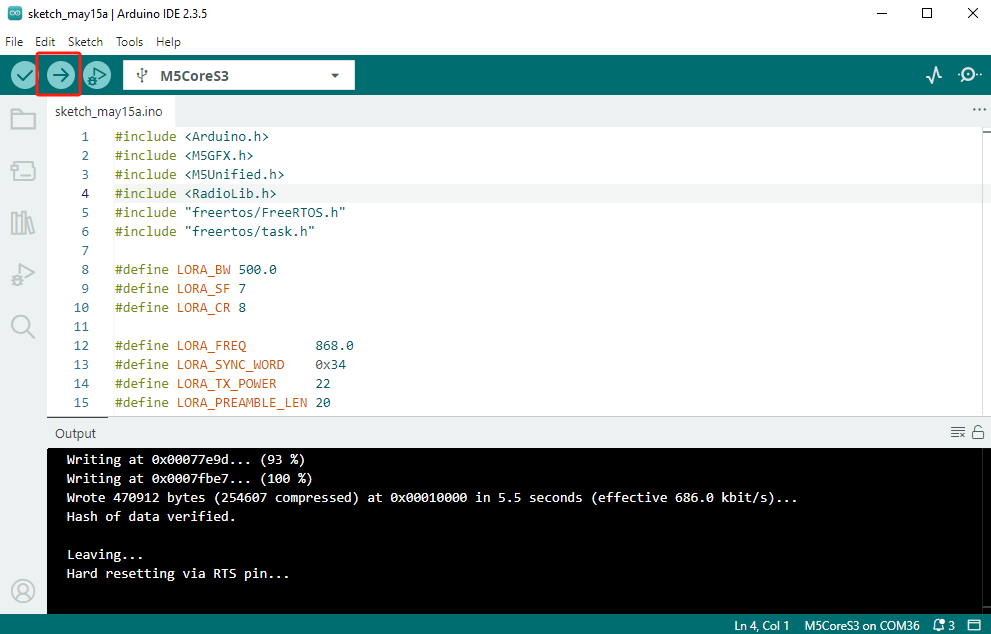
- 2.选中设备端口, 点击Arduino IDE左上角编译上传按钮, 等待程序完成编译并上传至设备。
4.LoRa收发测试
2 组 CoreS3 + Module LoRa868 v1.2 设备分别烧录相同的 LoRa 收发测试程序后,触摸屏幕进行数据发送测试。