


Arduino 上手教程
2. 设备开发 & 案例程序
3. M5Unified
4. M5GFX
5. 拓展模块
Unit
Atomic
Tab5
IoT
Module Gateway H2 Arduino 使用教程
本教程将介绍如何使用Module Gateway H2运行Zigbee与Thread Arduino案例程序, 实现网络通信。
板管理版本要求
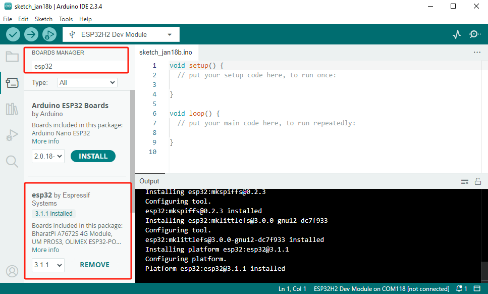
Zigbee与Thread的功能需使用较新的ESP32 Arduino板管理版本, 同时需进行一些分区表配置操作, 本教程将基于v3.1.1版本实现。请参考以下安装教程进行操作与配置。
1.准备工作
- 1.环境配置: 参考Arduino IDE上手教程完成IDE安装。
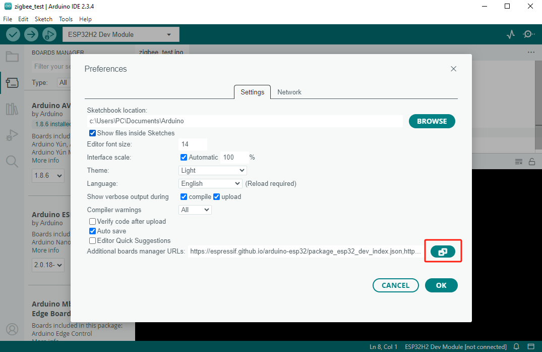
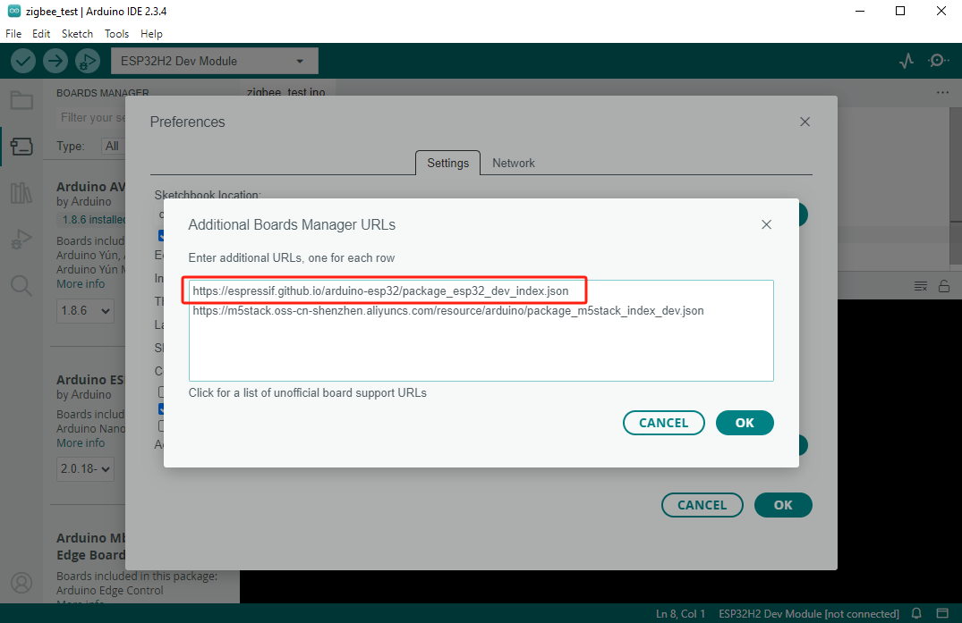
在首选项窗口中,找到"附加开发板管理器网址"的输入框,并添加以下URL:
https://espressif.github.io/arduino-esp32/package_esp32_dev_index.json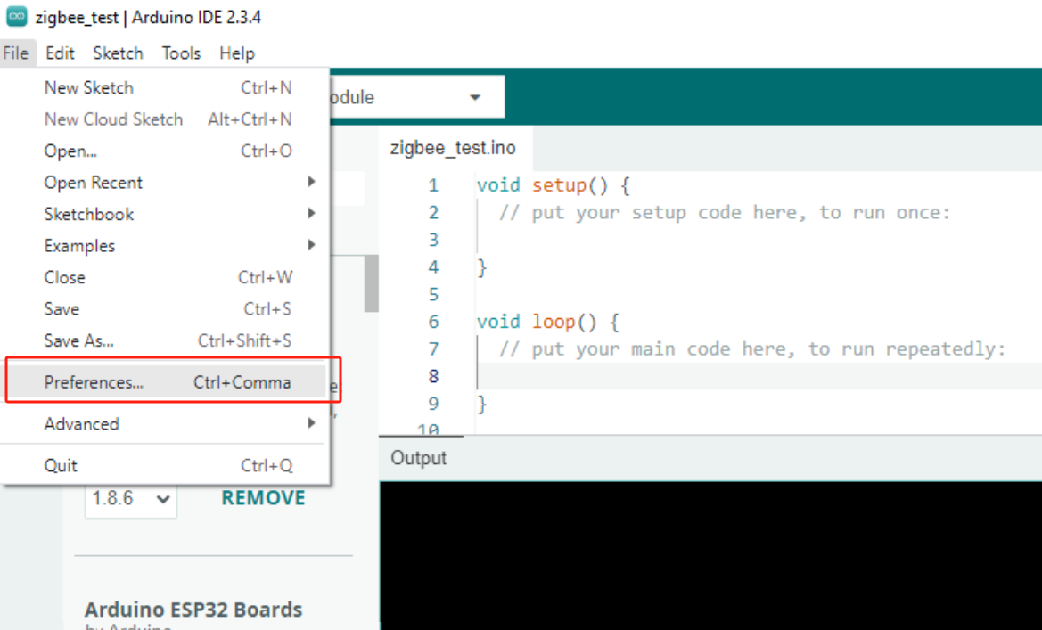
在板管理中搜索ESP32, 并完成板管理安装。注:该步骤需要下载安装较多工具链, 如遇下载失败情况, 可尝试更换网络环境或配置代理。
2.使用到的驱动库:
3.使用到的硬件产品:
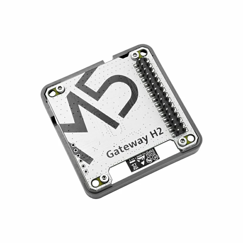
Module Gateway H2
本教程将使用到
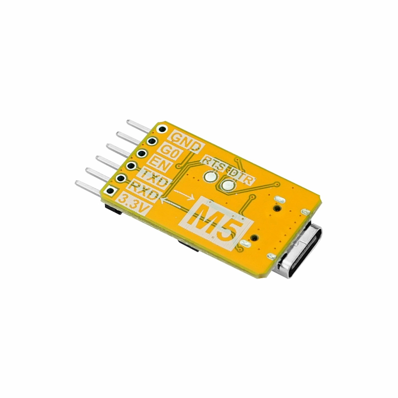
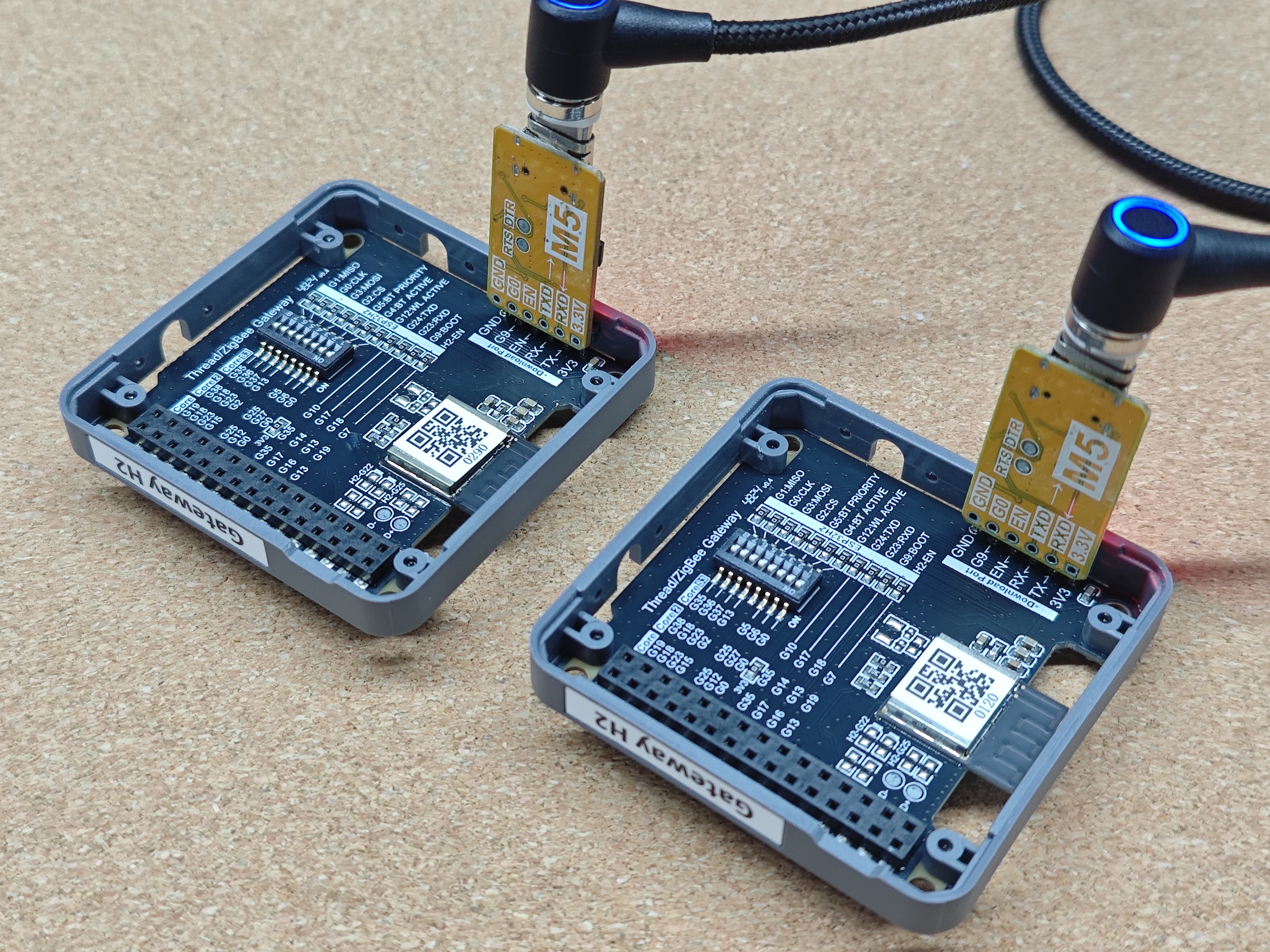
Module Gateway H2+ESP32 Downloader进行演示。Module Gateway H2的核心模组使用了ESP32-H2-MINI-1-N2, 其具备作为独立工作的能力, 本教程将直接通过ESP32 Downloader直接烧录案例程序至Module Gateway H2中, 并将其作为独立设备使用。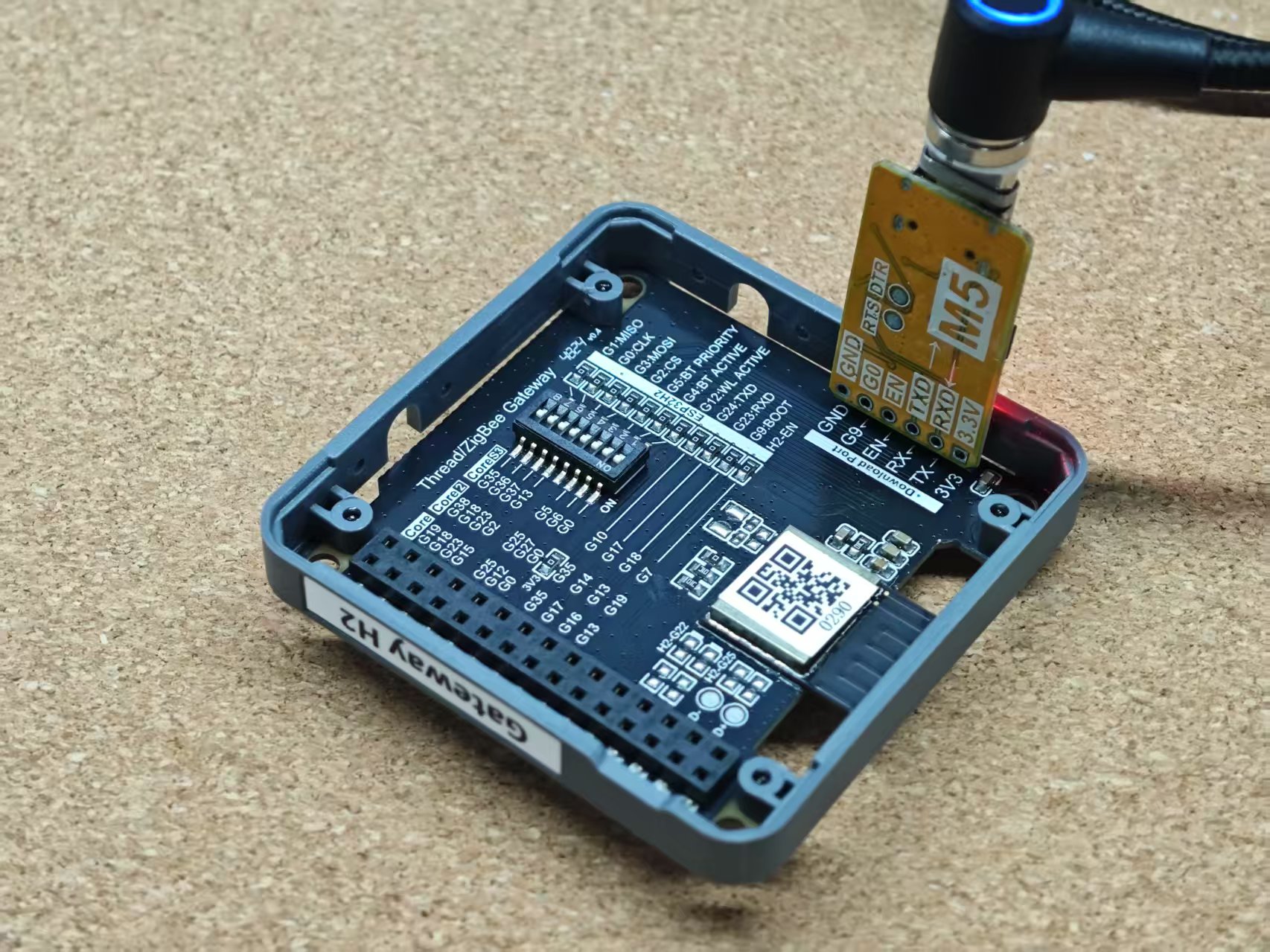
2.Custom分区表
Partitions
Module Gateway H2的核心模组使用了2MB Flash版本的
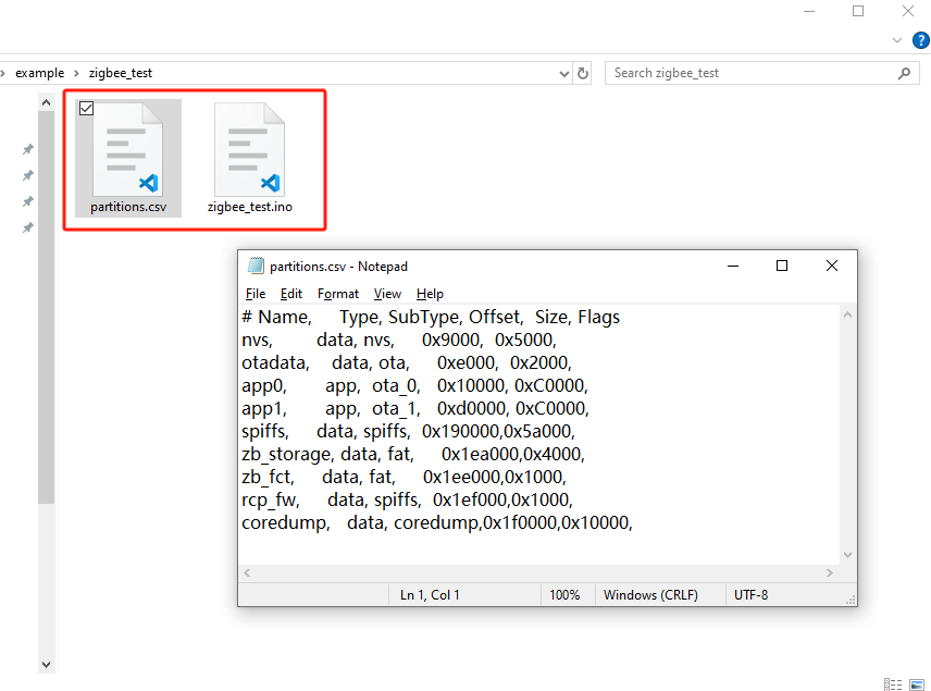
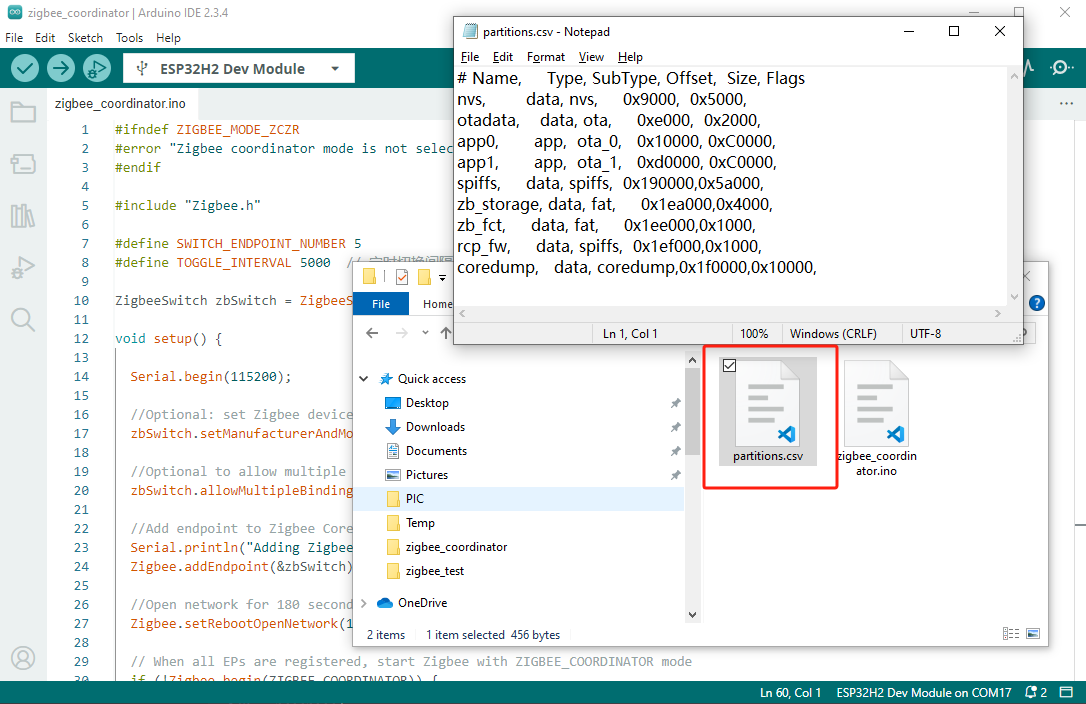
ESP32-H2-MINI-1-N2, 因此在程序编译前, 我们需要对使用的分区表进行调整。由于默认的分区表选项并没有提供2MB版本的配置, 因此我们将使用custom选项。当启用该选项时, 需提供自定义的分区表文件, 使用时将其放置工程文件(.ino)同级目录下, 并将其命名为partitions.csv, 以便编译时能够正确加载该分区表。下方不同案例的案例程序可能会使用到不同的分区表, 请参考案例的具体说明进行操作。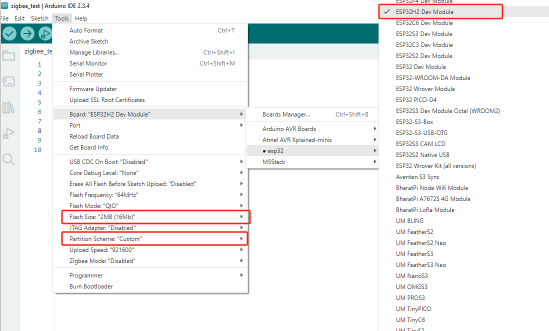
3.Zigbee
Coordinator & End Device
本案例将用到2x Module Gateway H2, 分别烧录程序Zigbee OnOff Switch(Coordinator)与Zigbee OnOff Light(End Device)。
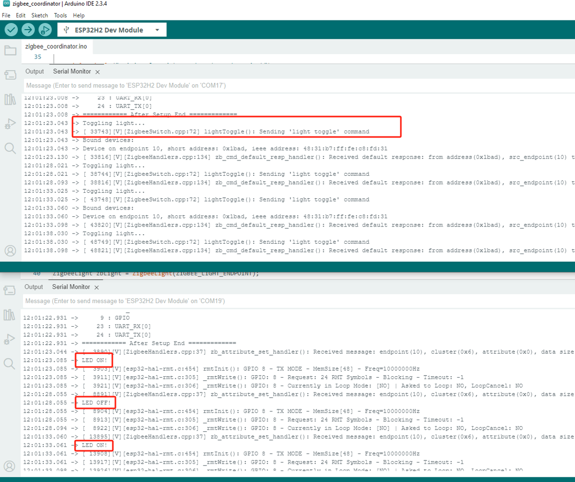
协调器(Coordinator)启动后会自动创建网络并等待设备加入, 完成设备加入与绑定后将间隔发送开关灯指令。
终端设备(End Device)则启动后可接受来自Coordinator的控制指令, 并打印当前LED状态。
协调器(Coordinator)启动后会自动创建网络并等待设备加入, 完成设备加入与绑定后将间隔发送开关灯指令。
终端设备(End Device)则启动后可接受来自Coordinator的控制指令, 并打印当前LED状态。
Zigbee OnOff Light(End Device)
Arduino IDE Tools菜单配置:
- 选择正确的开发板:
Tools -> Board: ESP32H2 Dev Module - 选择开启擦除:
Tools -> Erase All Flash Before Sketch Upload: Enable(不开启可能导致连接失败) - 选择flash大小:
Tools -> Flash Size: 2MB - 选择终端设备模式:
Tools -> Zigbee mode: Zigbee ED (end device) - 选择 Zigbee 分区方案:
Tools -> Partition Scheme: custom
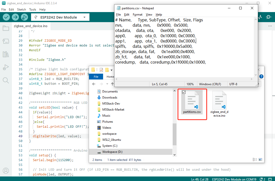
Zigbee End Device分区表配置
以下Zigbee案例程序将使用该分区表配置进行编译, 请在编译程序前启用
custom分区表选项, 并复制以下分区表保存为partitions.csv文件, 放置到工程文件(.ino)同级目录下。- Zigbee 2MB with spiffs
# Name,     Type, SubType, Offset,  Size, Flags
nvs,        data, nvs,     0x9000,  0x5000,
otadata,    data, ota,     0xe000,  0x2000,
app0,       app,  ota_0,   0x10000, 0xC0000,
app1,       app,  ota_1,   0xd0000, 0xC0000,
spiffs,     data, spiffs,  0x190000,0x5a000,
zb_storage, data, fat,     0x1ea000,0x4000,
zb_fct,     data, fat,     0x1ee000,0x1000,
coredump,   data, coredump,0x1f0000,0x10000,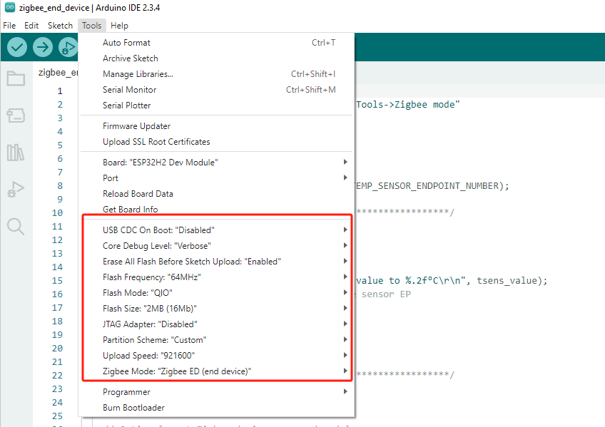
cpp
1 2 3 4 5 6 7 8 9 10 11 12 13 14 15 16 17 18 19 20 21 22 23 24 25 26 27 28 29 30 31 32 33 34 35 36 37 38 39 40 41 42 43 44 45 46 47 48 49 50 51 52 53 54 55 56 57 58 59 60 61 62 63 64 65 66 67 68 69 70 71 72 73 74 75 76 77 78
#ifndef ZIGBEE_MODE_ED
#error "Zigbee end device mode is not selected in Tools->Zigbee mode"
#endif

#include "Zigbee.h"

/* Zigbee light bulb configuration */
#define ZIGBEE_LIGHT_ENDPOINT 10
uint8_t led = RGB_BUILTIN;
uint8_t button = BOOT_PIN;

ZigbeeLight zbLight = ZigbeeLight(ZIGBEE_LIGHT_ENDPOINT);

/********************* RGB LED functions **************************/
void setLED(bool value) {
  if(value){
    Serial.println("LED ON!");
  }else{
    Serial.println("LED OFF!");
  }
  digitalWrite(led, value);
}

/********************* Arduino functions **************************/
void setup() {
  Serial.begin(115200);

  // Init LED and turn it OFF (if LED_PIN == RGB_BUILTIN, the rgbLedWrite() will be used under the hood)
  pinMode(led, OUTPUT);
  digitalWrite(led, LOW);

  // Init button for factory reset
  pinMode(button, INPUT_PULLUP);

  //Optional: set Zigbee device name and model
  zbLight.setManufacturerAndModel("Espressif", "ZBLightBulb");

  // Set callback function for light change
  zbLight.onLightChange(setLED);

  //Add endpoint to Zigbee Core
  Serial.println("Adding ZigbeeLight endpoint to Zigbee Core");
  Zigbee.addEndpoint(&zbLight);

  // When all EPs are registered, start Zigbee. By default acts as ZIGBEE_END_DEVICE
  if (!Zigbee.begin()) {
    Serial.println("Zigbee failed to start!");
    Serial.println("Rebooting...");
    ESP.restart();
  }
  Serial.println("Connecting to network");
  while (!Zigbee.connected()) {
    Serial.print(".");
    delay(100);
  }
  Serial.println();
}

void loop() {
  // Checking button for factory reset
  if (digitalRead(button) == LOW) {  // Push button pressed
    // Key debounce handling
    delay(100);
    int startTime = millis();
    while (digitalRead(button) == LOW) {
      delay(50);
      if ((millis() - startTime) > 3000) {
        // If key pressed for more than 3secs, factory reset Zigbee and reboot
        Serial.println("Resetting Zigbee to factory and rebooting in 1s.");
        delay(1000);
        Zigbee.factoryReset();
      }
    }
    // Toggle light by pressing the button
    zbLight.setLight(!zbLight.getLightState());
  }
  delay(100);
}Zigbee OnOff Switch(Coordinator)
Arduino IDE Tools菜单配置:
- 选择正确的开发板:
Tools -> Board: ESP32H2 Dev Module - 选择开启擦除:
Tools -> Erase All Flash Before Sketch Upload: Enable(不开启可能导致连接失败) - 选择flash大小:
Tools -> Flash Size: 2MB - 选择协调器模式:
Tools -> Zigbee mode: Zigbee ZCZR (coordinator/router) - 选择 Zigbee 分区方案:
Tools -> Partition Scheme: custom
Zigbee Coordinator分区表配置
以下Zigbee案例程序将使用该分区表配置进行编译, 请在编译程序前启用
custom分区表选项, 并复制以下分区表保存为partitions.csv文件, 放置到工程文件(.ino)同级目录下。- Zigbee ZCZR 2MB with spiffs
# Name,     Type, SubType, Offset,  Size, Flags
nvs,        data, nvs,     0x9000,  0x5000,
otadata,    data, ota,     0xe000,  0x2000,
app0,       app,  ota_0,   0x10000, 0xC0000,
app1,       app,  ota_1,   0xd0000, 0xC0000,
spiffs,     data, spiffs,  0x190000,0x5a000,
zb_storage, data, fat,     0x1ea000,0x4000,
zb_fct,     data, fat,     0x1ee000,0x1000,
rcp_fw,     data, spiffs,  0x1ef000,0x1000,
coredump,   data, coredump,0x1f0000,0x10000,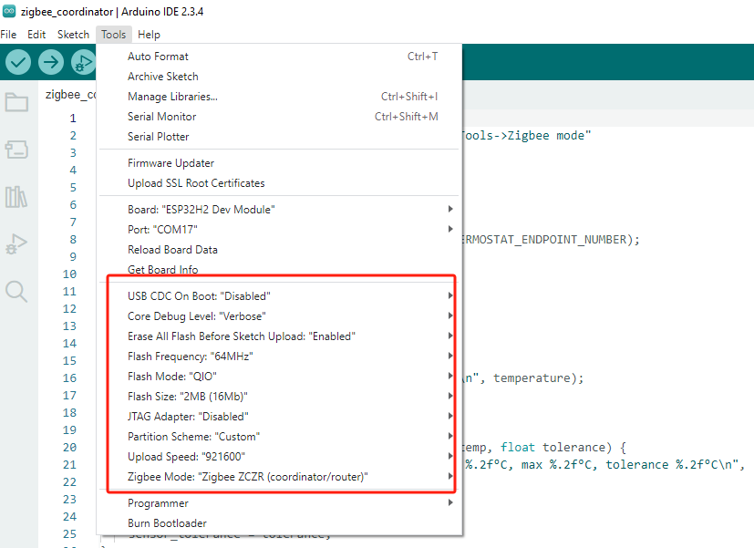
cpp
1 2 3 4 5 6 7 8 9 10 11 12 13 14 15 16 17 18 19 20 21 22 23 24 25 26 27 28 29 30 31 32 33 34 35 36 37 38 39 40 41 42 43 44 45 46 47 48 49 50 51 52 53 54 55 56 57 58 59 60 61 62 63 64 65 66 67 68 69 70 71 72 73 74 75 76 77 78 79 80 81
#ifndef ZIGBEE_MODE_ZCZR
#error "Zigbee coordinator mode is not selected in Tools->Zigbee mode"
#endif
#include "Zigbee.h"
#define SWITCH_ENDPOINT_NUMBER 5
#define TOGGLE_INTERVAL 5000 // 定时切换间隔(毫秒)
ZigbeeSwitch zbSwitch = ZigbeeSwitch(SWITCH_ENDPOINT_NUMBER);
void setup() {
Serial.begin(115200);
//Optional: set Zigbee device name and model
zbSwitch.setManufacturerAndModel("Espressif", "ZigbeeSwitch");
//Optional to allow multiple light to bind to the switch
zbSwitch.allowMultipleBinding(true);
//Add endpoint to Zigbee Core
Serial.println("Adding ZigbeeSwitch endpoint to Zigbee Core");
Zigbee.addEndpoint(&zbSwitch);
//Open network for 180 seconds after boot
Zigbee.setRebootOpenNetwork(180);
// When all EPs are registered, start Zigbee with ZIGBEE_COORDINATOR mode
if (!Zigbee.begin(ZIGBEE_COORDINATOR)) {
Serial.println("Zigbee failed to start!");
Serial.println("Rebooting...");
ESP.restart();
}
Serial.println("Waiting for Light to bound to the switch");
//Wait for switch to bound to a light:
while (!zbSwitch.bound()) {
Serial.printf(".");
delay(500);
}
// Optional: List all bound devices and read manufacturer and model name
std::list<zb_device_params_t *> boundLights = zbSwitch.getBoundDevices();
for (const auto &device : boundLights) {
Serial.printf("Device on endpoint %d, short address: 0x%x\r\n", device->endpoint, device->short_addr);
Serial.printf(
"IEEE Address: %02X:%02X:%02X:%02X:%02X:%02X:%02X:%02X\r\n", device->ieee_addr[7], device->ieee_addr[6], device->ieee_addr[5], device->ieee_addr[4],
device->ieee_addr[3], device->ieee_addr[2], device->ieee_addr[1], device->ieee_addr[0]
);
char *manufacturer = zbSwitch.readManufacturer(device->endpoint, device->short_addr, device->ieee_addr);
char *model = zbSwitch.readModel(device->endpoint, device->short_addr, device->ieee_addr);
if (manufacturer != nullptr) {
Serial.printf("Light manufacturer: %s\r\n", manufacturer);
}
if (model != nullptr) {
Serial.printf("Light model: %s\r\n", model);
}
}
Serial.println();
}
void loop() {
static unsigned long lastToggleTime = 0;
// 每隔一定时间切换灯的状态
if (millis() - lastToggleTime > TOGGLE_INTERVAL) {
lastToggleTime = millis();
Serial.println("Toggling light...");
zbSwitch.lightToggle();
}
// print the bound lights every 10 seconds
static uint32_t lastPrint = 0;
if (millis() - lastPrint > 10000) {
lastPrint = millis();
zbSwitch.printBoundDevices(Serial);
}
}使用步骤
- 1.确保协调器已经运行并创建网络,将OnOff Light代码烧录到终端节点设备。
- 2.设备启动后会自动搜索并加入网络,OnOff Switch将定时发送灯光切换指令。
4.Zigbee Scan Network
Arduino IDE Tools菜单配置:
- 选择正确的开发板:
Tools -> Board: ESP32H2 Dev Module - 选择开启擦除:
Tools -> Erase All Flash Before Sketch Upload: Enable(不开启可能导致连接失败) - 选择flash大小:
Tools -> Flash Size: 2MB - 选择协调器模式:
Tools -> Zigbee mode: Zigbee ZCZR (coordinator/router) - 选择 Zigbee 分区方案:
Tools -> Partition Scheme: custom
Zigbee案例分区表配置
以下Zigbee案例程序将使用该分区表配置进行编译, 请在编译程序前启用
custom分区表选项, 并复制以下分区表保存为partitions.csv文件, 放置到工程文件(.ino)同级目录下。- Zigbee ZCZR 2MB with spiffs
# Name,     Type, SubType, Offset,  Size, Flags
nvs,        data, nvs,     0x9000,  0x5000,
otadata,    data, ota,     0xe000,  0x2000,
app0,       app,  ota_0,   0x10000, 0xC0000,
app1,       app,  ota_1,   0xd0000, 0xC0000,
spiffs,     data, spiffs,  0x190000,0x5a000,
zb_storage, data, fat,     0x1ea000,0x4000,
zb_fct,     data, fat,     0x1ee000,0x1000,
rcp_fw,     data, spiffs,  0x1ef000,0x1000,
coredump, data, coredump,0x1f0000,0x10000,Zigbee Scan Network
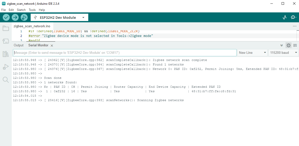
本案例将使用Module Gateway H2实现Zigbee网络扫描, 并打印网络信息至串口。
cpp
1 2 3 4 5 6 7 8 9 10 11 12 13 14 15 16 17 18 19 20 21 22 23 24 25 26 27 28 29 30 31 32 33 34 35 36 37 38 39 40 41 42 43 44 45 46 47 48 49 50 51 52 53 54 55 56 57 58 59 60 61 62 63 64 65 66 67 68 69 70 71 72 73 74 75 76 77 78 79 80 81 82
#if !defined(ZIGBEE_MODE_ED) && !defined(ZIGBEE_MODE_ZCZR)
#error "Zigbee device mode is not selected in Tools->Zigbee mode"
#endif

#include "Zigbee.h"

#ifdef ZIGBEE_MODE_ZCZR
zigbee_role_t role = ZIGBEE_ROUTER;  // or can be ZIGBEE_COORDINATOR, but it won't scan itself
#else
zigbee_role_t role = ZIGBEE_END_DEVICE;
#endif

void printScannedNetworks(uint16_t networksFound) {
    if (networksFound == 0) {
        Serial.println("No networks found");
    } else {
        zigbee_scan_result_t *scan_result = Zigbee.getScanResult();
        Serial.println("\nScan done");
        Serial.print(networksFound);
        Serial.println(" networks found:");
        Serial.println("Nr | PAN ID | CH | Permit Joining | Router Capacity | End Device Capacity | Extended PAN ID");
        for (int i = 0; i < networksFound; ++i) {
        // Print all available info for each network found
        Serial.printf("%2d", i + 1);
        Serial.print(" | ");
        Serial.printf("0x%04hx", scan_result[i].short_pan_id);
        Serial.print(" | ");
        Serial.printf("%2d", scan_result[i].logic_channel);
        Serial.print(" | ");
        Serial.printf("%-14.14s", scan_result[i].permit_joining ? "Yes" : "No");
        Serial.print(" | ");
        Serial.printf("%-15.15s", scan_result[i].router_capacity ? "Yes" : "No");
        Serial.print(" | ");
        Serial.printf("%-19.19s", scan_result[i].end_device_capacity ? "Yes" : "No");
        Serial.print(" | ");
        Serial.printf(
            "%02x:%02x:%02x:%02x:%02x:%02x:%02x:%02x", scan_result[i].extended_pan_id[7], scan_result[i].extended_pan_id[6], scan_result[i].extended_pan_id[5],
            scan_result[i].extended_pan_id[4], scan_result[i].extended_pan_id[3], scan_result[i].extended_pan_id[2], scan_result[i].extended_pan_id[1],
            scan_result[i].extended_pan_id[0]
        );
        Serial.println();
        delay(10);
        }
        Serial.println("");
        // Delete the scan result to free memory for code below.
        Zigbee.scanDelete();
    }
}

void setup() {
    Serial.begin(115200);

    // Initialize Zigbee stack without any EPs just for scanning
    if (!Zigbee.begin(role)) {
        Serial.println("Zigbee failed to start!");
        Serial.println("Rebooting...");
        ESP.restart();
    }

    Serial.println("Setup done, starting Zigbee network scan...");
    // Start Zigbee Network Scan with default parameters (all channels, scan time 5)
    Zigbee.scanNetworks();
}

void loop() {
    // check Zigbee Network Scan process
    int16_t ZigbeeScanStatus = Zigbee.scanComplete();
    if (ZigbeeScanStatus < 0) {  // it is busy scanning or got an error
        if (ZigbeeScanStatus == ZB_SCAN_FAILED) {
        Serial.println("Zigbee scan has failed. Starting again.");
        delay(1000);
        Zigbee.scanNetworks();
        }
        delay(100);
        // other option is status ZB_SCAN_RUNNING - just wait.
    } else {  // Found Zero or more Wireless Networks
        printScannedNetworks(ZigbeeScanStatus);
        delay(1000);
        Zigbee.scanNetworks();  // start over...
    }
    // Loop can do something else...
}使用步骤
- 1.设备启动后自动开始扫描,若周边存在活跃的Zigbee网络, 每次扫描完成后将扫描当前显示结果,并自动开始下一轮扫描。
5.OpenThread
案例程序
在菜单路径
File -> Examples -> OpenThread, 可查看OpenThread相关案例程序。程序编译前请参考下方分区表配置等配置信息。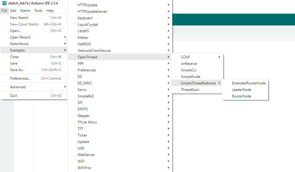
Arduino IDE Tools菜单配置:
- 选择正确的开发板:
Tools -> Board: ESP32H2 Dev Module - 选择开启擦除:
Tools -> Erase All Flash Before Sketch Upload: Enable(不开启可能导致连接失败) - 选择flash大小:
Tools -> Flash Size: 2MB - 选择 Zigbee 分区方案:
Tools -> Partition Scheme: Minimal SPIFFS (1.3MB APP/700K SPIFFS)
