Home Assistant
Media Player
Expansion
Sensor
Unit 4Relay Home Assistant Integration
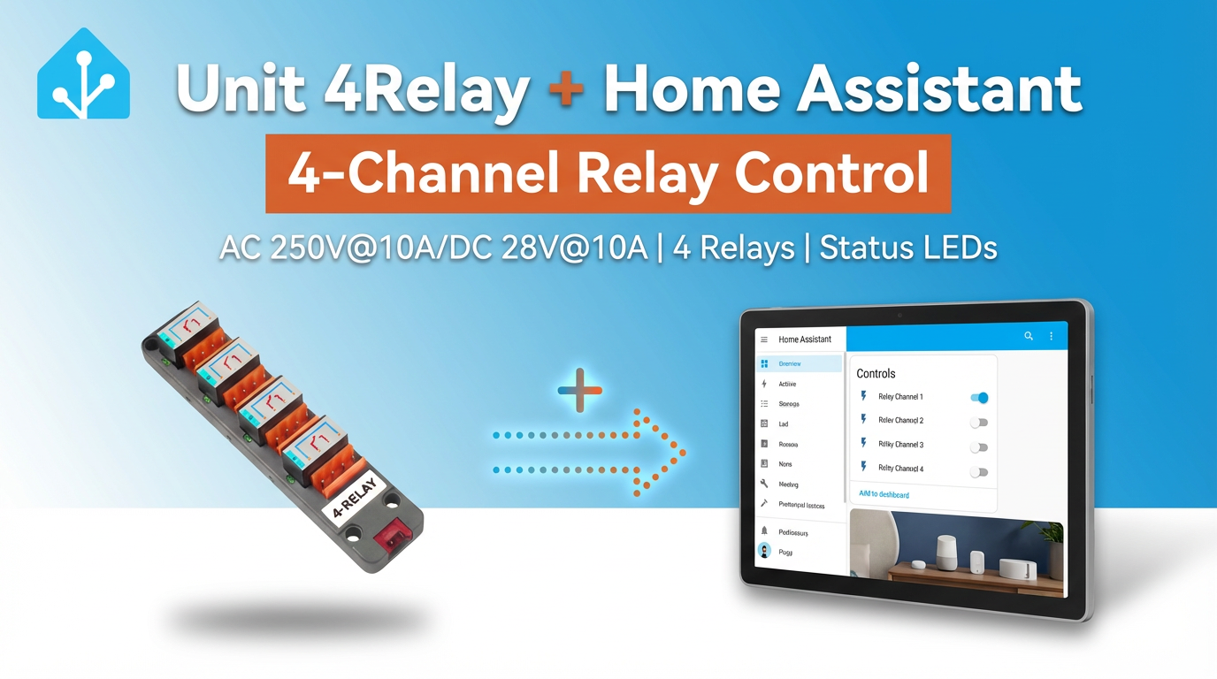
This chapter describes the configuration and practical steps for integrating Unit 4Relay into Home Assistant.
1. Hardware Products
2. Modify Configuration
Relay Configuration
Enable the I²C component in the ESPHome configuration:
# Example configuration entry for ESP32
i2c:
  sda: GPIOXX
  scl: GPIOXX
scan: trueThe GPIO pins vary depending on the controller used. For example, when using Atom Lite as the controller:
# I2C Bus on Grove Port (HY2.0-4P)
i2c:
  sda: GPIO26
scl: GPIO32Unit 4Relay configuration example:
Because Unit 4Relay is controlled by its built-in STM32, external_component is required for I2C communication control.
external_components:
  - source: github://m5stack/esphome-yaml/components@main
    components: unit4relay
    refresh: 0s

unit4relay:

switch:
  - platform: unit4relay
    relay_1:
      name: "Relay Channel 1"
      restore_mode: RESTORE_DEFAULT_OFF
    relay_2:
      name: "Relay Channel 2"
      restore_mode: RESTORE_DEFAULT_OFF
    relay_3:
      name: "Relay Channel 3"
      restore_mode: RESTORE_DEFAULT_OFF
    relay_4:
      name: "Relay Channel 4"
      restore_mode: RESTORE_DEFAULT_OFF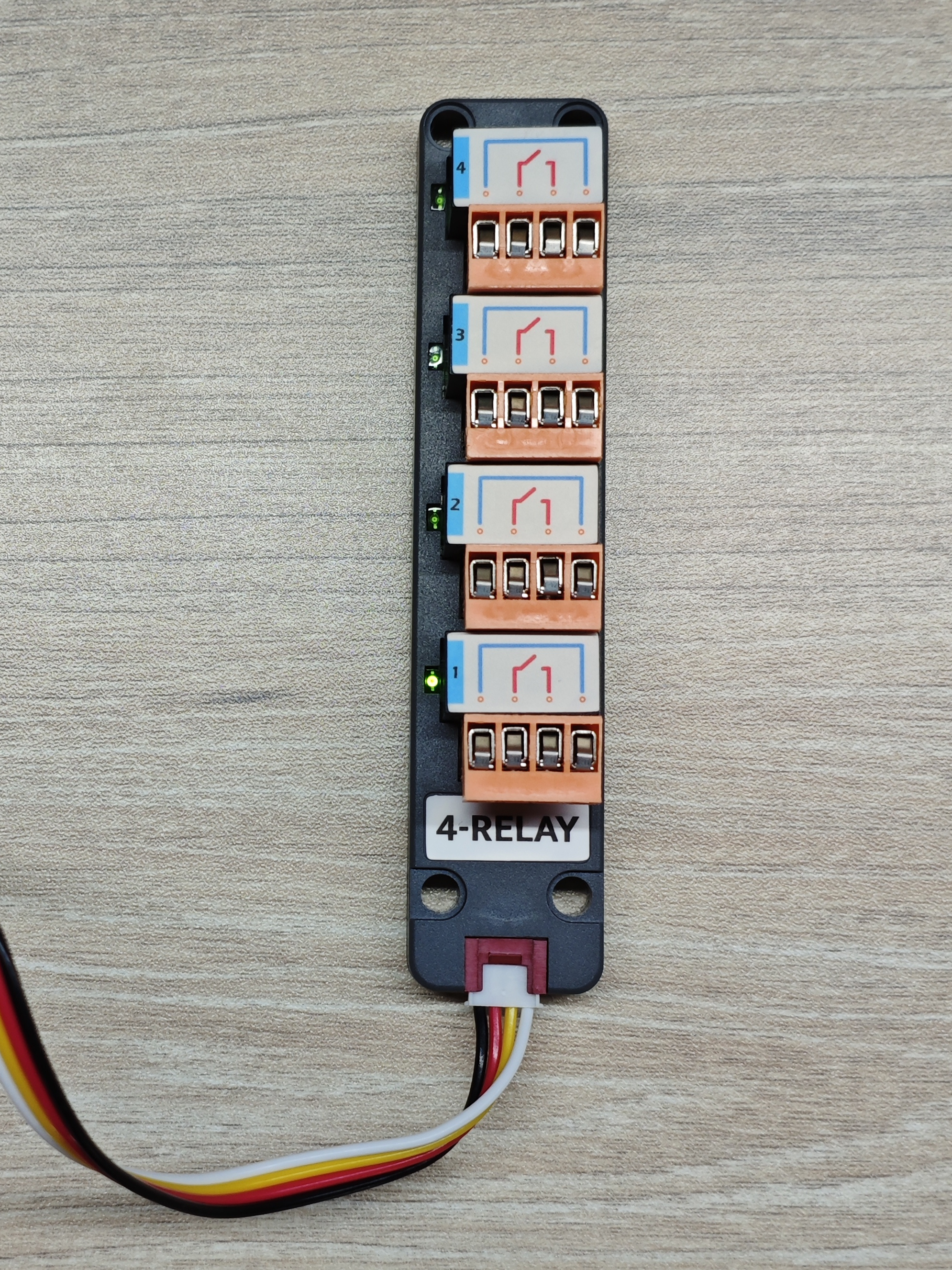
The default indicator control is used here. When a channel switch is turned on, the corresponding LED lights up.
Configurable Options
Component
# Example configuration entry
unit4relay:- id (Optional, ID): Sets an ID for the Unit 4Relay component.
Switch
relay_1 (Optional): Relay switch for channel 1. The default is
false(off). All other configuration options supported by Switch are also available.relay_2 (Optional): Relay switch for channel 2. The default is
false(off). All other configuration options supported by Switch are also available.relay_3 (Optional): Relay switch for channel 3. The default is
false(off). All other configuration options supported by Switch are also available.relay_4 (Optional): Relay switch for channel 4. The default is
false(off). All other configuration options supported by Switch are also available.
3. Getting Started
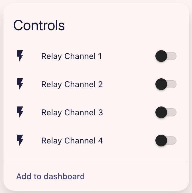
After adding the device to the Dashboard, you can control the relays on and off in Home Assistant.