Home Assistant
Voice Assistant
Kit
Expansion
Sensor
Chain DualKey Home Assistant Integration
This tutorial will introduce how to integrate the Chain DualKey programmable dual-key development board into Home Assistant to achieve button and expansion module control.
Preparation
- Home Assistant host.
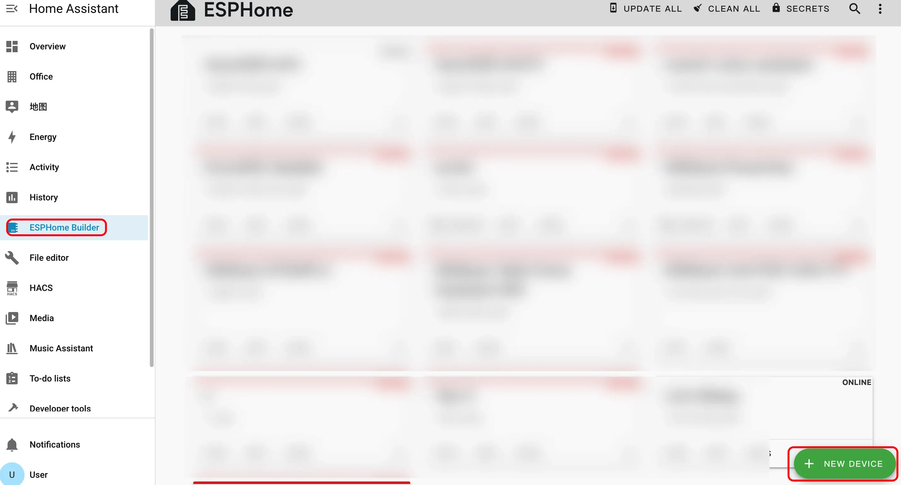
- Install and enable ESPHome Builder in Home Assistant.
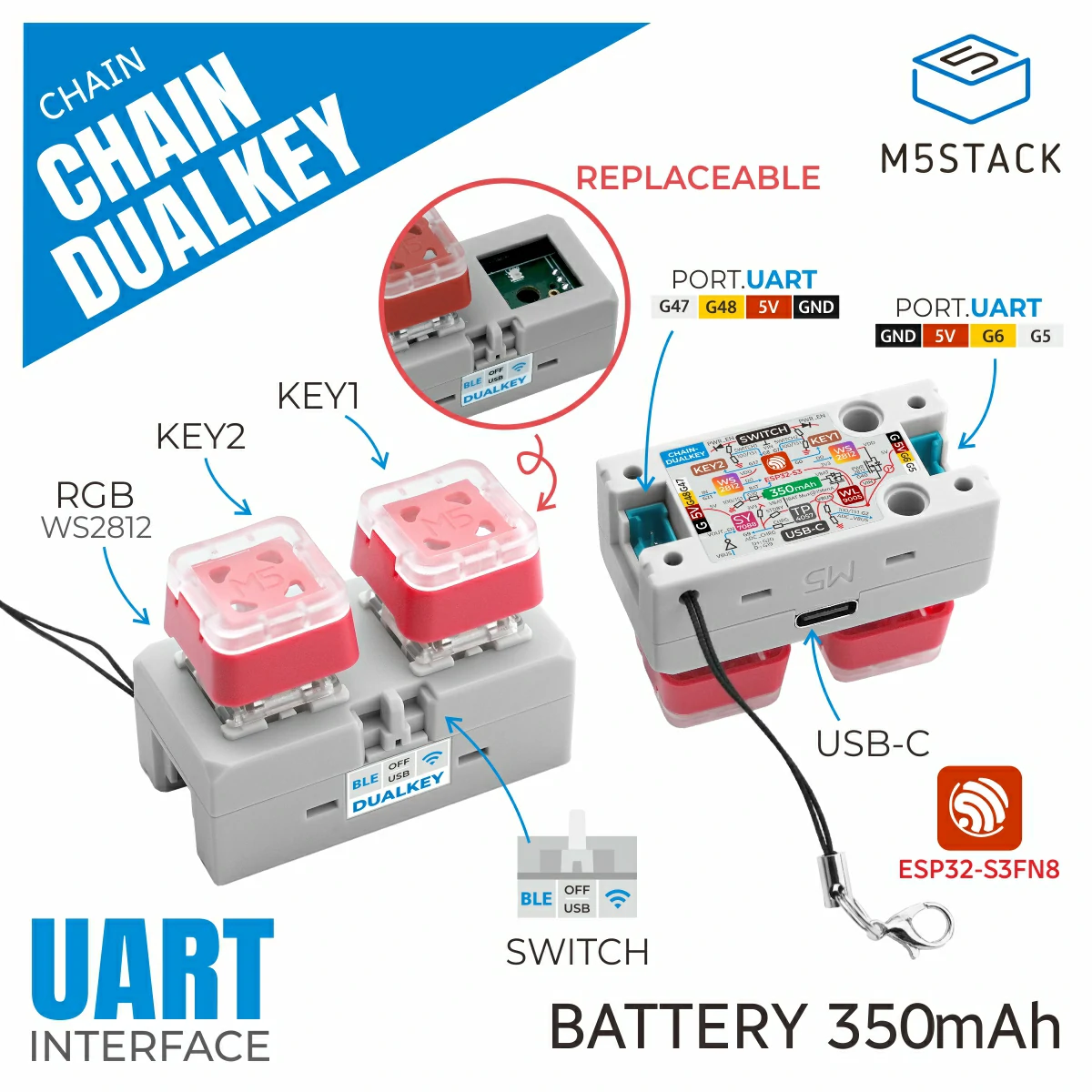
- Chain DualKey
- Chain Angel
- Chain Encoder
- Chain Key
- Chain Joystick
- Chain Tof
Note
In this tutorial, the firmware is compiled and uploaded under ESPHome 2025.1.2. If you encounter compilation/upload issues, please consider switching ESPHome to this version.
Create Device
- Create a new device. Click the green button in the bottom right corner to create the device.
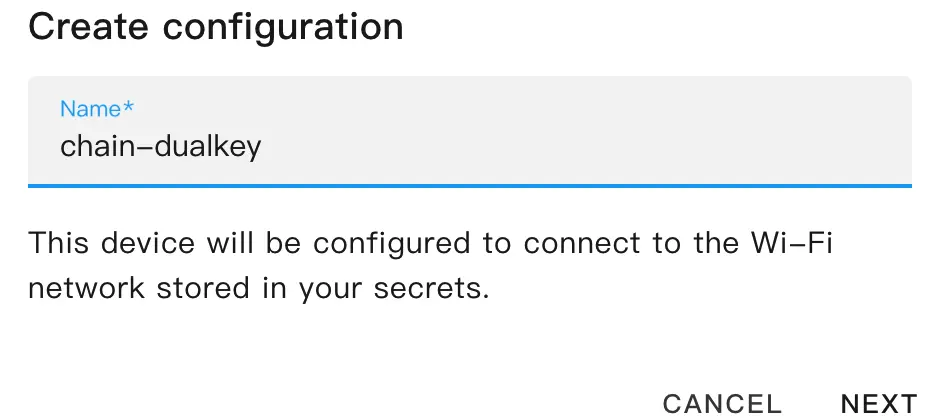
- Create device name.
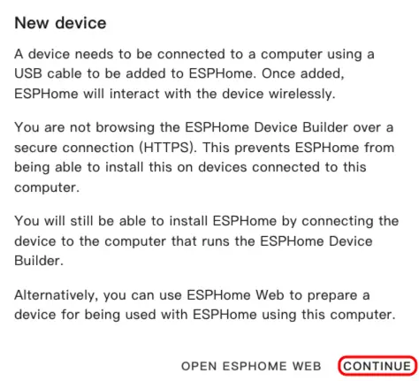
- Click
CONTINUE.
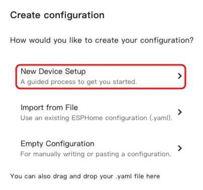
- Click
New Device Setup.
- Enter the device name and click
NEXT.
- Select device type.
- Click
ESP32-S3.

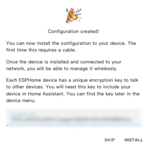
- Click
SKIP.
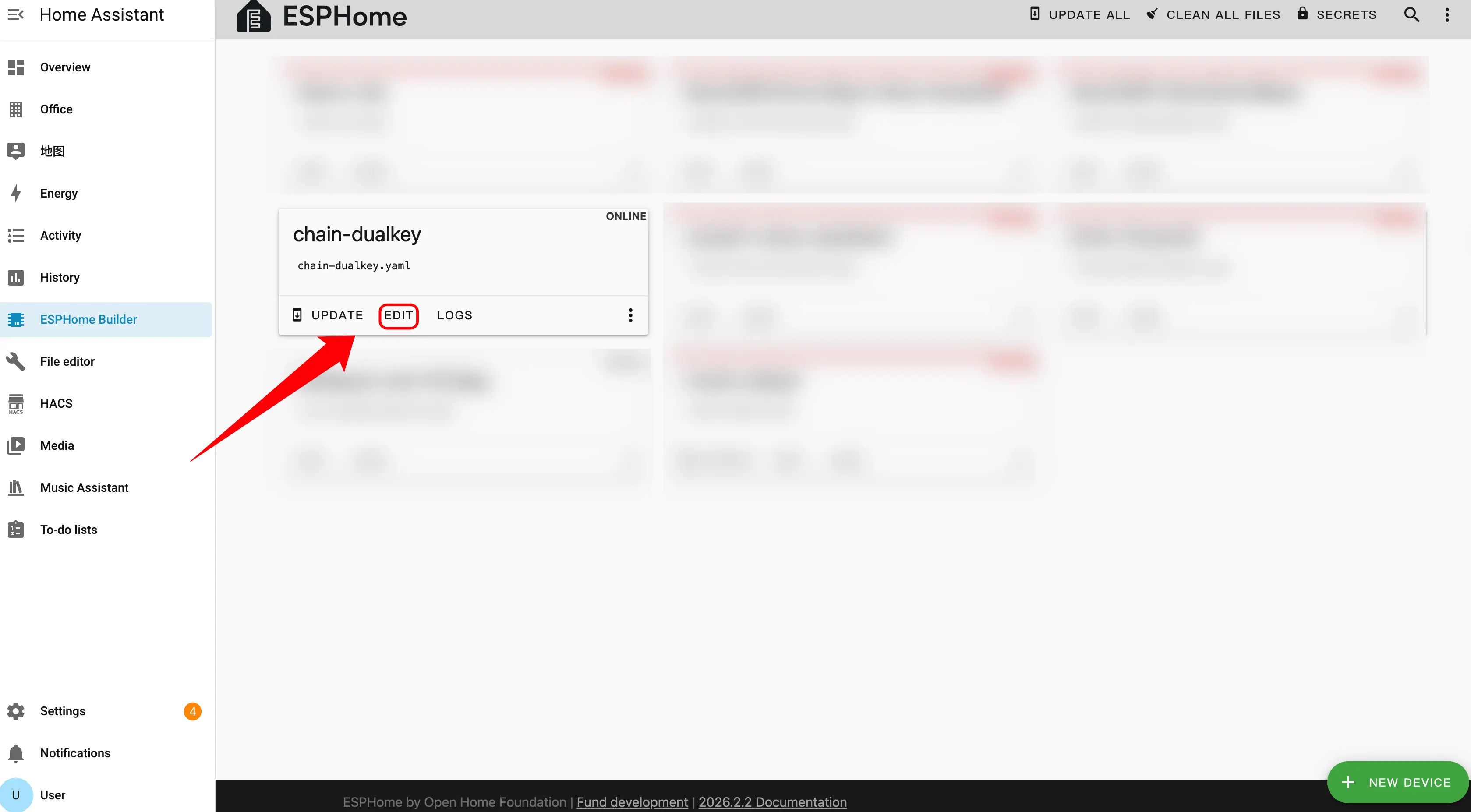
- Edit YAML file. Click
EDIT; we can customize device functions through the YAML file.
Device Configuration
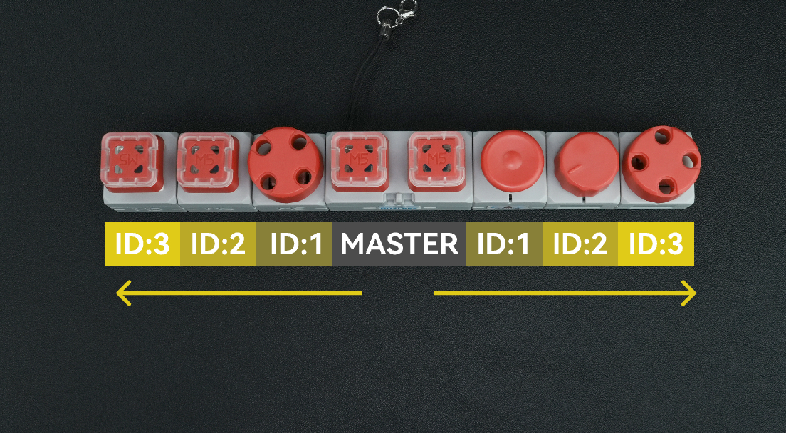
Master serves as the system's main controller. When connecting expansion sensors, it is necessary to correctly distinguish the connection direction and ID numbering sequence.
Direction Selection
Depending on which side of the Master the expansion sensor is connected to, select the corresponding uart_id:
- Connected to the Master's left side → Use
chain_uart_left. - Connected to the Master's right side → Use
chain_uart_right.
ID Numbering Rules
chain_id indicates the position of the expansion sensor relative to the Master:
- Numbering starts from the module closest to the Master.
- IDs increase sequentially (ID:1 → ID:2 → ID:3 …).
- The left and right sides are numbered independently.
- Refer to the image above to determine the correct sequence.
Configuration Example
uart_id:chain_uart_left.chain_id:1.
Chain DualKey
uart:
  - id: chain_uart_right
    tx_pin: GPIO6
    rx_pin: GPIO5
    baud_rate: 115200

  - id: chain_uart_left
    tx_pin: GPIO48
    rx_pin: GPIO47
    baud_rate: 115200

sensor:
  - platform: adc
    pin: GPIO10
    name: "ADC_BAT"
    update_interval: 1s

  - platform: adc
    pin: GPIO2
    name: "ADC_VBUS"
    update_interval: 1s

  - platform: adc
    pin: GPIO9
    name: "ADC_CHARGE"
    update_interval: 1s

output:
  - platform: gpio
    id: pwr_en
    pin: GPIO40

light:
  - platform: esp32_rmt_led_strip
    id: key_light_raw
    internal: true
    pin: GPIO21
    num_leds: 2
    chipset: ws2812
    rgb_order: GRB
    restore_mode: ALWAYS_OFF

  - platform: partition
    name: "Key Light 1"
    id: key_light_1
    segments:
      - id: key_light_raw
        from: 0
        to: 0

  - platform: partition
    name: "Key Light 2"
    id: key_light_2
    segments:
      - id: key_light_raw
        from: 1
        to: 1

binary_sensor:
  - platform: gpio
    name: "KEY_2"
    pin:
      number: GPIO17
      inverted: true
      mode: INPUT_PULLUP
    filters:
      - delayed_on: 10ms
      - delayed_off: 10ms

    on_press:
      - light.turn_on:
          id: key_light_2
          transition_length: 0ms

    on_release:
      - light.turn_off: key_light_2

  - platform: gpio
    name: "KEY_1"
    pin:
      number: GPIO0
      inverted: true
      mode: INPUT_PULLUP
    filters:
      - delayed_on: 10ms
      - delayed_off: 10ms

    on_press:
      - light.turn_on:
          id: key_light_1
          transition_length: 0ms

    on_release:
      - light.turn_off: key_light_1

  - platform: gpio
    name: "SWITCH_1"
    pin:
      number: GPIO7
      mode: INPUT

  - platform: gpio
    name: "SWITCH_2"
    pin:
      number: GPIO8
mode: INPUTChain Key
external_components:
  - source: github://m5stack/esphome-yaml/components
    components: [m5stack_chain_key]
    refresh: 0s

binary_sensor:
  - platform: m5stack_chain_key
    id: chain_key_1
    name: "Chain Key Button"
    uart_id: xx
    chain_id: xx
    update_interval: 50ms

output:
  - platform: m5stack_chain_key
    id: chain_key_rgb_r
    chain_key_id: chain_key_1
    channel: rgb_red

  - platform: m5stack_chain_key
    id: chain_key_rgb_g
    chain_key_id: chain_key_1
    channel: rgb_green

  - platform: m5stack_chain_key
    id: chain_key_rgb_b
    chain_key_id: chain_key_1
    channel: rgb_blue

light:
  - platform: rgb
    name: "Key RGB"
    red: chain_key_rgb_r
    green: chain_key_rgb_g
blue: chain_key_rgb_bChain Angle
external_components:
  - source: github://m5stack/esphome-yaml/components
    components: [m5stack_chain_angle]
    refresh: 0s

sensor:
  - platform: m5stack_chain_angle
    id: chain_angle_1
    name: "Chain Angle"
    uart_id: xx
    chain_id: xx
    update_interval: 50ms

output:
  - platform: m5stack_chain_angle
    id: chain_angle_rgb_r
    chain_angle_id: chain_angle_1
    channel: rgb_red

  - platform: m5stack_chain_angle
    id: chain_angle_rgb_g
    chain_angle_id: chain_angle_1
    channel: rgb_green

  - platform: m5stack_chain_angle
    id: chain_angle_rgb_b
    chain_angle_id: chain_angle_1
    channel: rgb_blue

light:
  - platform: rgb
    name: "Angle RGB"
    red: chain_angle_rgb_r
    green: chain_angle_rgb_g
blue: chain_angle_rgb_bChain Encoder
external_components:
  - source: github://m5stack/esphome-yaml/components
    components: [m5stack_chain_encoder]
    refresh: 0s

sensor:
  - platform: m5stack_chain_encoder
    id: chain_encoder_1
    name: "Chain Encoder"
    uart_id: xx
    chain_id: xx
    update_interval: 100ms

output:
  - platform: m5stack_chain_encoder
    id: chain_encoder_rgb_r
    chain_encoder_id: chain_encoder_1
    channel: rgb_red

  - platform: m5stack_chain_encoder
    id: chain_encoder_rgb_g
    chain_encoder_id: chain_encoder_1
    channel: rgb_green

  - platform: m5stack_chain_encoder
    id: chain_encoder_rgb_b
    chain_encoder_id: chain_encoder_1
    channel: rgb_blue

light:
  - platform: rgb
    name: "Encoder RGB"
    red: chain_encoder_rgb_r
    green: chain_encoder_rgb_g
    blue: chain_encoder_rgb_b

binary_sensor:
  - platform: m5stack_chain_encoder
    name: "Encoder Button"
chain_encoder_id: chain_encoder_1Chain Joystick
external_components:
  - source: github://m5stack/esphome-yaml/components
    components: [m5stack_chain_joystick]
    refresh: 0s

sensor:
  - platform: m5stack_chain_joystick
    id: chain_joystick_x
    name: "Chain Joystick X"
    uart_id: xx
    chain_id: xx
    axis: x
    update_interval: 50ms

  - platform: m5stack_chain_joystick
    name: "Chain Joystick Y"
    uart_id: xx
    chain_id: xx
    axis: y
    update_interval: 50ms

output:
  - platform: m5stack_chain_joystick
    id: chain_joystick_rgb_r
    chain_joystick_id: chain_joystick_x
    channel: rgb_red

  - platform: m5stack_chain_joystick
    id: chain_joystick_rgb_g
    chain_joystick_id: chain_joystick_x
    channel: rgb_green

  - platform: m5stack_chain_joystick
    id: chain_joystick_rgb_b
    chain_joystick_id: chain_joystick_x
    channel: rgb_blue

light:
  - platform: rgb
    name: "Joystick RGB"
    red: chain_joystick_rgb_r
    green: chain_joystick_rgb_g
    blue: chain_joystick_rgb_b

binary_sensor:
  - platform: m5stack_chain_joystick
    name: "Joystick Button"
chain_joystick_id: chain_joystick_xChain ToF
external_components:
  - source: github://m5stack/esphome-yaml/components
    components: [m5stack_chain_tof]
    refresh: 0s

sensor:
  - platform: m5stack_chain_tof
    id: chain_tof_1
    name: "Chain ToF"
    uart_id: xx
    chain_id: xx
    update_interval: 100ms

output:
  - platform: m5stack_chain_tof
    id: chain_tof_rgb_r
    m5stack_chain_tof_id: chain_tof_1
    channel: rgb_red

  - platform: m5stack_chain_tof
    id: chain_tof_rgb_g
    m5stack_chain_tof_id: chain_tof_1
    channel: rgb_green

  - platform: m5stack_chain_tof
    id: chain_tof_rgb_b
    m5stack_chain_tof_id: chain_tof_1
    channel: rgb_blue

light:
  - platform: rgb
    name: "ToF RGB"
    red: chain_tof_rgb_r
    green: chain_tof_rgb_g
blue: chain_tof_rgb_bExample
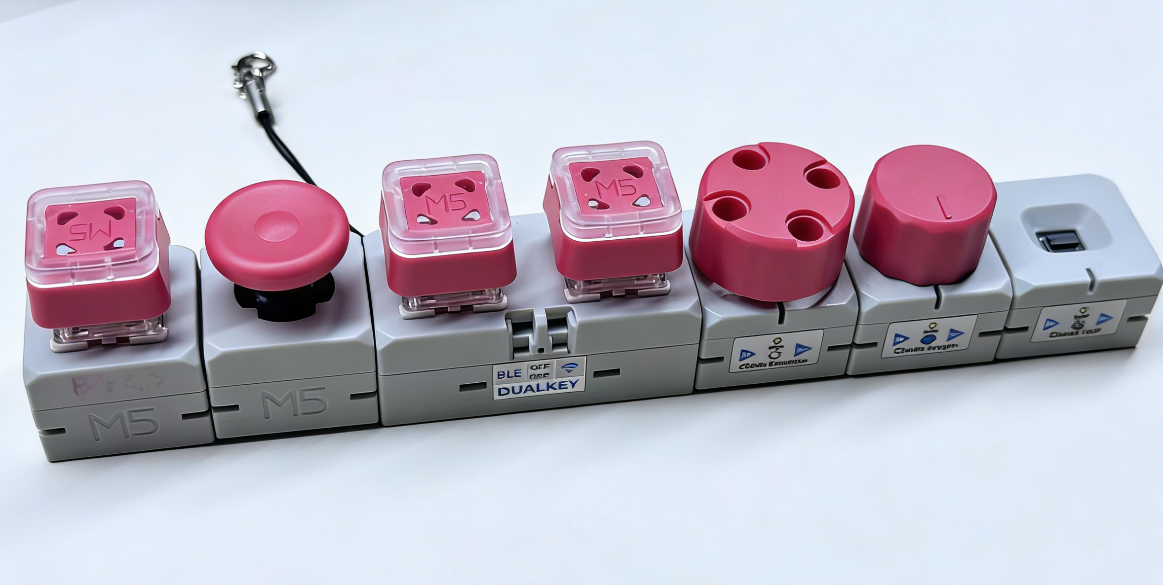
The following code example is configured according to the connection sequence shown in the image above.
External Components
Modules used: Chain Angle, Chain Encoder, Chain ToF, Chain Joystick, Chain Key.
- Add External component. This configuration block is used to introduce all Chain series-related external components. If a module (e.g., Chain Encoder or Chain ToF) is not used, the corresponding entry can be removed from the components list.
external_components:
  - source: github://m5stack/esphome-yaml/components
    components:
      [
        m5stack_chain_angle,
        m5stack_chain_encoder,
        m5stack_chain_tof,
        m5stack_chain_joystick,
        m5stack_chain_key,
      ]
refresh: 0sUART Components
Modules used: The UART bus shared by all Chain series modules on the Master's left/right HY2.0 interfaces.
- Add Uart component. In this example,
chain_uart_rightandchain_uart_leftcorrespond to the HY2.0 interfaces on the right and left sides of the Master, respectively. Subsequent Chain moduleuart_idsettings need to match the actual connection direction.
captive_portal:
uart:
  - id: chain_uart_right
    tx_pin: GPIO6
    rx_pin: GPIO5
    baud_rate: 115200

  - id: chain_uart_left
    tx_pin: GPIO48
    rx_pin: GPIO47
baud_rate: 115200Sensor Components
Modules used: Chain Encoder, Chain Angle, Chain ToF, Chain Joystick (X/Y), DualKey battery-related ADC sensors.
- Add Sensor component. In this example, Chain Encoder (ID 1), Chain Angle (ID 2), and Chain ToF (ID 3) are connected in order on the right side of the Master, and Chain Joystick (ID 1, X/Y axes) is connected on the left side. ADC channels related to battery level (BAT, VBUS, CHARGE) are also enabled as sensors.
sensor:
  - platform: m5stack_chain_encoder
    id: chain_encoder_1
    name: "Encoder"
    uart_id: chain_uart_right
    chain_id: 1
    update_interval: 100ms

  - platform: m5stack_chain_tof
    id: chain_tof_1
    name: "ToF Distance"
    uart_id: chain_uart_right
    chain_id: 3
    update_interval: 100ms

  - platform: m5stack_chain_angle
    id: chain_angle_1
    name: "Angle"
    uart_id: chain_uart_right
    chain_id: 2
    update_interval: 100ms

  - platform: m5stack_chain_joystick
    id: chain_joystick_x
    name: "Joystick X"
    uart_id: chain_uart_left
    chain_id: 1
    axis: x
    update_interval: 100ms

  - platform: m5stack_chain_joystick
    name: "Joystick Y"
    uart_id: chain_uart_left
    chain_id: 1
    axis: y
    update_interval: 100ms

  - platform: adc
    pin: GPIO10
    name: "ADC_BAT"
    update_interval: 1s

  - platform: adc
    pin: GPIO2
    name: "ADC_VBUS"
    update_interval: 1s

  - platform: adc
    pin: GPIO9
    name: "ADC_CHARGE"
update_interval: 1sOutput Components
Modules used: RGB lights of Chain Encoder, Chain Key, Chain Joystick, Chain Angle, Chain ToF, and DualKey power control.
- Add Output component. The
pwr_enGPIO output is used to control power supply to the Chain expansion bus, which usually needs to remain on to ensure that modules connected to the bus can operate normally.
output:
  - platform: gpio
    id: pwr_en
    pin: GPIO40

  - platform: m5stack_chain_encoder
    id: chain_encoder_rgb_r
    chain_encoder_id: chain_encoder_1
    channel: rgb_red

  - platform: m5stack_chain_encoder
    id: chain_encoder_rgb_g
    chain_encoder_id: chain_encoder_1
    channel: rgb_green

  - platform: m5stack_chain_encoder
    id: chain_encoder_rgb_b
    chain_encoder_id: chain_encoder_1
    channel: rgb_blue

  - platform: m5stack_chain_key
    id: chain_key_rgb_r
    chain_key_id: chain_key_1
    channel: rgb_red

  - platform: m5stack_chain_key
    id: chain_key_rgb_g
    chain_key_id: chain_key_1
    channel: rgb_green

  - platform: m5stack_chain_key
    id: chain_key_rgb_b
    chain_key_id: chain_key_1
    channel: rgb_blue

  - platform: m5stack_chain_joystick
    id: chain_joystick_rgb_r
    chain_joystick_id: chain_joystick_x
    channel: rgb_red

  - platform: m5stack_chain_joystick
    id: chain_joystick_rgb_g
    chain_joystick_id: chain_joystick_x
    channel: rgb_green

  - platform: m5stack_chain_joystick
    id: chain_joystick_rgb_b
    chain_joystick_id: chain_joystick_x
    channel: rgb_blue

  - platform: m5stack_chain_angle
    id: chain_angle_rgb_r
    chain_angle_id: chain_angle_1
    channel: rgb_red

  - platform: m5stack_chain_angle
    id: chain_angle_rgb_g
    chain_angle_id: chain_angle_1
    channel: rgb_green

  - platform: m5stack_chain_angle
    id: chain_angle_rgb_b
    chain_angle_id: chain_angle_1
    channel: rgb_blue

  - platform: m5stack_chain_tof
    id: chain_tof_rgb_r
    m5stack_chain_tof_id: chain_tof_1
    channel: rgb_red

  - platform: m5stack_chain_tof
    id: chain_tof_rgb_g
    m5stack_chain_tof_id: chain_tof_1
    channel: rgb_green

  - platform: m5stack_chain_tof
    id: chain_tof_rgb_b
    m5stack_chain_tof_id: chain_tof_1
channel: rgb_blueLight Components
Modules used: WS2812 key lights on DualKey, and RGB indicator lights on each Chain module.
- Add Light component. This section configures the RGB backlight for each button on the DualKey (partitioned from
key_light_rawintokey_light_1andkey_light_2), while also defining corresponding RGB light entities for each Chain module for separate control in Home Assistant.
light:
  - platform: esp32_rmt_led_strip
    id: key_light_raw
    internal: true
    pin: GPIO21
    num_leds: 2
    chipset: ws2812
    rgb_order: GRB
    restore_mode: ALWAYS_OFF

  - platform: partition
    name: "Key1 LED"
    id: key_light_1
    segments:
      - id: key_light_raw
        from: 1
        to: 1

  - platform: partition
    name: "Key2 LED"
    id: key_light_2
    segments:
      - id: key_light_raw
        from: 0
        to: 0

  - platform: rgb
    name: "Encoder RGB"
    red: chain_encoder_rgb_r
    green: chain_encoder_rgb_g
    blue: chain_encoder_rgb_b

  - platform: rgb
    name: "Key RGB"
    red: chain_key_rgb_r
    green: chain_key_rgb_g
    blue: chain_key_rgb_b

  - platform: rgb
    name: "Joystick RGB"
    red: chain_joystick_rgb_r
    green: chain_joystick_rgb_g
    blue: chain_joystick_rgb_b

  - platform: rgb
    name: "Angle RGB"
    red: chain_angle_rgb_r
    green: chain_angle_rgb_g
    blue: chain_angle_rgb_b

  - platform: rgb
    name: "ToF RGB"
    red: chain_tof_rgb_r
    green: chain_tof_rgb_g
blue: chain_tof_rgb_bBinary Sensor Components
Modules used: Mechanical buttons and side DIP switches on DualKey, as well as buttons on Chain Key, Chain Encoder, and Chain Joystick modules.
- Add Binary Sensor component. This section defines all input related to buttons: two mechanical keys (
KEY 1,KEY 2) and their corresponding backlight interaction, the button of a Chain Key module on the bus, the encoder button, the joystick button, and two side switches (SWITCH 1,SWITCH 2). You can rename these entities in Home Assistant based on your actual use cases.
binary_sensor:
  - platform: gpio
    name: "KEY 2"
    pin:
      number: GPIO17
      inverted: true
      mode: INPUT_PULLUP
    filters:
      - delayed_on: 10ms
      - delayed_off: 10ms

    on_press:
      - light.turn_on:
          id: key_light_2
          transition_length: 0ms

    on_release:
      - light.turn_off: key_light_2

  - platform: gpio
    name: "KEY 1"
    pin:
      number: GPIO0
      inverted: true
      mode: INPUT_PULLUP
    filters:
      - delayed_on: 10ms
      - delayed_off: 10ms

    on_press:
      - light.turn_on:
          id: key_light_1
          transition_length: 0ms

    on_release:
      - light.turn_off: key_light_1

  - platform: m5stack_chain_key
    id: chain_key_1
    name: "Key Module Button"
    uart_id: chain_uart_left
    chain_id: 2
    update_interval: 50ms

  - platform: m5stack_chain_encoder
    name: "Encoder Button"
    chain_encoder_id: chain_encoder_1

  - platform: m5stack_chain_joystick
    name: "Joystick Button"
    chain_joystick_id: chain_joystick_x

  - platform: gpio
    name: "SWITCH 1"
    pin:
      number: GPIO7
      mode: INPUT

  - platform: gpio
    name: "SWITCH 2"
    pin:
      number: GPIO8
mode: INPUTDownload and Flash Firmware
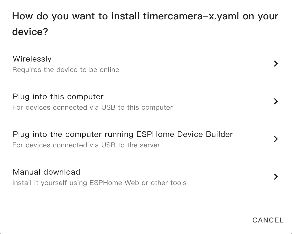
- After modification, click
SAVEandINSTALLin the top right corner, then selectManual Downloadin the pop-up dialog.
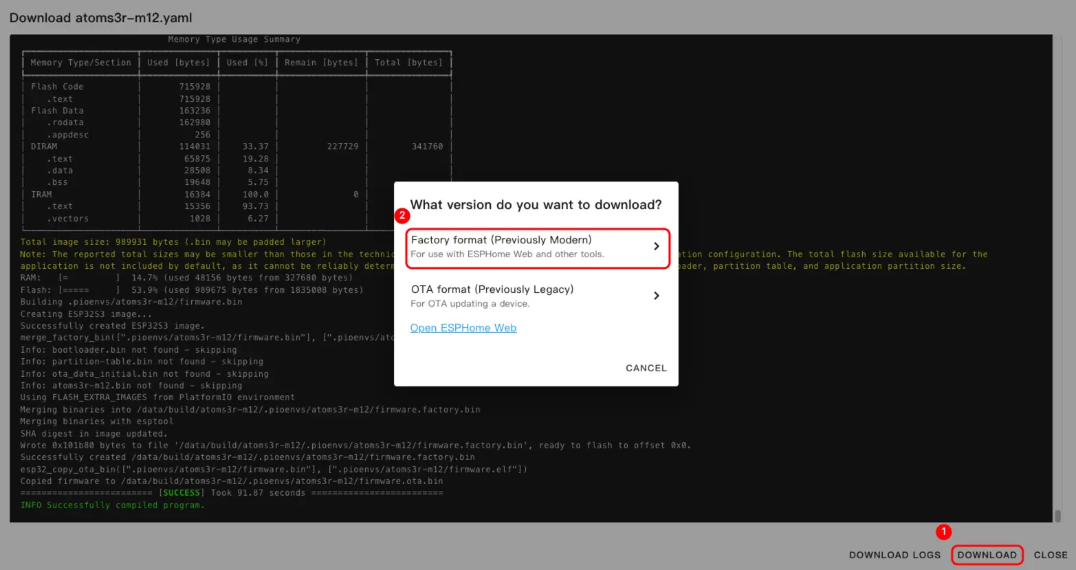
- Once firmware compilation is complete, click
Downloadand select theFactory format(Previously Modern)option to download the firmware.
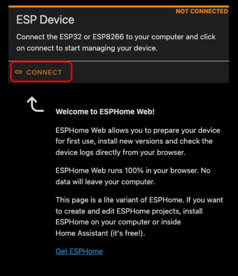
- Connect the device to the host using a USB Type‑C cable. Open ESPHome Web and click
CONNECTto connect the device.
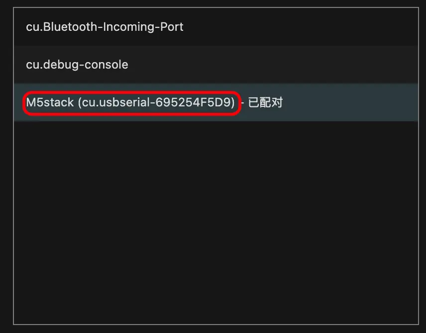
- Find the corresponding serial port number.
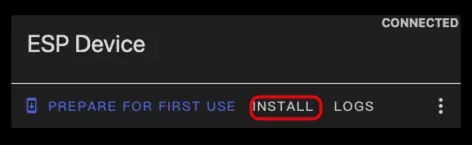
- Click
INSTALL.
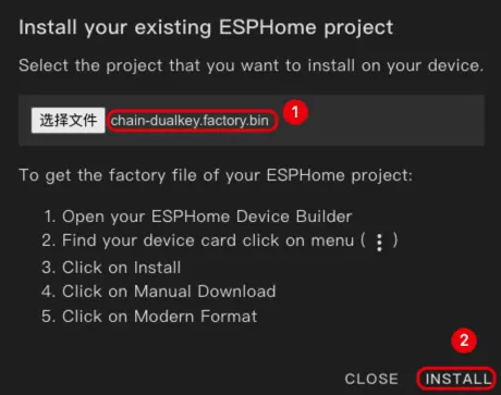
- Select the compiled firmware for uploading.
- After firmware flashing is complete, the device needs to be re-powered to perform a hardware reset.
Quick Start
- In Home Assistant, click
Settings->Device & servicesto view the device.
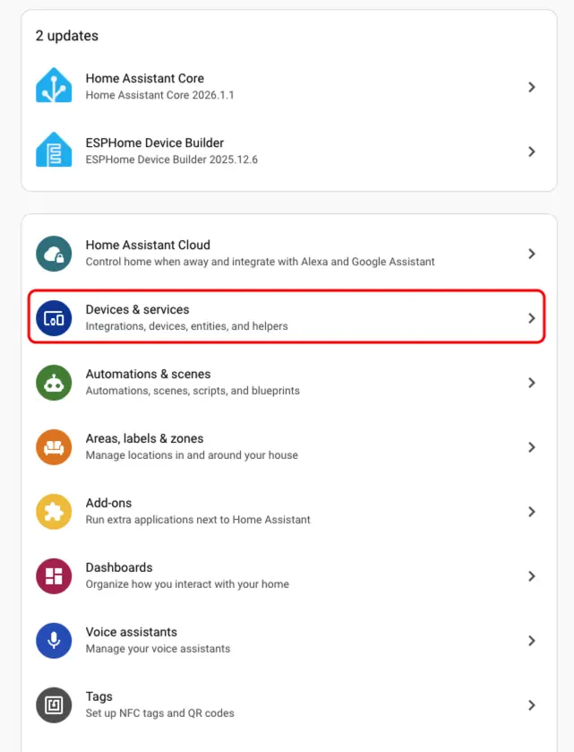
- We can find the corresponding device in the
Discoversection.
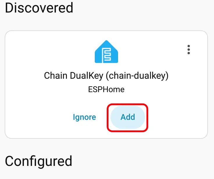
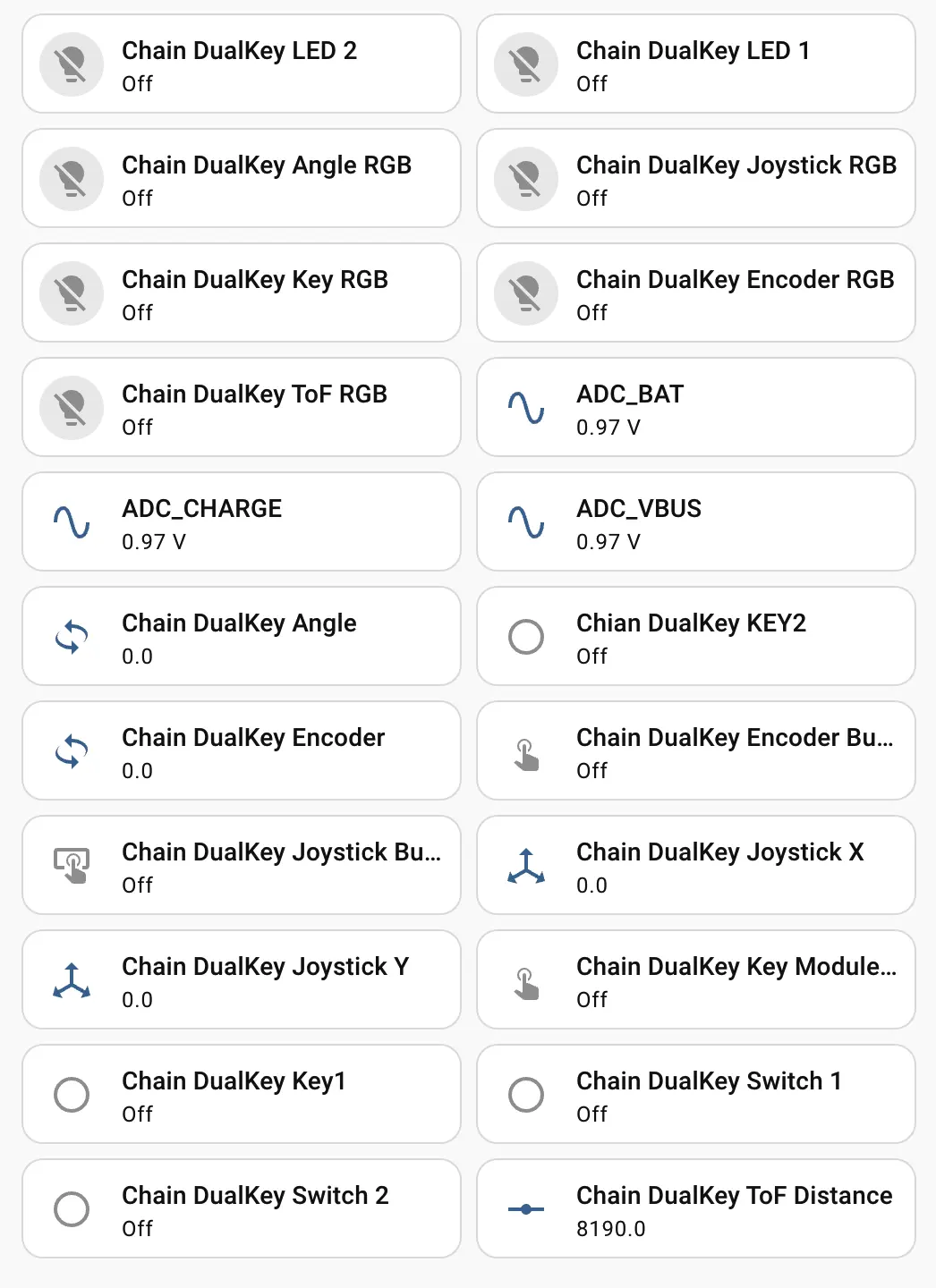
- After adding the device, the data will be displayed correctly.
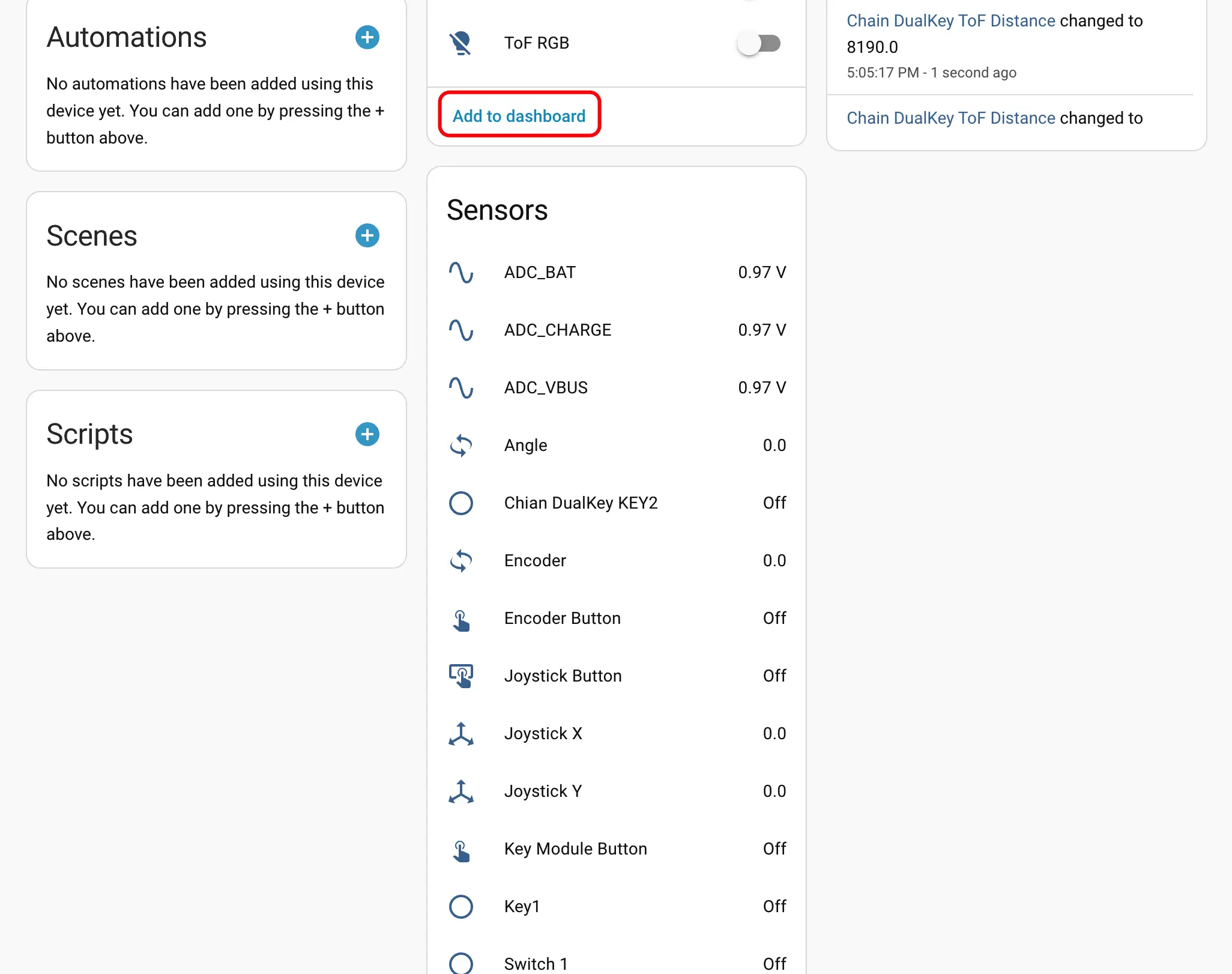
- Finally, add these entities to the Dashboard to obtain the following display effect.