

Home Assistant
Home Assistant
Controller & Devices
Cameras
Components
Lighting
Interfaces and Expansion
Applications
Media Playback
Dashboard
Chain Series ESPHome Component
The Chain Series components provide input functions such as buttons, knobs, joysticks, angle, and distance through the Chain Bus, as well as output and display functions such as buzzers and LED matrices.
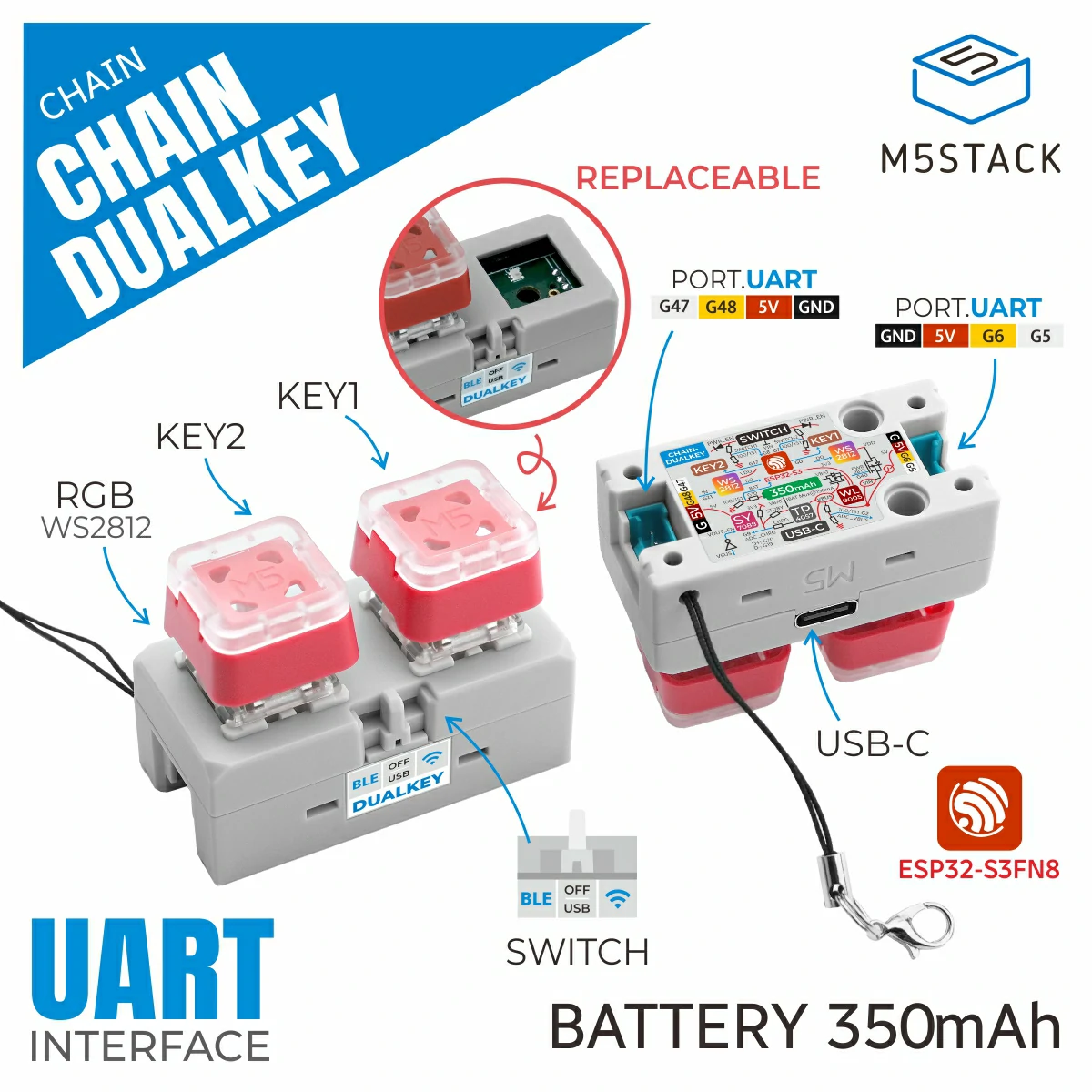
1. Component Overview
| Item | Information |
|---|---|
| Series | Chain Series |
| Expansion modules | Chain Joystick (U205), Chain Key (U206), Chain Encoder (U207), Chain Angle (U208), Chain ToF (U209), Chain Mono (U217), Chain RGB (U218), Chain Buzzer (U224), Chain PIR (U225), Chain MIC (U226), Chain Switch (U227) |
| Main functions | Input functions such as buttons, knobs, joysticks, angle, and distance, as well as output and display functions such as buzzers and LED matrices |
| Communication interface | Chain Bus / UART |
| ESPHome components | m5_chain_* (external components) |
| ESPHome version requirement | / |
2. Component Details
Include External Components
- M5Stack external component - m5_chain_base
- M5Stack external component - m5_chain_joystick
- M5Stack external component - m5_chain_key
- M5Stack external component - m5_chain_encoder
- M5Stack external component - m5_chain_angle
- M5Stack external component - m5_chain_tof
- M5Stack external component - m5_chain_mono
- M5Stack external component - m5_chain_rgb
- M5Stack external component - m5_chain_buzzer
- M5Stack external component - m5_chain_pir
- M5Stack external component - m5_chain_mic
- M5Stack external component - m5_chain_switch
The example below uses the Chain DualKey as the system's main controller. When connecting expansion sensors, set the connection direction and ID numbering order correctly.
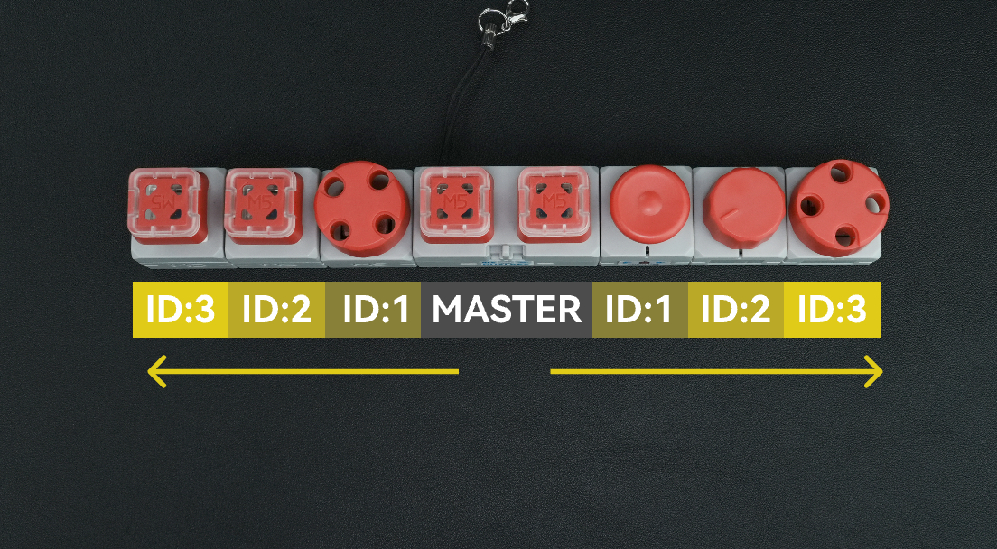
Select the Direction
Using the Chain DualKey as an example, select the corresponding uart_id according to the side of the Chain DualKey to which the expansion sensor is connected:
- Connected to the left side of the Chain DualKey → use
chain_uart_left. - Connected to the right side of the Chain DualKey → use
chain_uart_right.
ID Numbering Rules
chain_index indicates the position of the expansion sensor relative to the Chain DualKey:
- Start numbering from the module closest to the Chain DualKey.
- Increase the ID sequentially (ID:1 → ID:2 → ID:3 …).
- The left and right sides are numbered independently.
- Refer to the diagram above to determine the correct order.
Combined Example
Multiple Chain expansion modules can share the same UART bus. The chain_index of each module increases from the controller outward, and the buses on the left and right sides are numbered independently. For the controller UART pins, Chain Bus power supply, and onboard functions, configure them according to the device page of the controller you use.
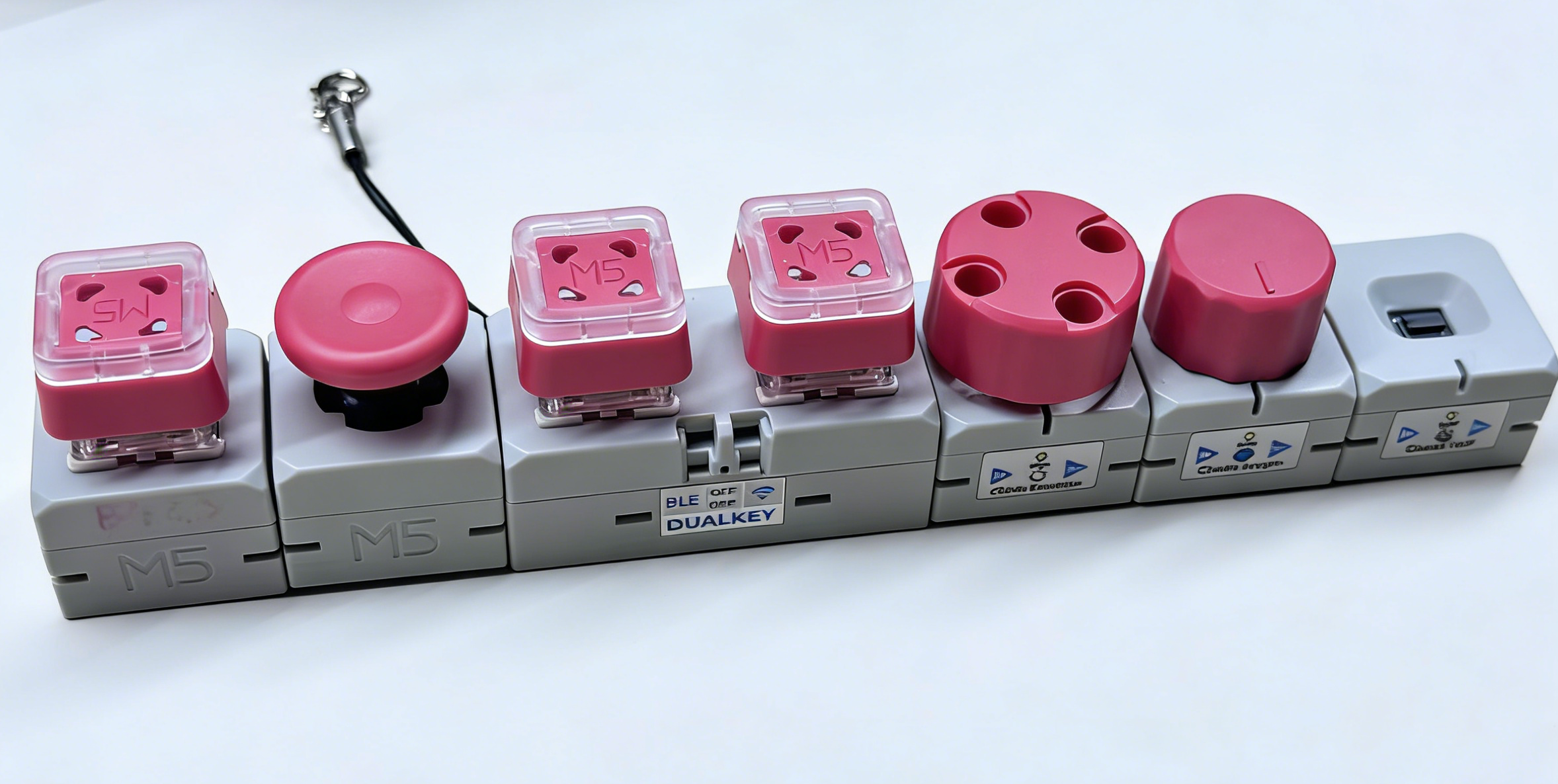
The following example uses the Chain DualKey as the controller: the right side is connected to a Chain Encoder (ID 1), Chain Angle (ID 2), and Chain ToF (ID 3) in sequence, and the left side is connected to a Chain Joystick (ID 1). The configuration consistently uses the latest m5_chain_* components and the chain_index parameter:
uart:
  - id: chain_uart_right
    tx_pin: GPIO6
    rx_pin: GPIO5
    baud_rate: 115200

  - id: chain_uart_left
    tx_pin: GPIO47
    rx_pin: GPIO48
    baud_rate: 115200

external_components:
  - source: github://m5stack/esphome@feat-m5-chain
    components:
      - m5_chain_base
      - m5_chain_encoder
      - m5_chain_angle
      - m5_chain_tof
      - m5_chain_joystick
    refresh: 0s

m5_chain_encoder:
  id: chain_encoder
  uart_id: chain_uart_right
  chain_index: 1

m5_chain_angle:
  id: chain_angle
  uart_id: chain_uart_right
  chain_index: 2

m5_chain_tof:
  id: chain_tof
  uart_id: chain_uart_right
  chain_index: 3

m5_chain_joystick:
  id: chain_joystick
  uart_id: chain_uart_left
chain_index: 1For the sensor, binary sensor, light, and display entity configuration of each module, refer to the corresponding component page: