Home Assistant
Home Assistant
Controller & Devices
Cameras
Components
Lighting
Interfaces and Expansion
Applications
Media Playback
Dashboard
Dial ESPHome Integration
The Dial v1.1 ESPHome integration includes display, touchscreen, rotary encoder, NFC, buzzer, and RTC components.

1. Device Overview
| Item | Information |
|---|---|
| Product Name | Dial v1.1 |
| SKU | K130-V11 |
| Main Functions | Round display, touchscreen, rotary encoder, NFC, buzzer, and RTC |
| Communication | I2C, SPI, GPIO |
| ESPHome Components | mipi_spi, ft5x06, rotary_encoder, binary_sensor.gpio, rc522, rtttl, pcf8563, monochromatic |
| ESPHome Version | / |
2. Component Description
Display and Touchscreen
The round GC9A01A display uses the MIPI SPI Display platform, while touch input uses the FT5x06 Touchscreen platform. The display example only outputs fixed text:
i2c:
  - id: internal_i2c
    sda: GPIO11
    scl: GPIO12
    frequency: 400kHz

spi:
  id: spi_bus
  mosi_pin: GPIO5
  clk_pin: GPIO6

font:
  - file: "gfonts://Roboto"
    id: my_font
    size: 32

display:
  - platform: mipi_spi
    id: round_display
    model: GC9A01A
    cs_pin: GPIO7
    reset_pin: GPIO8
    dc_pin: GPIO4
    invert_colors: true
    data_rate: 40MHz
    update_interval: 1s
    auto_clear_enabled: true
    lambda: |-
      it.print(120, 120, id(my_font), TextAlign::CENTER, "Hello");

touchscreen:
  - platform: ft5x06
    id: touch
    i2c_id: internal_i2c
address: 0x38Backlight
The display backlight uses the Monochromatic Light platform and is controlled through GPIO9:
output:
  - platform: ledc
    pin: GPIO9
    id: backlight_output
    frequency: 1000Hz

light:
  - platform: monochromatic
    name: "Backlight"
    output: backlight_output
    id: display_backlight
default_transition_length: 0sRotary Encoder and Button
The rotary encoder uses the Rotary Encoder Sensor platform, while the button below the display uses the GPIO Binary Sensor platform:
sensor:
  - platform: rotary_encoder
    id: encoder
    name: "Rotary Encoder"
    pin_a:
      number: GPIO40
      mode: INPUT_PULLUP
    pin_b:
      number: GPIO41
      mode: INPUT_PULLUP
    resolution: 4
    min_value: -32768
    max_value: 32767
    publish_initial_value: true

binary_sensor:
  - platform: gpio
    name: Button
    id: front_button
    pin:
      number: GPIO42
      inverted: true
      mode:
        input: true
pullup: trueNFC Reader
The onboard WS1850S uses the RC522 I2C component to detect NFC/RFID tags. The basic event handler only logs the tag UID:
rc522_i2c:
  - id: nfc_reader
    i2c_id: internal_i2c
    address: 0x28
    update_interval: 500ms
    on_tag:
      - lambda: |-
ESP_LOGD("rfid", "Card detected: %s", x.c_str());Buzzer
The onboard buzzer uses the RTTTL component and outputs sound through GPIO3. The example button plays a short alert tone once:
output:
  - platform: ledc
    pin: GPIO3
    id: buzzer
    frequency: 4000Hz

rtttl:
  output: buzzer
  id: rtttl_player
  gain: 0.6

button:
  - platform: template
    name: "The buzzer beeps once"
    id: buzzer_button
    icon: mdi:bell-ring
    on_press:
      - rtttl.play:
          id: rtttl_player
rtttl: "beep:d=4,o=5,b=180:16e,16e"RTC
The onboard RTC uses the PCF8563 Time platform. The RTC is read at startup so that the displayed time is not blank during initialization:
time:
  - platform: pcf8563
    id: rtctime
    i2c_id: internal_i2c
    address: 0x51
update_interval: never3. Reference Example
See dial-example.yaml for the complete example. It includes the main controller, networking, API, display, touchscreen, rotary encoder, NFC, buzzer, RTC, and backlight configuration.
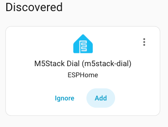
Home Assistant interface when adding the device:
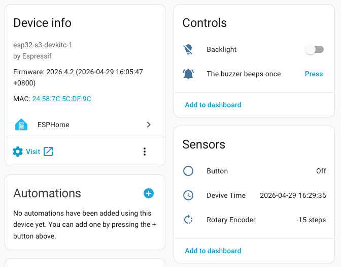
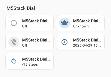
After the device is added, you can view entities such as the rotary encoder, button, NFC, buzzer, backlight, and RTC, and add them to the Dashboard: