

Home Assistant
Home Assistant
Controller & Devices
Cameras
Components
Lighting
Interfaces and Expansion
Applications
Media Playback
Dashboard
Chain DualKey ESPHome Integration
This page introduces the basic components for using the Chain DualKey controller with ESPHome, including Chain Bus, dual-key input, side switches, power control, and key RGB lighting. For driver configurations for Chain expansion modules, see Chain Series ESPHome Components.
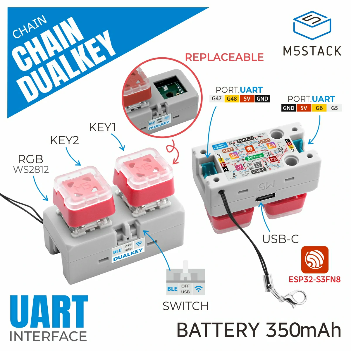
1. Device Overview
| Item | Information |
|---|---|
| Product Name | Chain DualKey |
| SKU | C147 |
| Main Functions | Chain expansion bus controller, dual-key input, and RGB light control |
| Communication | UART, ADC, GPIO |
| ESPHome Components | uart, adc, binary_sensor.gpio, output.gpio, light.esp32_rmt_led_strip, light.partition |
| ESPHome Version | / |
2. Component Description
Chain Bus
The Chain interfaces on the left and right sides each use an independent UART. The uart_id of an expansion module must match its actual connection direction. The chain_id starts at the module closest to the DualKey and increases sequentially.
uart:
  - id: chain_uart_right
    tx_pin: GPIO6
    rx_pin: GPIO5
    baud_rate: 115200

  - id: chain_uart_left
    tx_pin: GPIO48
    rx_pin: GPIO47
baud_rate: 115200Keys and Side Switches
The two mechanical keys use GPIO binary sensors. GPIO0 and GPIO17 are active low. The side switches use GPIO7 and GPIO8.
binary_sensor:
  - platform: gpio
    name: "KEY 1"
    pin:
      number: GPIO0
      inverted: true
      mode: INPUT_PULLUP

  - platform: gpio
    name: "KEY 2"
    pin:
      number: GPIO17
      inverted: true
      mode: INPUT_PULLUP

  - platform: gpio
    name: "SWITCH 1"
    pin: GPIO7

  - platform: gpio
    name: "SWITCH 2"
pin: GPIO8RGB LED Power
GPIO40 controls the power supply for the two key RGB LEDs. Keep this pin high when using the light component:
switch:
  - platform: gpio
    id: key_light_power
    pin: GPIO40
    internal: true
restore_mode: ALWAYS_ONKey RGB LEDs
The two DualKey key LEDs are connected to GPIO21. Use partition to split the LED strip into two independent Light entities.
light:
  - platform: esp32_rmt_led_strip
    id: key_light_raw
    internal: true
    pin: GPIO21
    num_leds: 2
    chipset: WS2812
    rgb_order: GRB
    restore_mode: ALWAYS_OFF

  - platform: partition
    name: "Key Light 1"
    id: key_light_1
    segments:
      - id: key_light_raw
        from: 0
        to: 0

  - platform: partition
    name: "Key Light 2"
    id: key_light_2
    segments:
      - id: key_light_raw
        from: 1
to: 1Battery and Bus Status
The DualKey battery, VBUS, and charging status can be read using the ADC component. Configure the ADC pins and attenuation parameters according to the hardware version.
sensor:
  - platform: adc
    pin: GPIO10
    name: "ADC Battery"
    update_interval: 1s
  - platform: adc
    pin: GPIO2
    name: "ADC VBUS"
    update_interval: 1s
  - platform: adc
    pin: GPIO9
    name: "ADC Charge"
    update_interval: 1s