

Home Assistant
Home Assistant
Controller & Devices
Cameras
Components
Lighting
Interfaces and Expansion
Applications
Media Playback
Dashboard
Unit EXT.IO2 / Stamp IO ESPHome Component
The Unit EXT.IO2 / Stamp IO component expands GPIO, ADC, PWM, and other input/output functions over I2C.
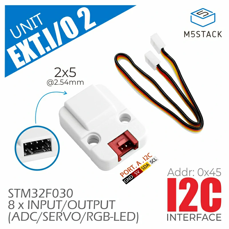
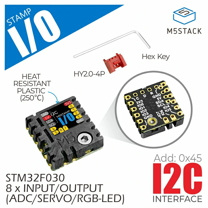
1. Component Overview
| Item | Information |
|---|---|
| Product Name | Unit EXT.IO2 / Stamp IO |
| SKU | U011-B / S002 |
| Main Function | GPIO, ADC, and PWM expansion |
| Communication Interface | I2C |
| Default I2C Address | 0x45 |
| ESPHome Component | extio2 (external component) |
| ESPHome Version | / |
2. Component Details
External Component Integration
Add the External Components configuration to the YAML file to load the EXT.IO2 / Stamp IO component.
external_components:
  - source: github://m5stack/esphome-yaml/components
    components: [extio2]
refresh: 0sHub Component
Add the Hub component before using any EXT.IO2 functions:
extio2:
id: extio2_hubConfigurable Options
- id (optional, ID): specifies an ID for the Hub component.
- address (optional, int): I2C address; default
0x45. - reset (optional, boolean): performs a software reset, sets all pins to output mode and low level; default
true. - pwm_freq (optional, enum): global PWM frequency for all channels; default
1kHz.2kHz1kHz500Hz250Hz125Hz
- Other options supported by I2C devices.
GPIO Pins
EXT.IO2 pins can be used wherever ESPHome accepts a standard GPIO pin reference, for example in switch and binary_sensor components.
# Digital output - switch
switch:
- platform: gpio
name: "EXT.IO2 GPIO 0"
pin:
extio2_id: extio2_hub
number: 0
mode:
output: true
# Digital input - binary sensor
binary_sensor:
- platform: gpio
name: "EXT.IO2 GPIO 1"
pin:
extio2_id: extio2_hub
number: 1Pin Configuration
- extio2_id (required, ID): the ID of the EXT.IO2 bus controller.
- number (required, int): pin number, range
0-7. - inverted (optional, boolean): inverts the pin logic; default
false. - mode (required): selects
inputoroutput, with optionalpullup,pulldown, oropen_drainflags.
Sensors (ADC)
The sensor platform reads analog values from eight ADC-capable pins.
sensor:
- platform: extio2
extio2_id: extio2_hub
name: "ADC Sensors 0"
channel: ADC_0
resolution: 12BIT
update_interval: 5sConfiguration
- extio2_id (optional, ID): the ID of the EXT.IO2 bus controller.
- channel (required, enum): ADC channel to read, from
ADC_0toADC_7. - resolution (optional, enum): ADC resolution; default
8BIT.8BIT: 8-bit resolution, range 0-255.12BIT: 12-bit resolution, range 0-4095.
- update_interval (optional, time): polling interval; default
60s. - For other options, see Sensors.
Output (PWM)
The output platform drives any pin as a PWM output. The duty cycle is represented as a floating-point value from 0.0 to 1.0, internally mapped to 0-100%.
output:
- platform: extio2
extio2_id: extio2_hub
id: pwm_ch0
channel: PWM_0
light:
- platform: monochromatic
name: "PWM Light 0"
output: pwm_ch0
effects:
- pulse:Configuration
- extio2_id (optional, ID): the ID of the EXT.IO2 bus controller.
- id (required, ID): the ID of this output.
- channel (required, enum): PWM channel to use, from
PWM_0toPWM_7. - For other options, see Float Output.
pwm_freq; all PWM channels share the same frequency.Number (Servo)
The number platform controls servos in two modes: angle (degrees) and pulse width (microseconds).
Angle Mode
Controls the servo position by angle (0-180 degrees).
number:
- platform: extio2
extio2_id: extio2_hub
name: "Servo 0"
type: angle
channel: SERVO_0
min_value: 0
max_value: 180
step: 3Pulse-Width Mode
Controls the servo using the raw pulse width (microseconds).
number:
- platform: extio2
extio2_id: extio2_hub
name: "Servo 1"
type: pulse
channel: SERVO_1
min_value: 500
max_value: 2500
step: 100Configuration
- extio2_id (optional, ID): the ID of the EXT.IO2 bus controller.
- type (required, enum): servo control mode.
angle: angle control.pulse: pulse-width control.
- channel (required, enum): servo channel to use, from
SERVO_0toSERVO_7. - min_value (optional, float): minimum value; default
0.0in angle mode and500.0in pulse mode. - max_value (optional, float): maximum value; default
180.0in angle mode and2500.0in pulse mode. - step (optional, float): step value; default
3.0in angle mode and100.0in pulse mode. - For other options, see Number.
| Mode | Unit | Minimum | Maximum | Step |
|---|---|---|---|---|
angle | ° | 0 | 180 | 3 |
pulse | us | 500 | 2500 | 100 |
Lights
The light platform supports two modes: a single RGB LED on a specified pin, or an addressable LED strip using consecutive pins starting at pin 0.
Single RGB LED
Controls a single RGB LED on the specified pin.
light:
- platform: extio2
extio2_id: extio2_hub
name: "EXT.IO2 Light 2"
type: light
channel: LIGHT_2Addressable LED Strip
Controls consecutive RGB LEDs starting at pin 0 and supports all ESPHome addressable-light effects.
light:
- platform: extio2
extio2_id: extio2_hub
name: "LED Strip"
type: addressable_light
num_leds: 8Configuration
- extio2_id (optional, ID): the ID of the EXT.IO2 bus controller.
- type (required, enum): light mode.
light: single RGB LED.addressable_light: addressable LED strip.
- channel (required for
light, enum): pin to use, fromLIGHT_0toLIGHT_7. - num_leds (required for
addressable_light, int): number of LEDs, range1-8, assigned consecutively starting at pin 0. - For other options, see Light.
num_leds: 3 uses pins 0, 1, and 2. The hardware has no brightness-control register; brightness is implemented by scaling the RGB values in software.3. Example
This example demonstrates the GPIO input/output, ADC, PWM, servo, and RGB light platforms. Adjust the controller I2C pins to match the actual wiring.
i2c:
sda: GPIO2
scl: GPIO1
extio2:
  id: extio2_hub
address: 0x45
reset: true
pwm_freq: 1kHz
# GPIO - digital output
switch:
- platform: gpio
name: "EXT.IO2 GPIO 0"
pin:
extio2_id: extio2_hub
number: 0
mode:
output: true
# GPIO - digital input
binary_sensor:
- platform: gpio
name: "EXT.IO2 GPIO 1"
pin:
extio2_id: extio2_hub
number: 1
mode:
input: true
pullup: true
# ADC sensor
sensor:
- platform: extio2
extio2_id: extio2_hub
name: "ADC Sensors 2"
channel: ADC_2
resolution: 12BIT
update_interval: 5s
# PWM output used as a monochromatic light
output:
- platform: extio2
extio2_id: extio2_hub
id: pwm_ch3
channel: PWM_3
light:
- platform: monochromatic
name: "PWM Light 3"
output: pwm_ch3
effects:
- pulse:
# Single RGB LED
- platform: extio2
extio2_id: extio2_hub
name: "RGB Light 6"
type: light
channel: LIGHT_6
# Addressable LED strip (all 8 pins)
- platform: extio2
extio2_id: extio2_hub
name: "LED Strip"
type: addressable_light
num_leds: 8
number:
# Servo - angle control
- platform: extio2
extio2_id: extio2_hub
name: "Servo 4"
type: angle
channel: SERVO_4
# Servo - pulse-width control
- platform: extio2
extio2_id: extio2_hub
name: "Servo 5"
type: pulse
channel: SERVO_5