Home Assistant
Home Assistant
Controller & Devices
Cameras
Components
Lighting
Interfaces and Expansion
Applications
Media Playback
Dashboard
StamPLC ESPHome Integration
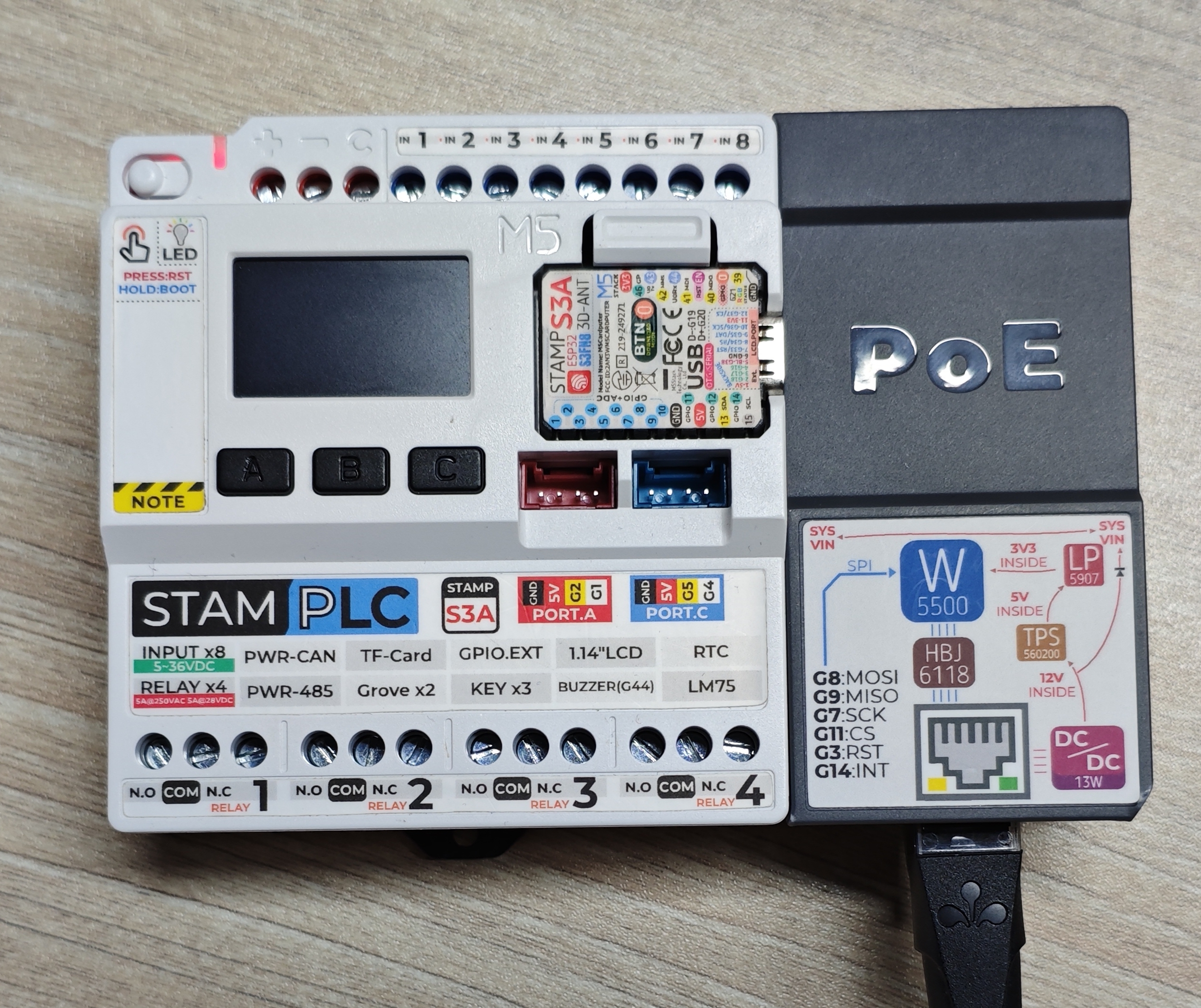
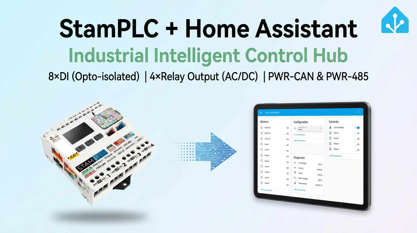
The StamPLC ESPHome integration includes input, relay, measurement, display, and Ethernet components for the main unit and AC/PoE expansions.
1. Device Overview
| Item | Information |
|---|---|
| Product Name | StamPLC |
| SKU | K141 |
| Main Functions | Digital I/O, relays, analog measurement, display, RTC, and Ethernet expansion |
| Communication | I2C, SPI, GPIO, Ethernet |
| ESPHome Components | aw9523 (external component), pi4ioe5v6408, ina226, lm75b, rx8130, mipi_spi, rtttl, ethernet |
| ESPHome Version | 2025.8.0 or later |
2. Component Description
AW9523 External Component
StamPLC uses the aw9523 external component from the community repository to drive digital inputs and relays:
external_components:
  - source: github://Beormund/esphome-m5stamplc
components: [aw9523]IO Expander Initialization
GPIO3 must remain high before the two IO expanders are initialized. Do not change the declaration order of power_supply, PI4IOE5V6408, and aw9523:
power_supply:
  id: pin3_output_high
  pin:
    number: GPIO3
    ignore_strapping_warning: true
  enable_on_boot: true

pi4ioe5v6408:
  - id: pi4ioe5v6408_1
    address: 0x43

aw9523:
  - id: aw9523_1
address: 0x59Digital Inputs and Relays
AW9523 provides eight digital inputs and four relay outputs. The following example shows the minimum configuration for one channel of each type. To configure the remaining channels, change the expander pin number:
binary_sensor:
  - platform: gpio
    name: "Input 1"
    pin:
      aw9523: aw9523_1
      number: 4
      mode:
        input: true

switch:
  - platform: gpio
    name: "Relay 1"
    restore_mode: RESTORE_DEFAULT_OFF
    pin:
      aw9523: aw9523_1
      number: 0
      mode:
output: trueElectrical and Temperature Measurement
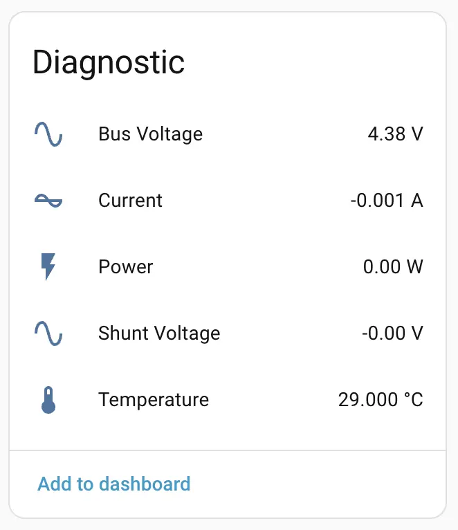
Use the official INA226 platform for input voltage, current, and power measurements, and the LM75B platform for onboard temperature:
sensor:
  - platform: ina226
    shunt_resistance: 0.01
    max_current: 8.192
    current:
      name: "Current"
    power:
      name: "Power"
    bus_voltage:
      name: "Bus Voltage"

  - platform: lm75b
    name: "Temperature"
update_interval: 60sLCD and Buzzer
The LCD uses the official MIPI SPI Display platform. The minimum configuration below uses a test pattern to verify that the display driver is working. The buzzer uses LEDC Output and RTTTL:
display:
  platform: mipi_spi
  model: ST7789V
  dimensions:
    width: 240
    height: 240
    offset_width: 42
    offset_height: 55
  dc_pin: GPIO6
  cs_pin: GPIO12
  invert_colors: true
  show_test_card: true

output:
  - platform: ledc
    pin: GPIO44
    id: buzzer

rtttl:
output: buzzerStamPLC AC Expansion
The StamPLC AC expansion uses a second PI4IOE5V6408 expander to control the AC relay and three-color indicator LEDs. The following example retains the basic GPIO configuration for one relay and three LEDs:
pi4ioe5v6408:
  - id: pi4ioe5v6408_1
    address: 0x43
  - id: pi4ioe5v6408_2
    address: 0x44

switch:
  - platform: gpio
    name: "StamPLC AC Relay"
    restore_mode: RESTORE_DEFAULT_OFF
    pin:
      pi4ioe5v6408: pi4ioe5v6408_2
      number: 2
      mode:
        output: true

  - platform: gpio
    name: "StamPLC AC LED Red"
    restore_mode: ALWAYS_OFF
    pin:
      pi4ioe5v6408: pi4ioe5v6408_2
      number: 5
      inverted: true
      mode:
        output: true

  - platform: gpio
    name: "StamPLC AC LED Green"
    restore_mode: ALWAYS_OFF
    pin:
      pi4ioe5v6408: pi4ioe5v6408_2
      number: 6
      inverted: true
      mode:
        output: true

  - platform: gpio
    name: "StamPLC AC LED Blue"
    restore_mode: ALWAYS_OFF
    pin:
      pi4ioe5v6408: pi4ioe5v6408_2
      number: 7
      inverted: true
      mode:
output: trueStamPLC PoE Expansion
StamPLC PoE uses the official Ethernet component to drive the W5500:
ethernet:
  id: ethernet_1
  type: W5500
  clk_pin: GPIO7
  mosi_pin: GPIO8
  miso_pin: GPIO9
  cs_pin: GPIO11
clock_speed: 20MHzwifi; the two network components cannot be configured at the same time.RTC
The onboard RTC uses the RX8130 platform. The RTC is read at startup and written back after SNTP synchronization:
time:
  - platform: rx8130
    id: rx8130_time
    update_interval: 30min
  - platform: sntp
    id: sntp_time
    timezone: Europe/London
    on_time_sync:
      then:
        - rx8130.write_time:
id: rx8130_time3. Reference Examples
Complete configuration and expansion references:
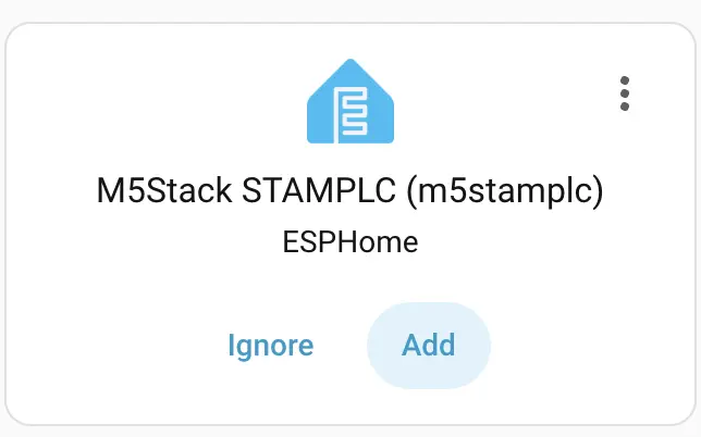
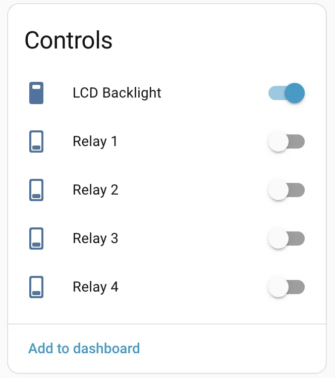
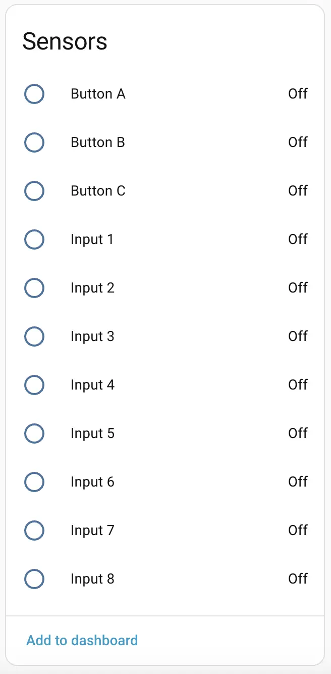
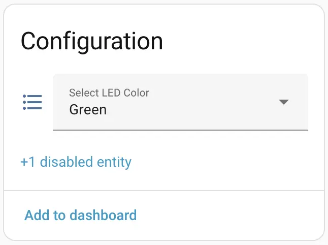
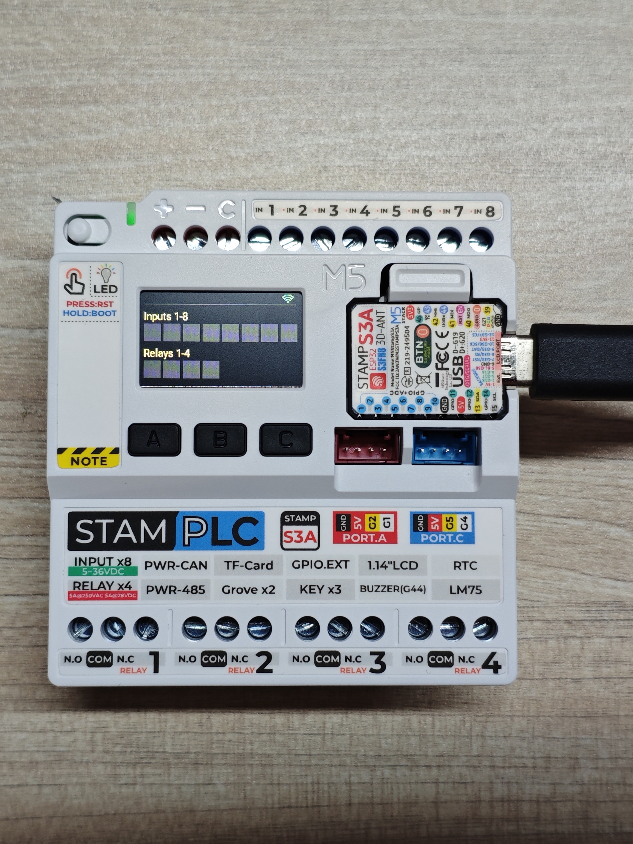
After connecting the device to Home Assistant, you can view input, relay, measurement, and control entities:
Operating examples for StamPLC AC and StamPLC PoE: