Home Assistant
Home Assistant
Controller & Devices
Cameras
Components
Lighting
Interfaces and Expansion
Applications
Media Playback
Dashboard
StackChan ESPHome Integration
The StackChan ESPHome integration includes power, display, audio, camera, sensor, servo, and lighting components.
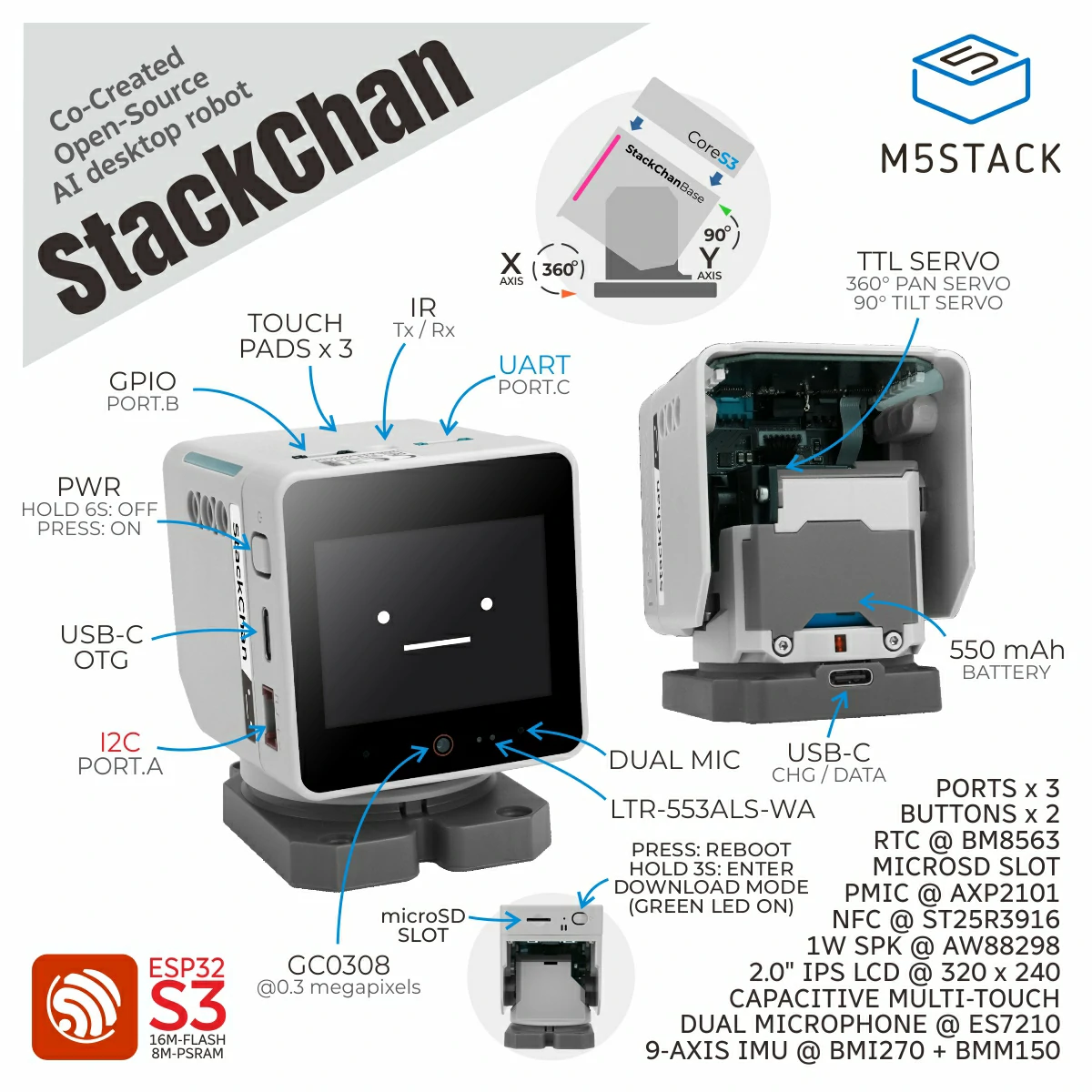
1. Device Overview
| Item | Information |
|---|---|
| Product Name | StackChan |
| SKU | K151 / K151-R |
| Main Functions | Display, audio, camera, sensors, servo, and lighting control |
| Communication | I2C, I2S, UART, SPI, GPIO |
| ESPHome Components | axp2101, aw9523b, aw88298, si12t, m5ioe1, ftservo, scs9009 (external components), plus es7210, i2s_audio, mipi_spi, ft63x6, esp32_camera, ltr_als_ps, ina226, remote_transmitter, remote_receiver, bm8563 |
| ESPHome Version | / |
2. Component Description
External Components
StackChan uses M5Stack external components for power, the audio amplifier, IO expansion, head touch, the light bar, and servos:
external_components:
  - source: github://m5stack/esphome-yaml/components
    components: [axp2101, aw88298, aw9523b, si12t, m5ioe1, ftservo, scs9009]
refresh: 0sPower Management and IO Expansion
axp2101 drives the CoreS3 power rails and LCD backlight, aw9523b controls reset and power direction, and m5ioe1 provides expansion IO for the servos and light bar:
i2c:
  - id: bsp_bus
    sda: GPIO12
    scl: GPIO11
    frequency: 100kHz

axp2101:
  id: axp2101_pmu
  i2c_id: bsp_bus

aw9523b:
  id: aw9523b_hub
  i2c_id: bsp_bus
  p0_drive_mode: PUSH_PULL

m5ioe1:
  id: m5ioe1_hub
  i2c_id: bsp_bus
  reset: true

output:
  - platform: axp2101
    type: range
    channel: DLDO1
    id: lcd_backlight_output
    min_voltage: 2600
max_voltage: 3300The BUS output and USB OTG require the boost circuit to be enabled first:
switch:
  - platform: gpio
    name: "BOOST_EN"
    pin:
      aw9523b_id: aw9523b_hub
      number: 15
    restore_mode: RESTORE_DEFAULT_ON

  - platform: gpio
    name: "USB_OTG_EN"
    pin:
      aw9523b_id: aw9523b_hub
      number: 5
    restore_mode: RESTORE_DEFAULT_OFF

  - platform: gpio
    name: "BUS_OUT_EN"
    pin:
      aw9523b_id: aw9523b_hub
      number: 1
restore_mode: RESTORE_DEFAULT_ONBUS_OUT_EN and USB_OTG_EN take effect only after BOOST_EN is enabled. Confirm the power direction of peripheral devices before changing the default states.Microphone and Speaker
The microphone uses the official ES7210 Audio ADC and I2S Microphone. The speaker uses the aw88298 external Audio DAC and I2S Speaker:
i2s_audio:
  id: i2s_audio_bus
  i2s_lrclk_pin: GPIO33
  i2s_bclk_pin: GPIO34
  i2s_mclk_pin:
    number: GPIO0
    ignore_strapping_warning: true

audio_adc:
  - platform: es7210
    id: es7210_adc
    i2c_id: bsp_bus
    bits_per_sample: 16bit
    sample_rate: 16000
    mic_gain: 36

microphone:
  - platform: i2s_audio
    id: i2s_mic
    i2s_din_pin: GPIO14
    adc_type: external
    sample_rate: 16000
    bits_per_sample: 16bit
    i2s_audio_id: i2s_audio_bus

audio_dac:
  - platform: aw88298
    id: aw88298_dac
    i2c_id: bsp_bus
    sample_rate: 48000

speaker:
  - platform: i2s_audio
    id: i2s_speaker
    i2s_audio_id: i2s_audio_bus
    dac_type: external
    i2s_dout_pin: GPIO13
audio_dac: aw88298_dacLCD and Touchscreen
The LCD uses the official MIPI SPI Display platform, while the touchscreen uses the FT63X6 platform. The minimum display configuration enables a test pattern:
spi:
  - id: spi_bus
    clk_pin: GPIO36
    mosi_pin: GPIO37

display:
  - platform: mipi_spi
    model: M5CORE
    dc_pin: GPIO35
    reset_pin:
      aw9523b_id: aw9523b_hub
      number: 9
    cs_pin:
      number: GPIO3
      ignore_strapping_warning: true
    data_rate: 40MHz
    invert_colors: true
    show_test_card: true

touchscreen:
  - platform: ft63x6
    i2c_id: bsp_bus
    reset_pin:
      aw9523b_id: aw9523b_hub
number: 0Camera
The GC0308 uses the official ESP32 Camera component. setup_priority: -200 ensures that power and the IO expanders are initialized first:
esp32_camera:
  name: "Camera"
  i2c_id: bsp_bus
  setup_priority: -200
  vsync_pin:
    number: GPIO46
    ignore_strapping_warning: true
  href_pin: GPIO38
  external_clock:
    pin: GPIO2
    frequency: 20MHz
  pixel_clock_pin:
    number: GPIO45
    ignore_strapping_warning: true
  data_pins: [GPIO39, GPIO40, GPIO41, GPIO42, GPIO15, GPIO16, GPIO48, GPIO47]
  resolution: 320x240
frame_buffer_location: PSRAMsetup_priority: -200, or the camera may initialize before the power and reset signals are stable.Ambient Light, Proximity, and Power Measurement
LTR-553ALS-WA uses the official LTR-ALS-PS platform. Voltage, current, and power use the official INA226 platform:
sensor:
  - platform: ltr_als_ps
    address: 0x23
    i2c_id: bsp_bus
    type: ALS_PS
    ambient_light:
      name: "Ambient Light"
    ps_counts: "Proximity Counts"

  - platform: ina226
    i2c_id: bsp_bus
    address: 0x41
    shunt_resistance: 0.01 ohm
    max_current: 3.2A
    current:
      name: "INA226 Current"
    power:
      name: "INA226 Power"
    bus_voltage:
name: "INA226 Bus Voltage"Servos
The two SCS9009 servos use addresses 1 and 2 respectively. The ftservo Number platform provides basic angle control:
uart:
  tx_pin: GPIO6
  rx_pin: GPIO7
  baud_rate: 1000000

scs9009:

ftservo:
  - platform: scs9009
    address: 1
    id: x_servo
  - platform: scs9009
    address: 2
    id: y_servo

number:
  - platform: ftservo
    ftservo_id: x_servo
    angle:
      name: "Servo X Angle"
      min_value: -164
      max_value: 164
      use_raw_angle: false
      angle_offset: 164
step: 5Head Touch
The si12t external component provides three capacitive touch states. The following example shows the first channel:
si12t:
  id: touch_hub
  i2c_id: bsp_bus

text_sensor:
  - platform: si12t
    name: "Touch Sensor 1"
    channel: CH_1
update_interval: 1sRGB Light Bar
The 12 RGB LEDs use the m5ioe1 Light platform. M5IOE1 pin 14 must remain enabled, and the BUS side also requires BOOST_EN and BUS_OUT_EN to provide 5 V:
switch:
  - platform: gpio
    name: "M5IOE1 Pin 14"
    pin:
      m5ioe1_id: m5ioe1_hub
      number: 13
      mode:
        output: true
        pullup: true
    restore_mode: RESTORE_DEFAULT_ON

light:
  - platform: m5ioe1
    name: "StackChan Light Bar"
num_led: 12Infrared Transceiver
The onboard infrared transmitter and receiver use the official ESPHome Remote Transmitter and Remote Receiver components:
remote_transmitter:
  pin: GPIO5
  carrier_duty_percent: 50%
  non_blocking: true

remote_receiver:
pin: GPIO10RTC
The onboard RTC uses the official BM8563 platform. The RTC is read at startup and written back after Home Assistant synchronizes the time:
time:
  - platform: bm8563
    i2c_id: bsp_bus
    update_interval: never
  - platform: homeassistant
    on_time_sync:
      then:
- bm8563.write_time:3. Reference Example
Import the complete configuration through packages:
packages:
  remote_package_files:
    url: https://github.com/m5stack/esphome-yaml
    files: [examples/kit/stackchan-bsp.factory.yaml]
    ref: main
refresh: 0sSee stackchan-bsp.factory.yaml for the complete source.
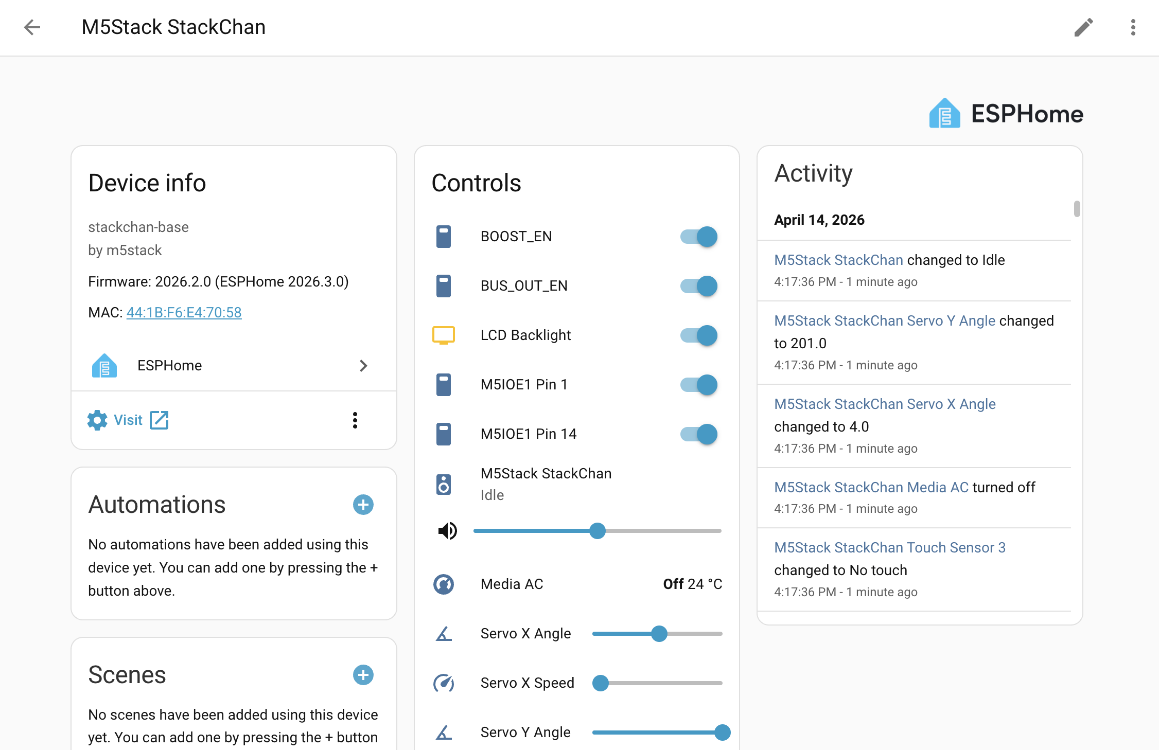
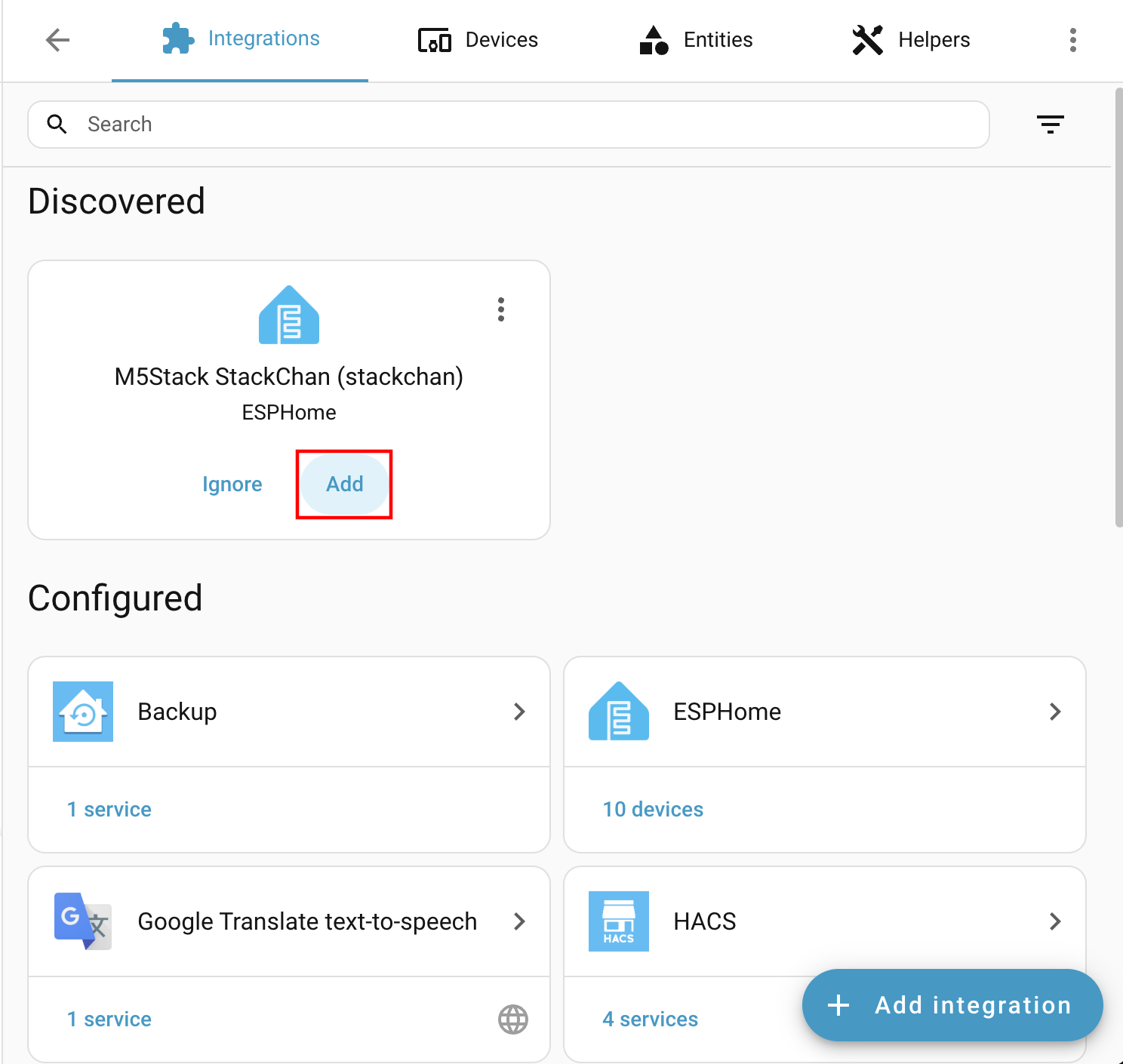
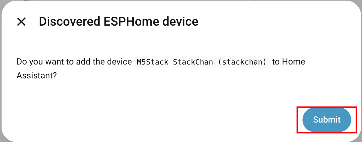
After connecting the device to Home Assistant, you can view the basic StackChan entities:
Device entities in the ESPHome integration: