

Home Assistant
Home Assistant
Controller & Devices
Cameras
Components
Lighting
Interfaces and Expansion
Applications
Media Playback
Dashboard
PowerHub ESPHome Integration
The PowerHub ESPHome integration includes power channels, measurement, interface control, and RTC components.

1. Device Overview
| Item | Information |
|---|---|
| Product Name | PowerHub |
| SKU | C148 / K148 |
| Main Functions | Multi-channel power output, power measurement, interface control, and RTC |
| Communication | I2C, UART, CAN, RS485, GPIO |
| ESPHome Components | powerhub (external component) |
| ESPHome Version | / |
2. Component Description
PowerHub External Component
PowerHub communicates with the onboard STM32 coprocessor through the M5Stack powerhub external component:
external_components:
  - source: github://m5stack/esphome-yaml/components@main
    components: [powerhub]
    refresh: 0s

powerhub:Buttons and Status
The binary_sensor platform provides the top PMU button, while the text_sensor platform provides the charging status and external input power status:
binary_sensor:
  - platform: powerhub
    button:
      name: "Top PMU Button"

text_sensor:
  - platform: powerhub
    charge_status:
      name: "Battery Charge Status"
    vin_status:
name: "External Input Power Status"Voltage, Current, and Battery Level
The sensor platform reads the voltage and current of the battery and each output channel. The following example shows the basic entities for the battery and Port.A. Port.C, CAN, RS485, and USB use the same configuration pattern:
sensor:
  - platform: powerhub
    battery_voltage:
      name: "Battery Voltage"
    battery_current:
      name: "Battery Current"
    battery_level:
      name: "Battery Percentage"
    grove_red_voltage:
      name: "Port.A Voltage"
    grove_red_current:
name: "Port.A Current"VAMeter Power and the corresponding channel power switch, and connect an actual load. Readings without power or a load are not meaningful.Power Channels
The switch platform controls the power channels for USB, Port.A, Port.C, RS485/CAN, charging, and the measurement circuit:
switch:
  - platform: powerhub
    channel: USB
    name: "USB Power"

  - platform: powerhub
    channel: GROVE_RED
    name: "Port.A Power"

  - platform: powerhub
    channel: VAMETER
    name: "VAMeter Power"
restore_mode: RESTORE_DEFAULT_ONInterface Parameters
Use the select platform to set the USB operating mode and the number platform to set the RS485/CAN output voltage and current limits:
select:
  - platform: powerhub
    usb_mode:
      name: "USB Mode"

number:
  - platform: powerhub
    rs485_can_output_voltage:
      name: "RS485&CAN Output Voltage"
      mode: box
    rs485_can_current_limit:
      name: "RS485&CAN Output Current Limit"
mode: boxRS485&CAN Power channel must also be enabled for the output to work.Indicators
The light platform independently controls the USB, Port.A, Port.C, RS485/CAN, charging, and power status indicators. The following example shows the USB-A status indicator:
light:
  - platform: powerhub
    channel: USB_A
name: "USB A Light"RTC
The onboard RTC is provided through the powerhub Time platform. It is read at startup and written back after Home Assistant synchronizes the time:
time:
  - platform: powerhub
    id: powerhub_time
    update_interval: never
  - platform: homeassistant
    on_time_sync:
      then:
- powerhub.write_time:3. Reference Example
See the complete device configuration in powerhub.factory.yaml. It includes networking, provisioning, API, all entities, and indicator automation.
After connecting the device to Home Assistant, you can view entities such as power channels, measurements, and interface parameters:
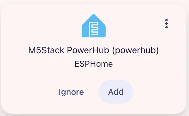
Home Assistant Dashboard example:
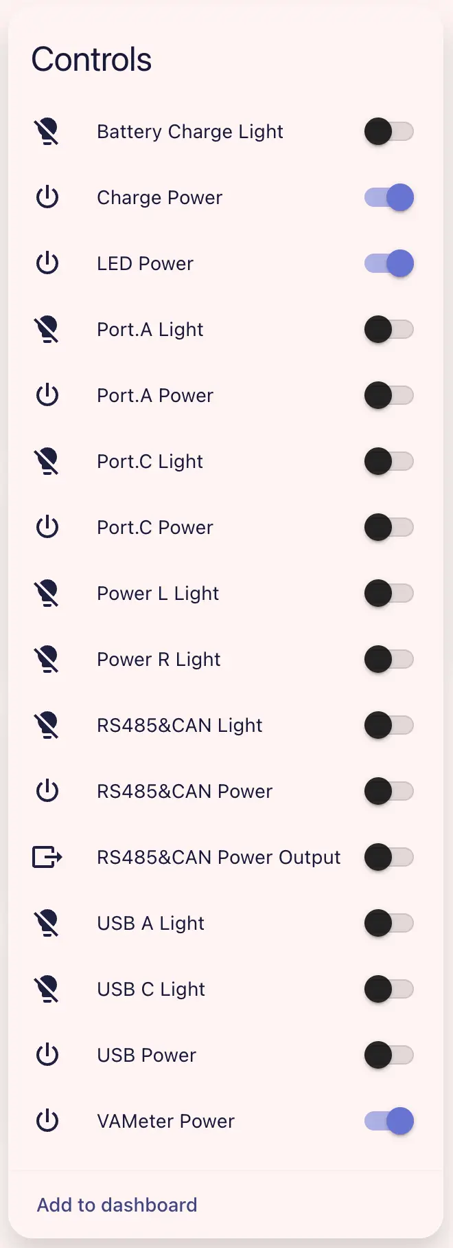
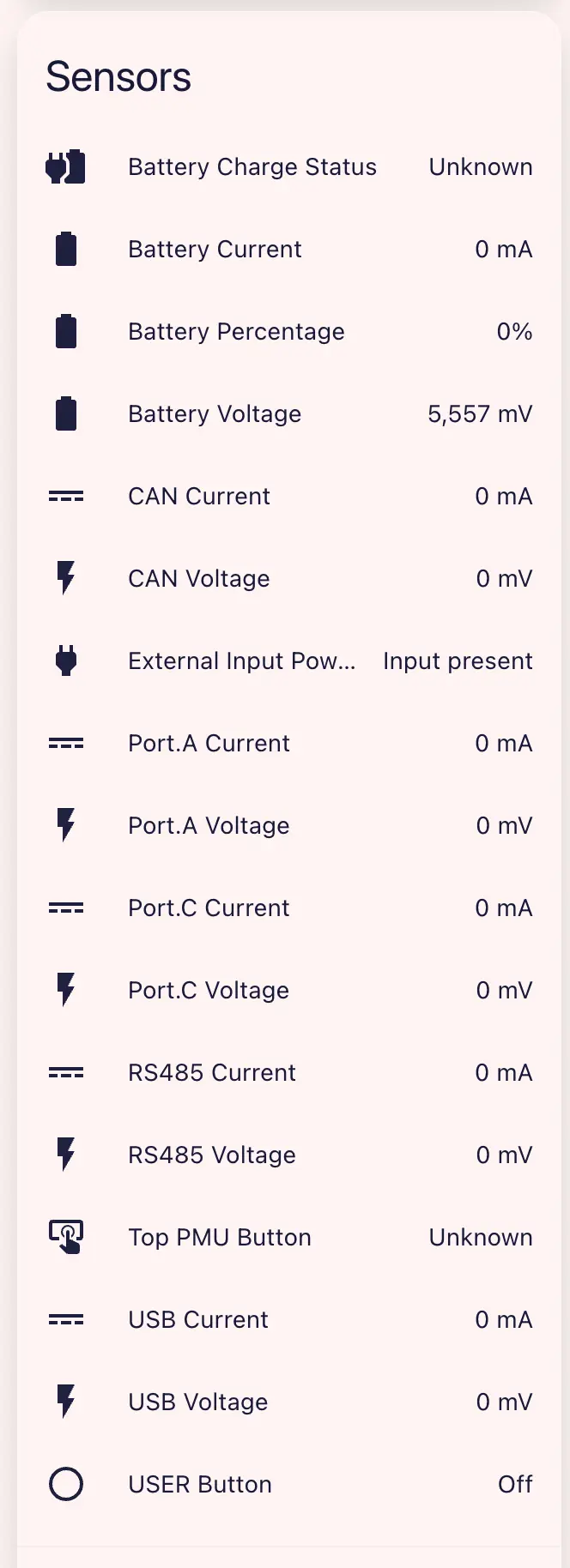
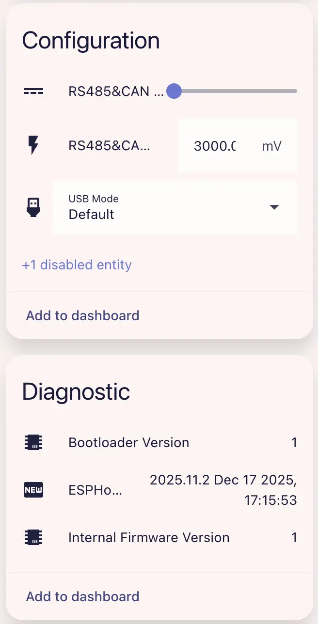
The complete example can control each indicator and power output, and configure the USB mode and RS485/CAN output limits.