Arduino Quick Start
2. Devices & Examples
3. M5Unified
4. M5GFX
5. Extensions
Unit
Atomic
Base
Tab5
IoT
Accessories
Module COMMU Arduino Tutorial
1. Preparations
- Environment Setup: Complete IDE installation by referring to the Arduino IDE Getting Started Tutorial, and install the corresponding board manager and required driver libraries based on the actual development board being used.
- Required Driver Libraries:
- Required Hardware Products:
- CoreS3
- Basic v2.7
- COMMU Module
- Unit ENV-III (This product is only used when testing I2C interface)
2. Important Notes
3. CAN Bus Transceiver Experiment
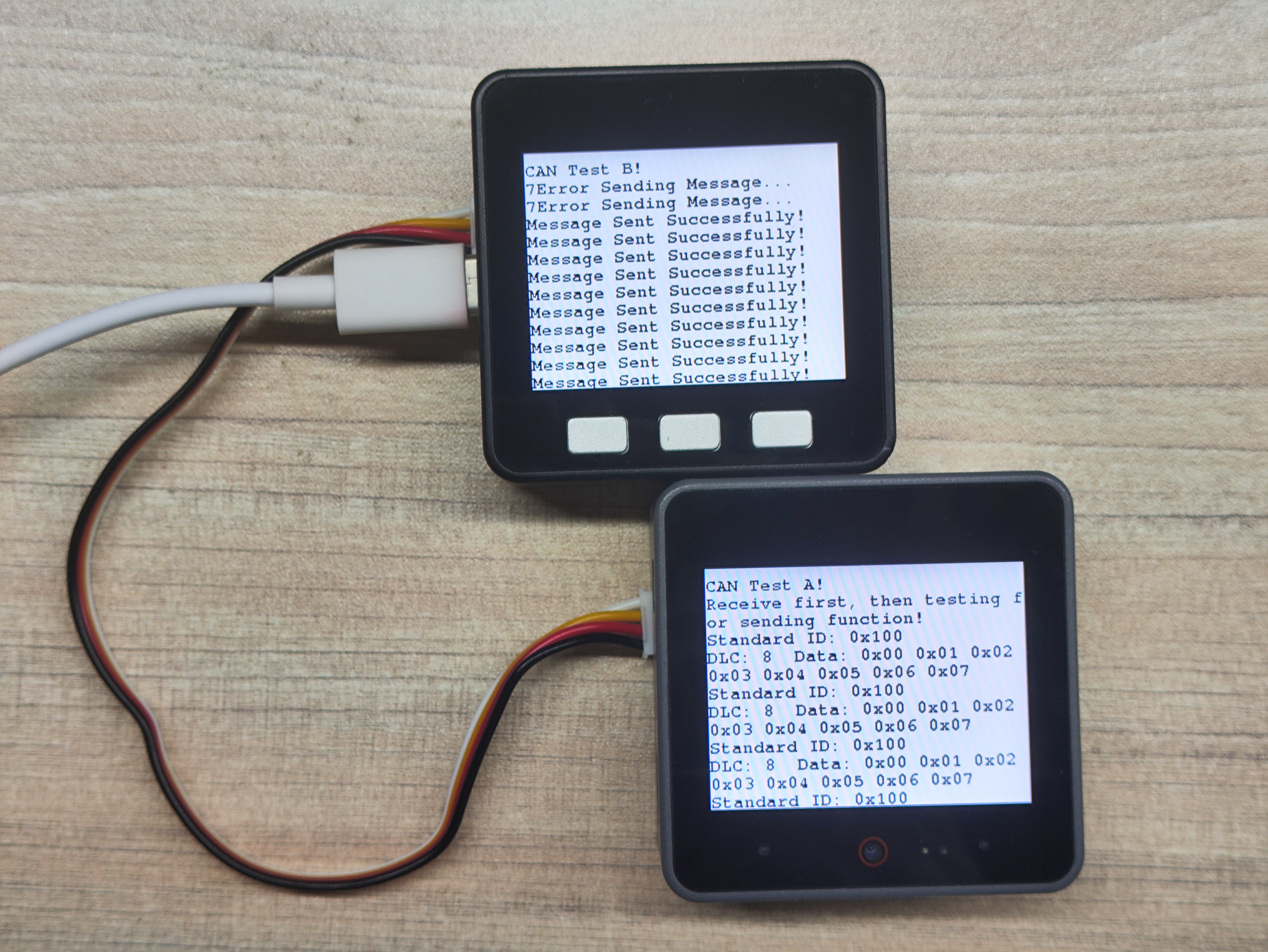
This experiment uses Basic v2.7 as the CAN receiver and CoreS3 as the CAN transmitter. Please modify the INT and CS pin numbers according to actual connections.
Note that CAN bus communication requires successful synchronization between both ends. The message 7Error Sending Message.. seen on the Basic v2.7 host occurs because the transmitter starts before the receiver, causing initial transmission failures before proper acknowledgment from the receiver.
- CAN Receiver Program:
/**
 * @file Commu_can_receiver
 * @author Zovey (liangzhuowei@m5stack.com)
 * @brief
 * @version 0.1
 * @date 2025-06-27
 *
 *
 * @Hardwares: M5CoreS3 + Module COMMU
 * @Dependent Library:
 * M5UnitENV: https://github.com/m5stack/M5Unit-ENV
 * MCP_CAN_lib: https://github.com/coryjfowler/MCP_CAN_lib
 */

#include <M5Unified.h>
#include <mcp_can.h>

byte data[8] = {0x00, 0x01, 0x02, 0x03, 0x04, 0x05, 0x06, 0x07};

long unsigned int rxId;
unsigned char len = 0;
unsigned char rxBuf[8];
char msgString[128];

#define CAN0_INT 13
MCP_CAN CAN0(6);

void init_can();
void test_can();

void setup() {
    M5.begin();
    M5.Power.begin();
    Serial.begin(115200);
    Serial2.begin(9600, SERIAL_8N1, 16, 17);

    M5.Display.fillScreen(WHITE);
    M5.Display.setTextColor(BLACK);
    M5.Display.setFont(&fonts::FreeMonoBold9pt7b);
    delay(500);

    init_can();
    Serial.println("Test CAN...");
}

void loop() {
    test_can();
}

void init_can() {
    M5.Display.setTextSize(1);
    M5.Display.setCursor(0, 10);
    M5.Display.fillScreen(WHITE);
    delay(500);

    M5.Display.printf("CAN Test A!\n");
    M5.Display.printf("Receive first, then testing for sending function!\n");

    if (CAN0.begin(MCP_ANY, CAN_1000KBPS, MCP_8MHZ) == CAN_OK)
        Serial.println("MCP2515 Initialized Successfully!");
    else
        Serial.println("Error Initializing MCP2515...");

    CAN0.setMode(MCP_NORMAL);
    pinMode(CAN0_INT, INPUT);

    Serial.println("MCP2515 Library Receive Example...");
}

void test_can() {
    if (!digitalRead(CAN0_INT)) {
        CAN0.readMsgBuf(&rxId, &len, rxBuf);

        if ((rxId & 0x80000000) == 0x80000000)
            sprintf(msgString, "Extended ID: 0x%.8lX  DLC: %1d  Data:", (rxId & 0x1FFFFFFF), len);
        else
            sprintf(msgString, "Standard ID: 0x%.3lX  \nDLC: %1d  Data:", rxId, len);

        Serial.print(msgString);
        M5.Display.printf(msgString);

        if ((rxId & 0x40000000) == 0x40000000) {
            sprintf(msgString, " REMOTE REQUEST FRAME");
            Serial.print(msgString);
            M5.Display.printf(msgString);
        } else {
            for (byte i = 0; i < len; i++) {
                sprintf(msgString, " 0x%.2X", rxBuf[i]);
                Serial.print(msgString);
                M5.Display.printf(msgString);
            }
        }
        M5.Display.printf("\n");
        Serial.println();
    }
}- CAN Transmitter Program:
/**
 * @file Commu_can_transimmiter
 * @author Zovey (liangzhuowei@m5stack.com)
 * @brief
 * @version 0.1
 * @date 2025-06-27
 *
 *
 * @Hardwares: M5CoreS3 + Module COMMU
 * @Dependent Library:
 * MCP_CAN_lib: https://github.com/coryjfowler/MCP_CAN_lib
 */

#include <M5Unified.h>
#include <mcp_can.h>

byte data[8] = {0x00, 0x01, 0x02, 0x03, 0x04, 0x05, 0x06, 0x07};

long unsigned int rxId;
unsigned char len = 0;
unsigned char rxBuf[8];
char msgString[128];

#define CAN0_INT 15
MCP_CAN CAN0(12);

void init_can();
void test_can();

void setup() {
    M5.begin();
    M5.Power.begin();
    Serial.begin(115200);
    Serial2.begin(9600, SERIAL_8N1, 16, 17);        // Pins of RS485

    M5.Display.fillScreen(WHITE);
    delay(500);
    M5.Display.setTextColor(BLACK);
    M5.Display.setFont(&fonts::FreeMonoBold9pt7b);

    init_can();
    Serial.println("Test CAN...");
}

void loop() {
    delay(500);
    if (M5.BtnA.wasPressed()) {
        M5.Display.clear();
        M5.Display.printf("CAN Test B!\n");
        M5.Display.fillScreen(WHITE);
        init_can();
    }
    test_can();
    M5.update();
}

void init_can() {
    M5.Display.setTextSize(1);
    M5.Display.setCursor(0, 10);
    M5.Display.fillScreen(WHITE);
    M5.Display.printf("CAN Test B!\n");

    if (CAN0.begin(MCP_ANY, CAN_1000KBPS, MCP_8MHZ) == CAN_OK)
        Serial.println("MCP2515 Initialized Successfully!");
    else
        Serial.println("Error Initializing MCP2515...");

    CAN0.setMode(MCP_NORMAL);
}

void test_can() {
    byte sndStat = CAN0.sendMsgBuf(0x100, 0, 8, data);
    if (sndStat == CAN_OK) {
        Serial.println("Message Sent Successfully!");
        M5.Display.printf("Message Sent Successfully!\n");
    } else {
        Serial.printf("%d", sndStat);
        Serial.println("Error Sending Message...");
        M5.Display.printf("%d", sndStat);
        M5.Display.printf("Error Sending Message...\n");
    }
    delay(200);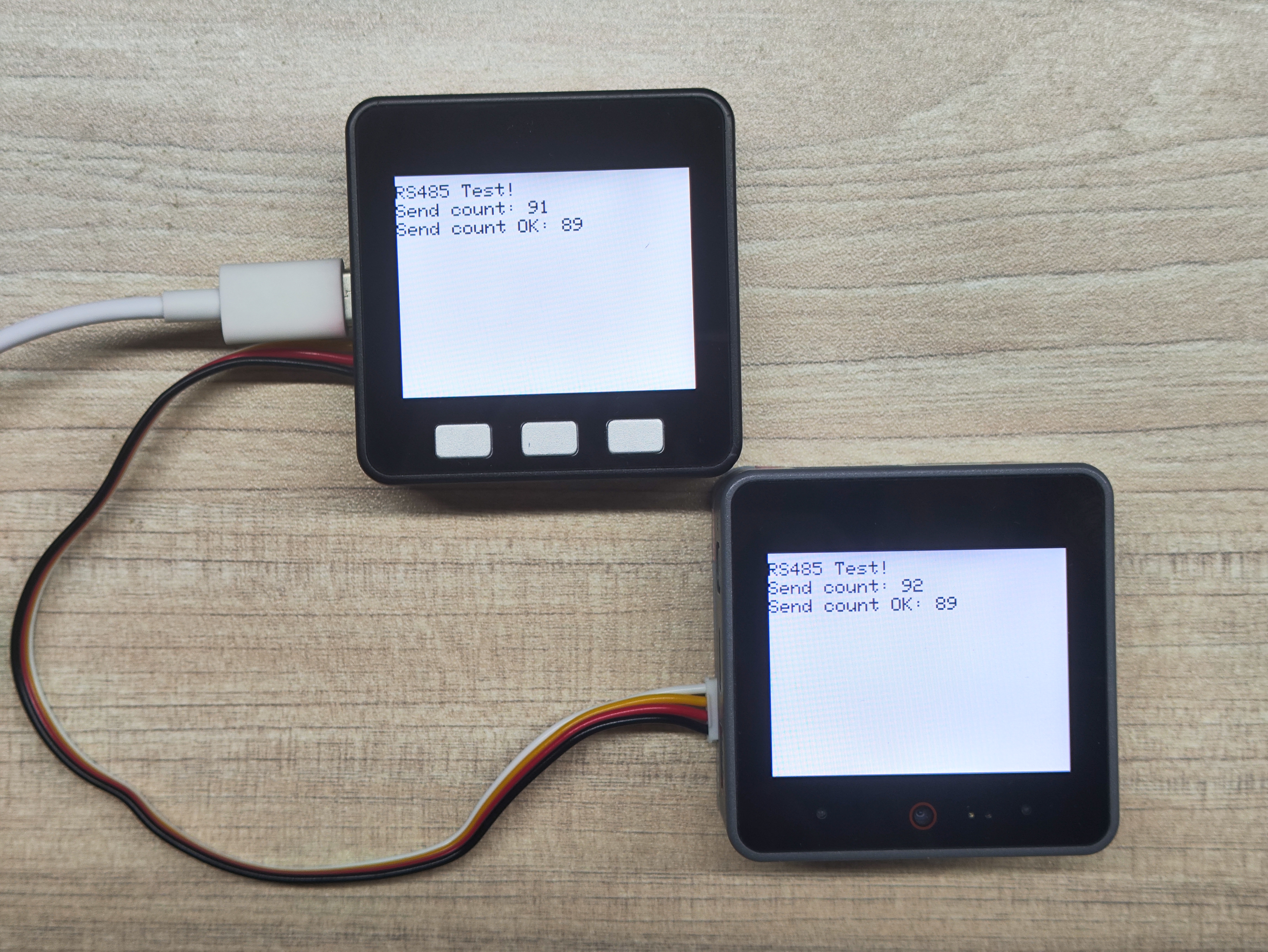
}4. RS485 Transceiver Experiment
This experiment demonstrates RS485 communication between two devices. When uploading to different host devices, please modify the pin definitions in the example program according to actual connection requirements.
- RS485 Transceiver Program:
/**
 * @file RS485_Test
 * @author Zovey (liangzhuowei@m5stack.com)
 * @brief
 * @version 0.1
 * @date 2025-06-27
 *
 *
 * @Hardwares: M5CoreBasic + M5CoreS3 + Module COMMU
 */

#include <M5Unified.h>

// RS485 data buffer
// FH  len  fun   data   CRC
// 01 aa 00 09 00 01 00 01 b6
char uart_buffer[9] = {0x01, 0xaa, 0x00, 0x09, 0x00, 0x01, 0x00, 0x01, 0xb6};
char comchar;
char Num       = 0;
int Send_Count = 0;
int Send_OK    = 0;
int RECcheck   = 0;
char stringnum = 0;

typedef union {
    struct { char buff[10]; };
    struct { short frame; short datalength; short function; short data; char check; };
    struct {
        char framelow;
        char framehigh;
        char datalengthlow;
        char datalengthhigh;
        char functionhigh;
        char functionlow;
        char datahigh;
        char datalow;
    };
} uart_data;

uart_data UART_DATA    = {0};
uart_data UART_RECDATA = {0};

void init_rs485();
void test_rs485();
void updatedata();

void setup() {
    M5.begin();
    M5.Power.begin();
    Serial.begin(115200);
    Serial2.begin(9600, SERIAL_8N1, 18, 17);

    M5.Display.fillScreen(WHITE);
    delay(500);
    M5.Display.setTextColor(BLACK);

    init_rs485();
    Serial.println("Test RS485...");
}

void loop() {
    if (M5.BtnA.wasPressed()) {
        M5.Display.clear();
        M5.Display.printf("RS485 Test!\n");
        M5.Display.fillScreen(WHITE);
        init_rs485();
        Serial.println("Test RS485...");
    }
    test_rs485();
    M5.update();
    delay(1000);
}

void init_rs485() {
    M5.Display.fillScreen(WHITE);
    delay(500);

    M5.Display.setTextSize(2);
    M5.Display.setCursor(0, 10);
    M5.Display.printf("RS485 Test!\n");
    Serial.println("RS485 Test A!\n");
    memcpy(UART_DATA.buff, uart_buffer, 9);

    updatedata();
}

void updatedata() {
    Send_Count = (Send_Count + 1) & 0xffff;
    UART_DATA.datahigh = (Send_Count & 0xff00) >> 8;
    UART_DATA.datalow  = Send_Count & 0xff;
    UART_DATA.check = UART_DATA.framelow + UART_DATA.framehigh + UART_DATA.datalengthlow + UART_DATA.datalengthhigh +
                      UART_DATA.functionlow + UART_DATA.functionhigh + UART_DATA.datalow + UART_DATA.datahigh;

    for (stringnum = 0; stringnum < 9; stringnum++) {
        Serial2.print(UART_DATA.buff[stringnum]);
        Serial.print(UART_DATA.buff[stringnum]);
        Serial.print(" ");
    }

    M5.Display.fillRect(0, 30, 300, 20, WHITE);
    M5.Display.setCursor(0, 30);
    M5.Display.printf("Send count: %d", Send_Count);

    M5.Display.fillRect(0, 50, 300, 20, WHITE);
    M5.Display.setCursor(0, 50);
    M5.Display.printf("Send count OK: %d\r\n", Send_OK);
}

void test_rs485() {
    while (Serial2.available() > 0) {
        Num = Serial2.readBytes(uart_buffer, 9);
        if (Num == 9) {
            memcpy(UART_RECDATA.buff, uart_buffer, 9);
            RECcheck = UART_RECDATA.framelow + UART_RECDATA.framehigh + UART_RECDATA.datalengthlow +
                       UART_RECDATA.datalengthhigh + UART_RECDATA.functionlow + UART_RECDATA.functionhigh +
                       UART_RECDATA.datalow + UART_RECDATA.datahigh;
            if (UART_RECDATA.check == (RECcheck & 0xff)) {
                Send_OK++;
            }
        }
        updatedata();
    }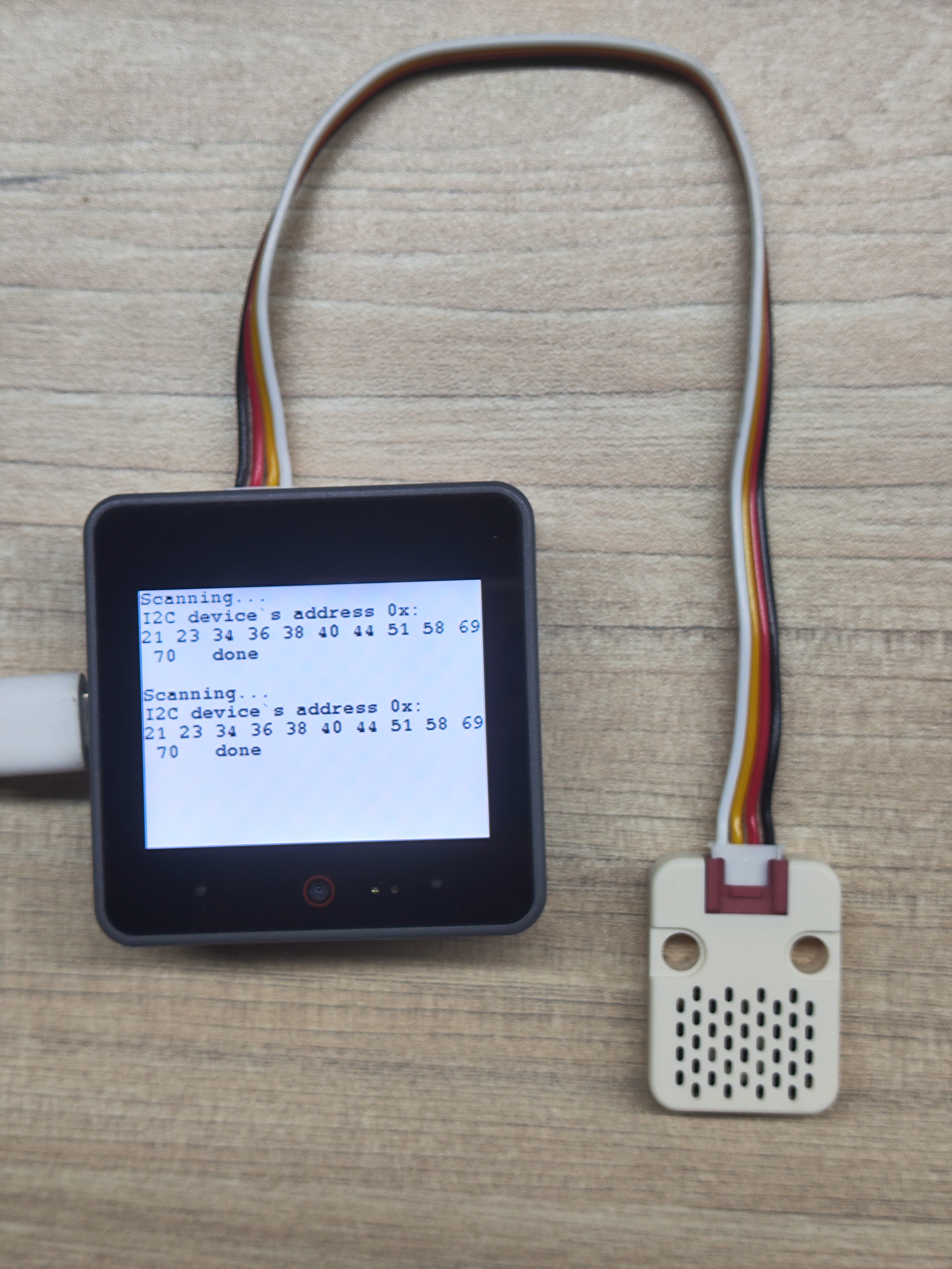
}5. I2C Interface Experiment
This experiment demonstrates peripheral device driving via I2C interface. When uploading to different host devices, please modify the pin definitions in the example program according to actual connection requirements. For the I2C peripheral driving experiment in this tutorial, Unit ENV-III is used as an example, while in the I2C communication experiment, any I2C peripheral can be used to obtain the address.
- I2C Address Scanning Experiment:
/**
 * @file IIC_Test
 * @author Zovey (liangzhuowei@m5stack.com)
 * @brief
 * @version 0.1
 * @date 2025-06-27
 *
 * @Hardwares: M5CoreS3 + Module COMMU
 */

#include "M5Unified.h"
#include <Wire.h>

uint8_t count = 0;

void setup() {
    M5.begin();
    Serial.begin(115200);
    Serial.println("I2C Address Scanning ...");
    Wire.begin(12, 11);
    M5.Display.fillScreen(WHITE);
    M5.Display.setTextColor(BLACK);
    M5.Display.setFont(&fonts::FreeMonoBold9pt7b);
    delay(500);
}

void loop() {
    byte error, address;
    int nDevices = 0;

    Serial.println("Scanning...");
    M5.Display.println("Scanning...");
    M5.Display.print("I2C device`s address 0x:\r\n");
    Serial.print("I2C device found at address 0x\r\n");
    for (address = 1; address < 127; address++) {
    Wire.beginTransmission(address); // Start transmitting to the specified address
    error = Wire.endTransmission(); // Check if there is any device response

    if (error == 0) {
        if (address < 16) Serial.print("0");
        Serial.println(address, HEX); // Output device address (hexadecimal)
        M5.Display.printf("%02X ",address);
        nDevices++;
    } else if (error == 4) {
        Serial.print("Unknown error at address 0x");
        if (address < 16) Serial.print("0");
        Serial.println(address, HEX);
        }
    }

    if (nDevices == 0) {
    Serial.println("No I2C devices found\n");
    M5.Display.println("No I2C devices found\n");
    } else {
    Serial.println("done\n");
    M5.Display.println("  done\n");
    }
    delay(5000); // Re-scan every five seconds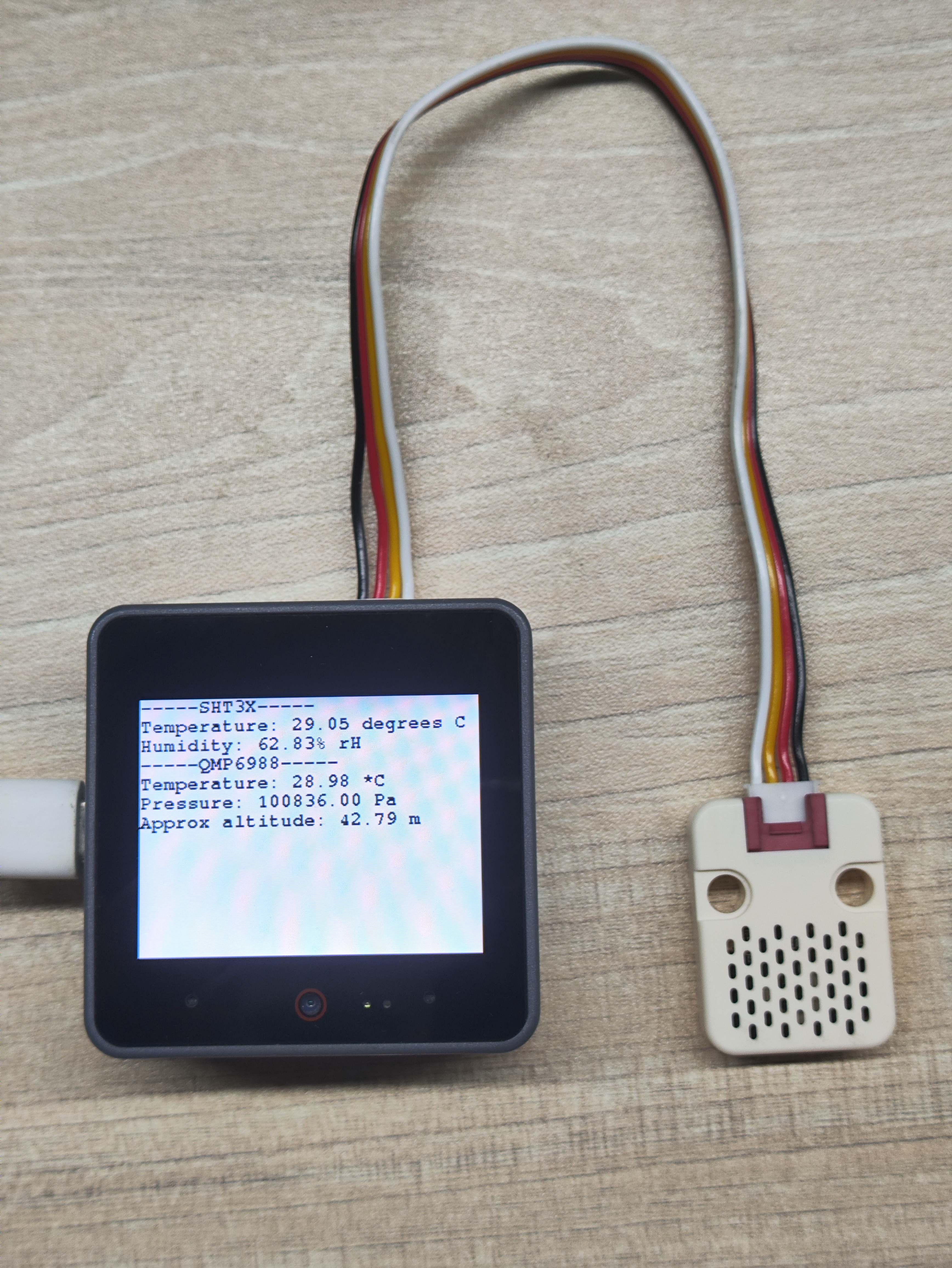
}- I2C Peripheral Driving Experiment:
/**
 * @file IIC_Test
 * @author Zovey (liangzhuowei@m5stack.com)
 * @brief
 * @version 0.1
 * @date 2025-06-27
 *
 * @Hardwares: M5CoreS3 + Unit ENV_III + Module COMMU
 * @Dependent Library:
 * M5UnitENV: https://github.com/m5stack/M5Unit-ENV
 */

#include "M5Unified.h"
#include "M5UnitENV.h"

SHT3X sht3x;
QMP6988 qmp;

void setup() {
    M5.begin();
    Serial.begin(115200);

    M5.Display.fillScreen(WHITE);
    M5.Display.setTextColor(BLACK);
    M5.Display.setFont(&fonts::FreeMonoBold9pt7b);
    delay(500);

    if (!qmp.begin(&Wire, QMP6988_SLAVE_ADDRESS_L, 12, 11, 400000U)) {
        Serial.println("Couldn't find QMP6988");
        while (1) delay(1);
    }

    if (!sht3x.begin(&Wire, SHT3X_I2C_ADDR, 12, 11, 400000U)) {
        Serial.println("Couldn't find SHT3X");
        while (1) delay(1);
    }
}

void printSHT3X(const SHT3X& sht) {
    Serial.println("-----SHT3X-----");
    Serial.printf("Temperature: %.2f degrees C\nHumidity: %.2f%% rH\n",
                  sht.cTemp, sht.humidity);    M5.Display.fillScreen(WHITE);
    M5.Display.setCursor(0, 0);
    M5.Display.printf("-----SHT3X-----\r\n");
    M5.Display.printf("Temperature: %.2f degrees C\nHumidity: %.2f%% rH\n",
                      sht.cTemp, sht.humidity);
}

void printQMP6988(const QMP6988& qmp) {
    Serial.println("-----QMP6988-----");
    Serial.printf("Temperature: %.2f *C\nPressure: %.2f Pa\nApprox altitude: %.2f m\n",
                  qmp.cTemp, qmp.pressure, qmp.altitude);
    M5.Display.printf("-----QMP6988-----\r\n");
    M5.Display.printf("Temperature: %.2f *C\nPressure: %.2f Pa\nApprox altitude: %.2f m\n",
                     qmp.cTemp, qmp.pressure, qmp.altitude);
}

void loop() {
    if (sht3x.update()) printSHT3X(sht3x);
    if (qmp.update())   printQMP6988(qmp);
    delay(1000);
}6. Compile and Upload
Download Mode: Different devices need to enter download mode before programming. This step may vary depending on the main control device. For details, please refer to the device programming tutorial list at the bottom of the Arduino IDE Getting Started Tutorial page for specific instructions.
For CoreS3: Press and hold the reset button (about 2 seconds) until the internal green LED lights up, then release. The device will now enter download mode and wait for programming.
.gif)
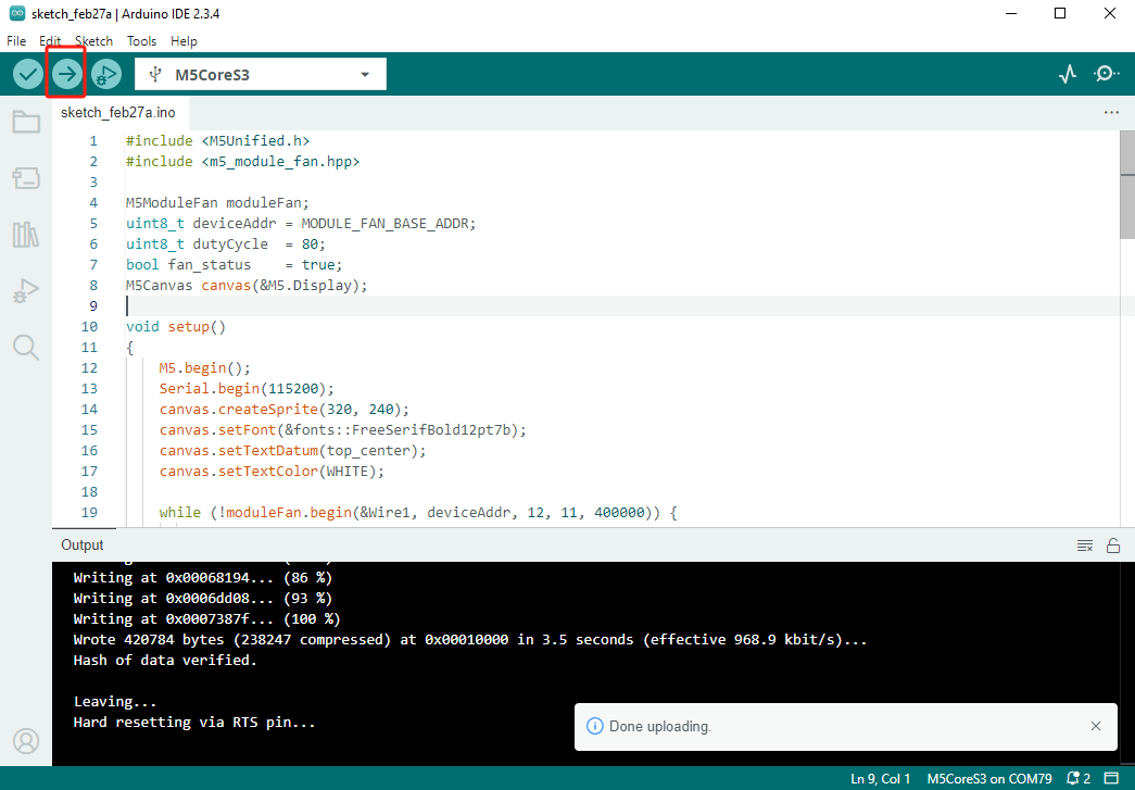
- Select the device port and click the upload button in the upper left corner of Arduino IDE. Wait for the program to complete compilation and upload to the device.