Home Assistant
Media Player
Expansion
Sensor
Station-Bat Controller Home Assistant Integration
This chapter explains how to integrate Station-Bat into Home Assistant.
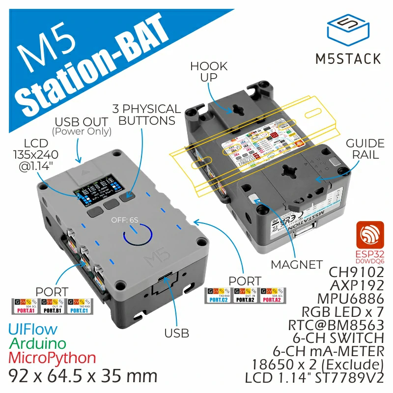
1. Preparation
Environment Setup
- Refer to the official Home Assistant documentation to install Home Assistant.
- Refer to the official ESPHome documentation to install the ESPHome Device Builder add-on. (Note: This tutorial is based on
ESPHome 2026.2.4. If compilation errors occur, switch to this version for verification.)
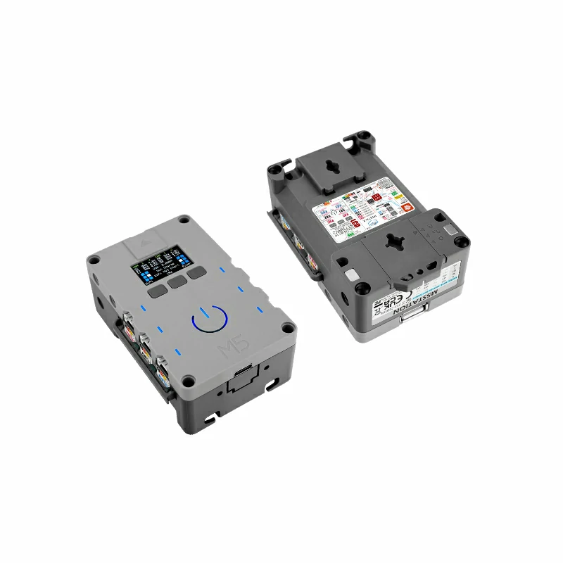
Hardware Products
2. Online Flashing
Click the Online Flashing button below and follow the prompts to flash the firmware and configure Wi-Fi, allowing you to quickly connect Station-Bat to Home Assistant.
For detailed flashing and configuration instructions, refer to Online ESPHome Firmware Flashing and Configuration.
After using online flashing, you do not need to perform the "Firmware Compilation & Flashing" steps. Proceed directly to 4. Getting Started.
3. Firmware Compilation & Flashing
This section explains how to recompile the project from the yaml configuration file for secondary development, feature modifications, or new functionality.
Create Device
- Click the green button in the bottom right corner to create a device.
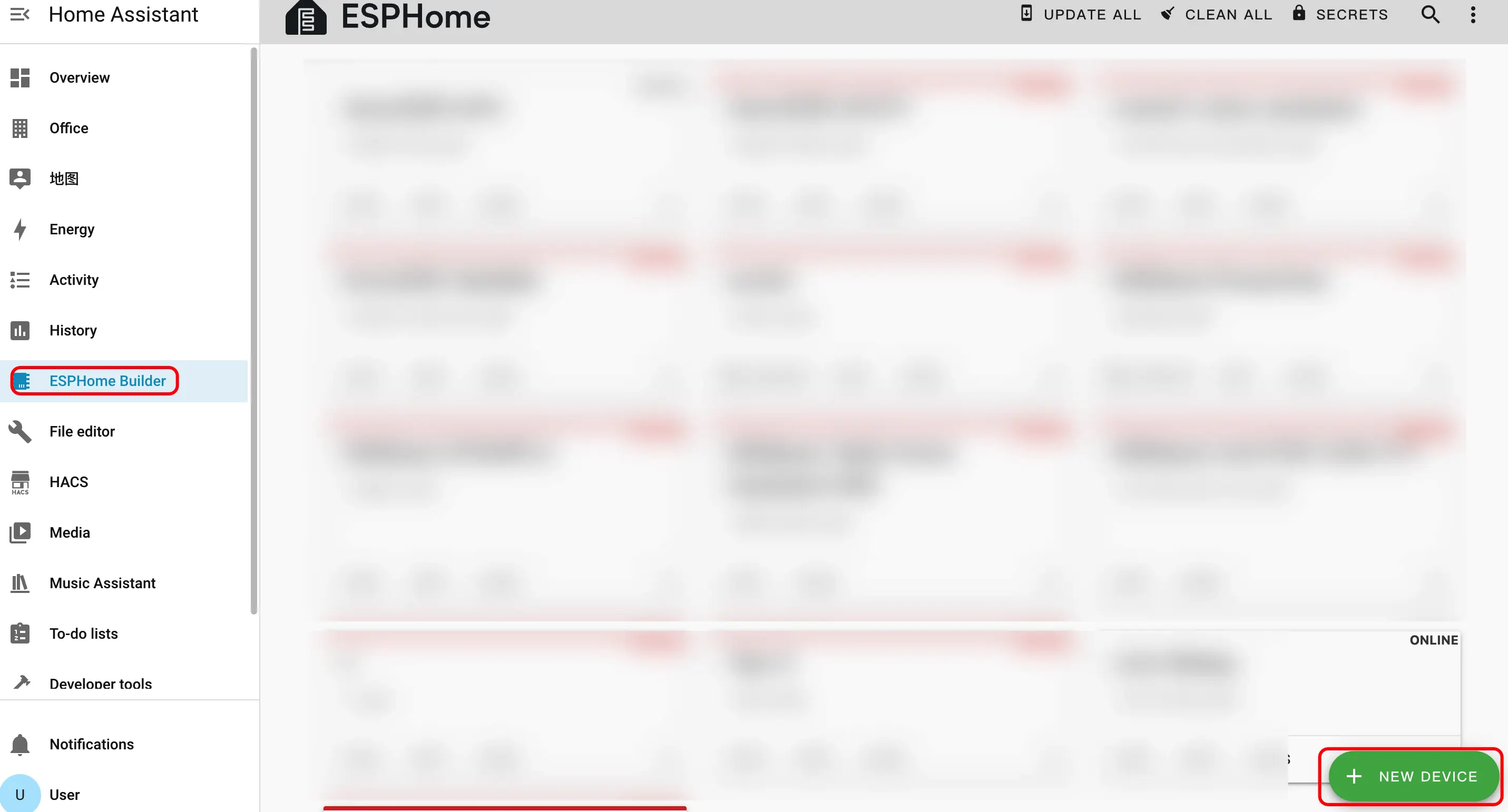
- Click
CONTINUE.
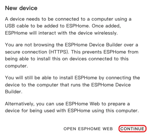
- Click
New Device Setup.
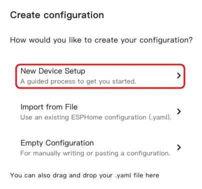
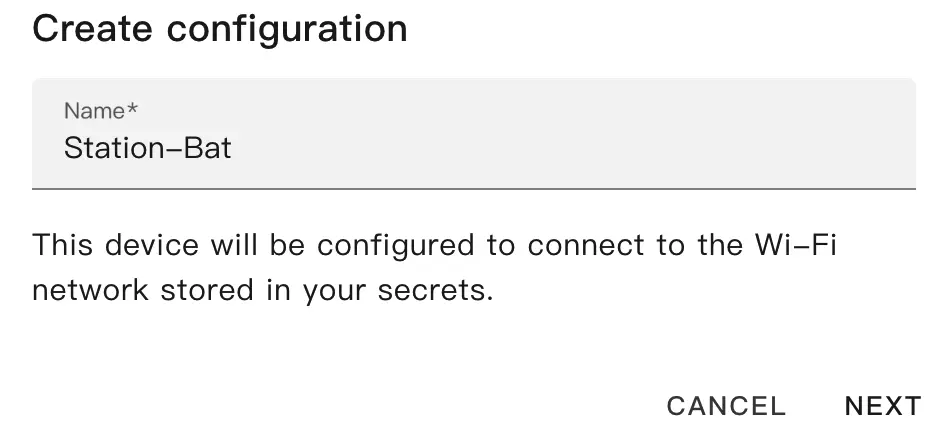
- Enter the device name and click
NEXT.
- Select
ESP32.
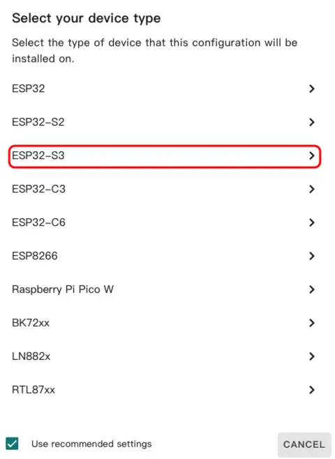
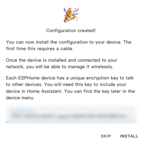
- Click
SKIPto skip the wizard.
Modify Configuration
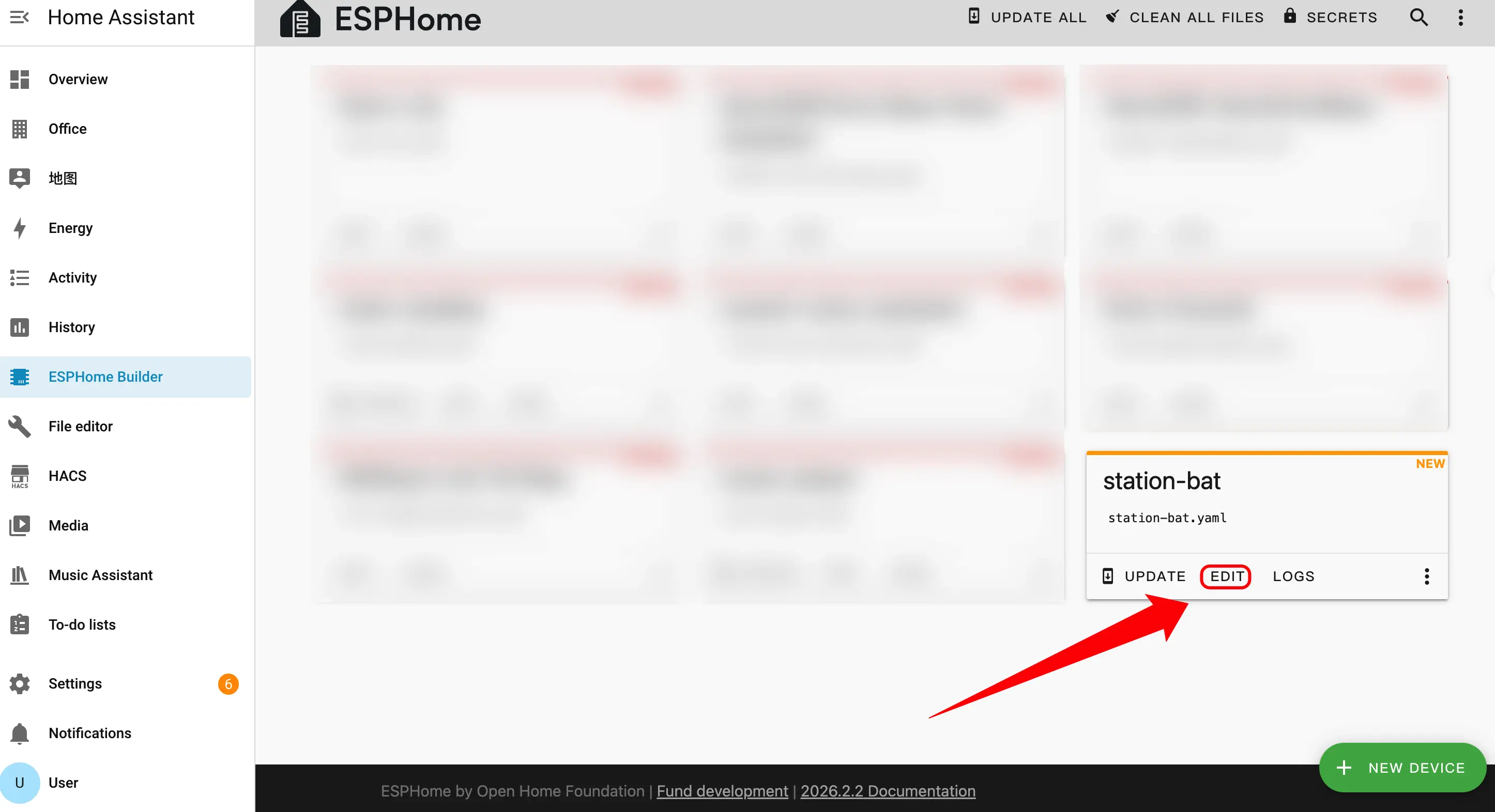
- Click
EDITto customize the device functionality via the YAML file.
The following are the core parts of the configuration, accompanied by corresponding descriptions and reference links.
Boot Configuration
- Add boot initialization logic to ensure the time can be read from the RTC during startup.
esphome:
  name: station-bat
  friendly_name: station-bat
  on_boot:
    - priority: 600
      then:
- bm8563.read_time:External Components
- Add External Components configuration. The
m5station_axp192component provides power management and battery level detection support for Station-Bat.
external_components:
  - source: github://m5stack/esphome-yaml/components
    components: [m5station_axp192]
refresh: 0sI2C Bus Configuration
- Add I2C component. The I2C bus is shared by the IMU, power management chip, and current/voltage monitoring chips.
i2c:
  - id: i2c_bus
    sda: GPIO21
scl: GPIO22SPI Bus Configuration
- Add SPI component. The SPI bus is used to drive the ST7789V display screen.
spi:
  clk_pin: GPIO18
mosi_pin: GPIO23Sensor Configuration
- Add Sensor component.
- Add MPU6886 IMU sensor for accelerometer, gyroscope, and temperature data collection.
- Add two INA3221 current/voltage monitoring chips, covering a total of 6 channels (A1/A2, B1/B2, C1/C2).
- The
m5station_axp192sensor is provided by the external component introduced earlier, used for battery level and other power-related information.
sensor:
  - platform: mpu6886
    i2c_id: i2c_bus
    accel_x:
      name: "MPU6886 Accel X"
      id: imu_ax
    accel_y:
      name: "MPU6886 Accel Y"
      id: imu_ay
    accel_z:
      name: "MPU6886 Accel z"
      id: imu_az
    gyro_x:
      name: "MPU6886 Gyro X"
    gyro_y:
      name: "MPU6886 Gyro Y"
    gyro_z:
      name: "MPU6886 Gyro z"
    temperature:
      name: "MPU6886 Temperature"
      id: imu_temp
    update_interval: 5s

  - platform: m5station_axp192
    id: pmu
    i2c_id: i2c_bus
    battery_level:
      name: "M5Station Battery Level"
      id: bat_level
    update_interval: 60s
    brightness: 0.8

  - platform: ina3221
    id: ina1
    i2c_id: i2c_bus
    address: 0x40
    update_interval: 1s
    channel_1:
      shunt_resistance: 0.01
      bus_voltage:
        name: "P.A1 Bus Voltage"
        id: v_a1
      current:
        name: "P.A1 Current"
        id: i_a1
    channel_2:
      shunt_resistance: 0.01
      bus_voltage:
        name: "P.A2 Bus Voltage"
        id: v_a2
      current:
        name: "P.A2 Current"
        id: i_a2
    channel_3:
      shunt_resistance: 0.01
      bus_voltage:
        name: "P.B1 Bus Voltage"
        id: v_b1
      current:
        name: "P.B1 Current"
        id: i_b1

  - platform: ina3221
    id: ina2
    i2c_id: i2c_bus
    address: 0x41
    update_interval: 1s
    channel_1:
      shunt_resistance: 0.01
      bus_voltage:
        name: "P.B2 Bus Voltage"
        id: v_b2
      current:
        name: "P.B2 Current"
        id: i_b2
    channel_2:
      shunt_resistance: 0.01
      bus_voltage:
        name: "P.C1 Bus Voltage"
        id: v_c1
      current:
        name: "P.C1 Current"
        id: i_c1
    channel_3:
      shunt_resistance: 0.01
      bus_voltage:
        name: "P.C2 Bus Voltage"
        id: v_c2
      current:
        name: "P.C2 Current"
id: i_c2Binary Sensor Configuration
- Add Binary Sensor component. The three physical buttons on the panel are mapped to GPIO37, GPIO38, and GPIO39 respectively.
binary_sensor:
  - platform: gpio
    name: "Button1"
    pin:
      number: GPIO37
      inverted: true
  - platform: gpio
    name: "Button2"
    pin:
      number: GPIO38
      inverted: true
  - platform: gpio
    name: "Button3"
    pin:
      number: GPIO39
inverted: trueSwitch Configuration
- Add Switch component. The LCD backlight is controlled via the AXP192 power management chip, and the USB power output is controlled via GPIO12.
switch:
  - platform: template
    name: "LCD Backlight"
    id: lcd_backlight
    lambda: |-
      return true;
    restore_mode: ALWAYS_ON
    turn_on_action:
      - lambda: |-
          id(pmu).set_backlight(true);
    turn_off_action:
      - lambda: |-
          id(pmu).set_backlight(false);

  - platform: gpio
    name: "USB Power"
    id: usb_power
pin: GPIO12Time Configuration
- Add Time component.
- Add BM8563 RTC component. The BM8563 is responsible for keeping time when offline, synchronizes time from Home Assistant after connection, and restores to the RTC when the device restarts.
time:
  - platform: bm8563
    id: bm8563_time
    update_interval: never

  - platform: homeassistant
    id: ha_time
    on_time_sync:
      then:
- bm8563.write_time:Light Configuration
- Add Light component. Station-Bat features 7 onboard WS2812 RGB LEDs driven via GPIO4.
light:
  - platform: esp32_rmt_led_strip
    rgb_order: GRB
    pin: GPIO4
    num_leds: 7
    chipset: ws2812
name: "My Light"Display Configuration
- Add Display component.
- Add ST7789V driver for the 1.14-inch IPS screen display. The
lambdablock defines specific drawing content—refer to the configuration file in the link below for a full example.
display:
  - platform: st7789v
    model: CUSTOM
    width: 135
    height: 240
    offset_height: 52
    offset_width: 40
    cs_pin: GPIO5
    dc_pin: GPIO19
    reset_pin: GPIO15
    rotation: 90
    update_interval: 1s
    lambda: |-
      // Define your display content here
// See the complete example for a full implementationBuild Firmware
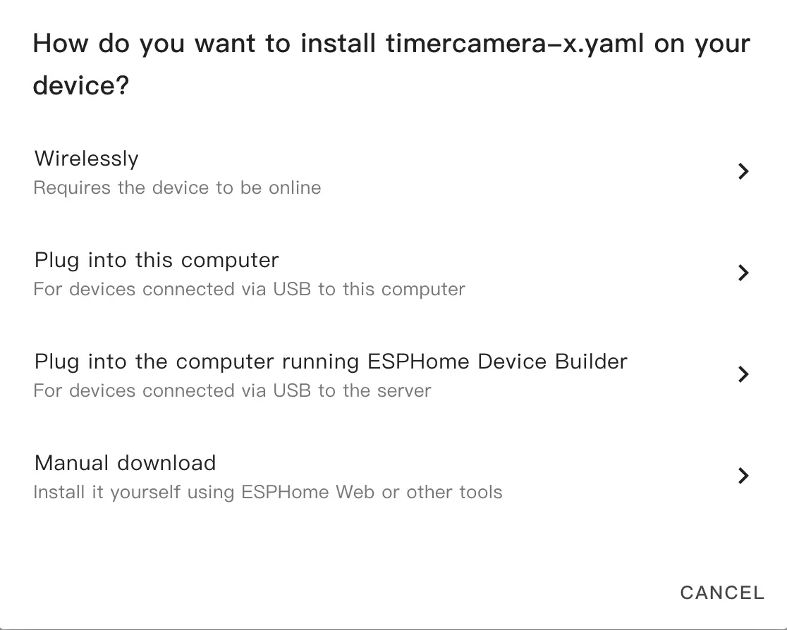
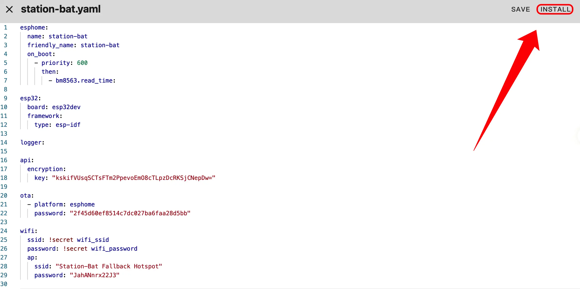
- After modifying, click
SAVEandINSTALLin the top right corner, then selectManual Downloadin the pop-up dialog to download manually.
- Click
INSTALLand wait for the firmware compilation to complete.
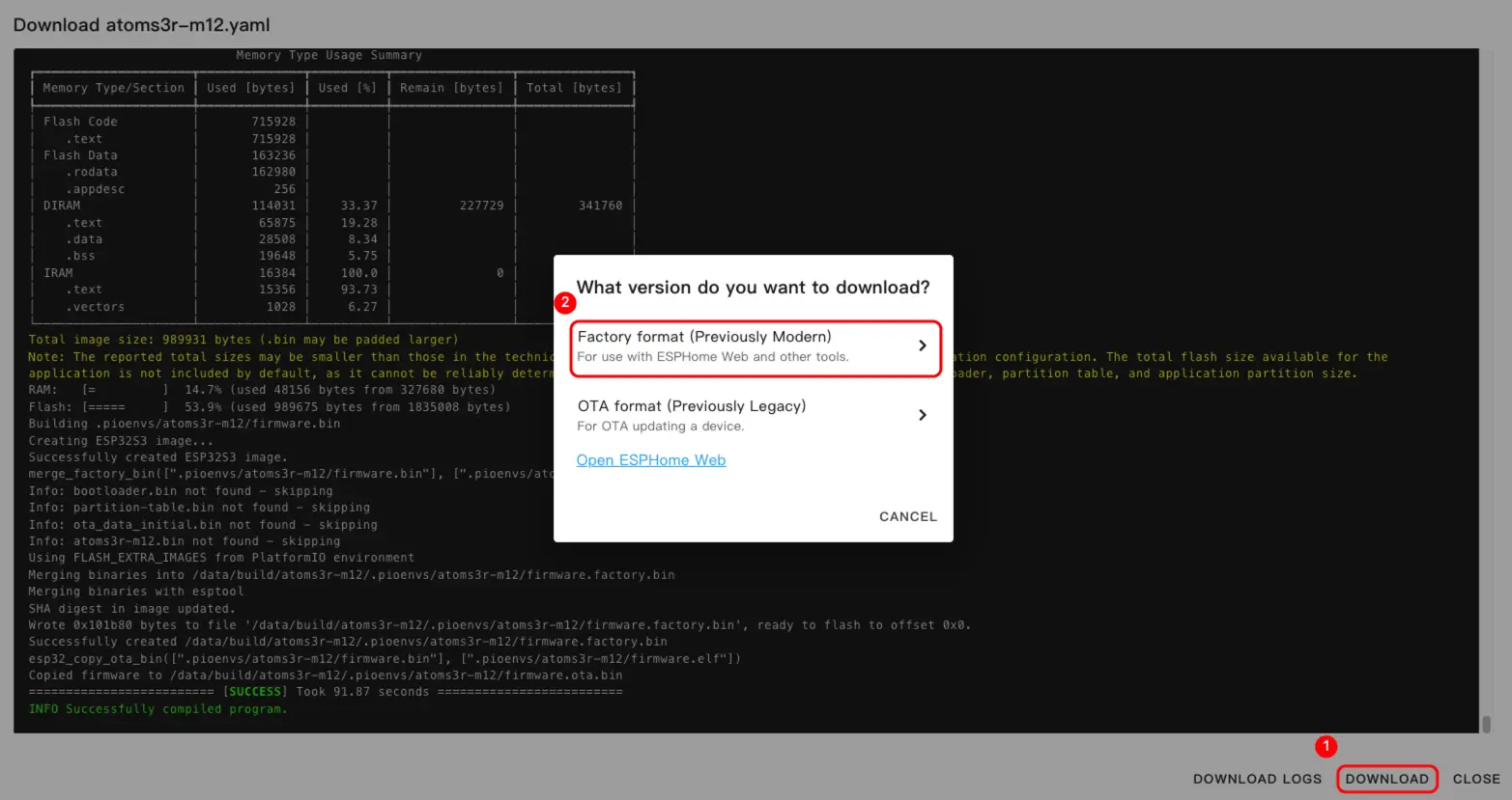
- Once compilation is complete, click Download and select the
Factory format (Previously Modern)format.
Flash Firmware
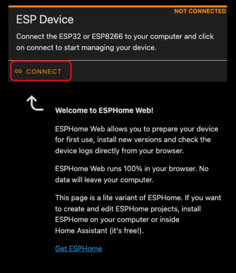
- Connect the device to the host using a USB Type-C cable, open ESPHome Web, and click
CONNECTto link the device.
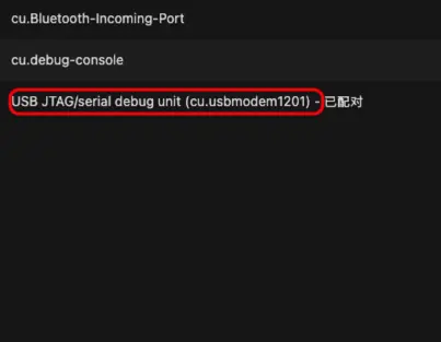
- Select the corresponding serial port number from the pop-up list.
- Click
INSTALL.
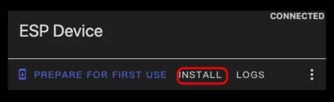
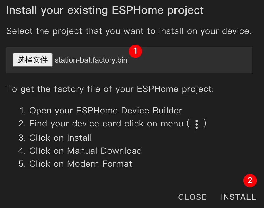
- Select the previously compiled firmware file for flashing.
4. Getting Started
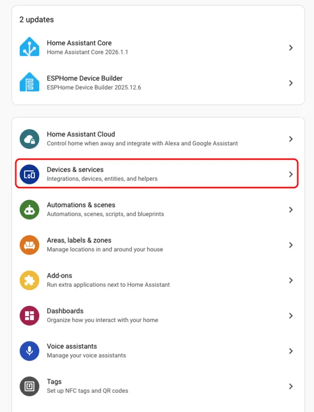
- In Home Assistant, click
Settings→Devices & Servicesto view the device list.
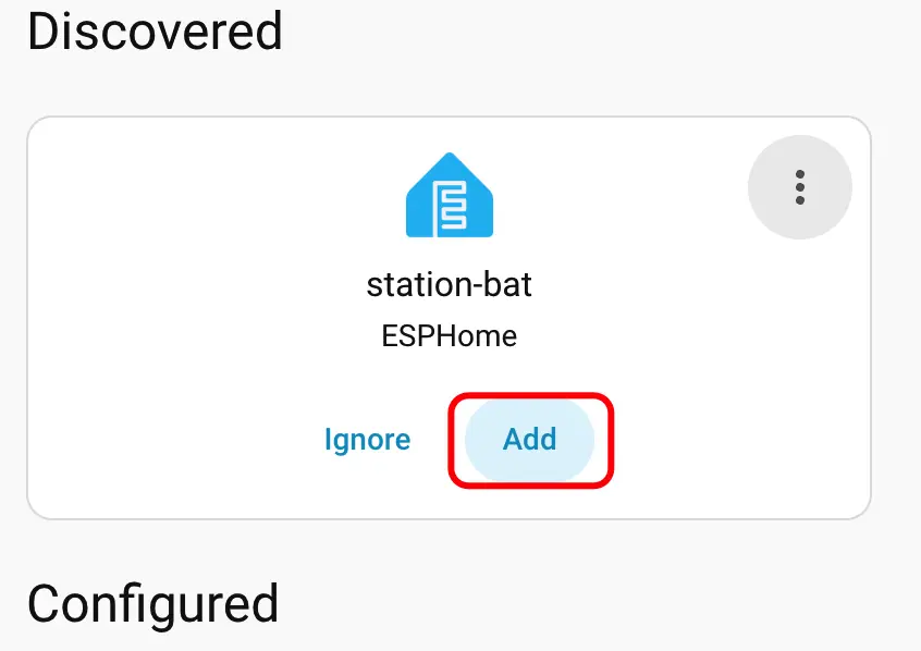
- The corresponding device can be seen in the
Discoveredarea; clickCONFIGUREto complete the addition.
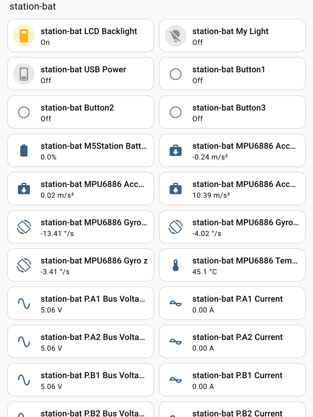
- Once added, various sensor data will be correctly displayed.
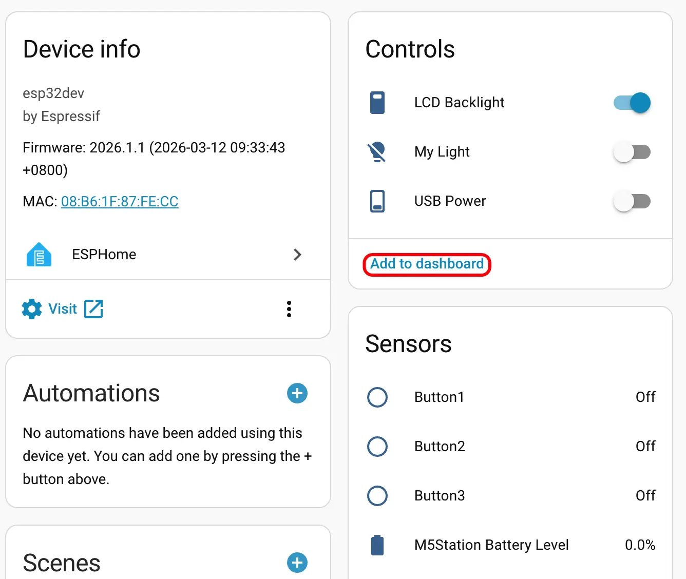
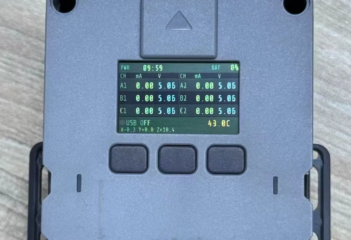
- Finally, add these entities to the Dashboard; the effect is shown in the image below.