

Home Assistant
传感器
Dial Home Assistant 集成
本教程将使用 M5Dial v1.1 开发板集成到 Home Assistant 中,通过其旋钮编码器、NFC 读卡器和蜂鸣器实现智能家居控制。

1. 准备工作
- 硬件
- 1 x M5Dial v1.1
- 1 x USB Type-C 数据线
- 1 x Home Assistant 主机(服务器、迷你 PC、NAS 等)
- 软件与版本
- ESPHome Device Builder 2026.4.0 或更高版本
2. 创建设备
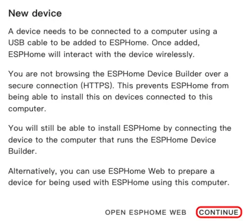
- 打开 ESPHome 仪表盘。如果出现初始向导界面,点击
CONTINUE。
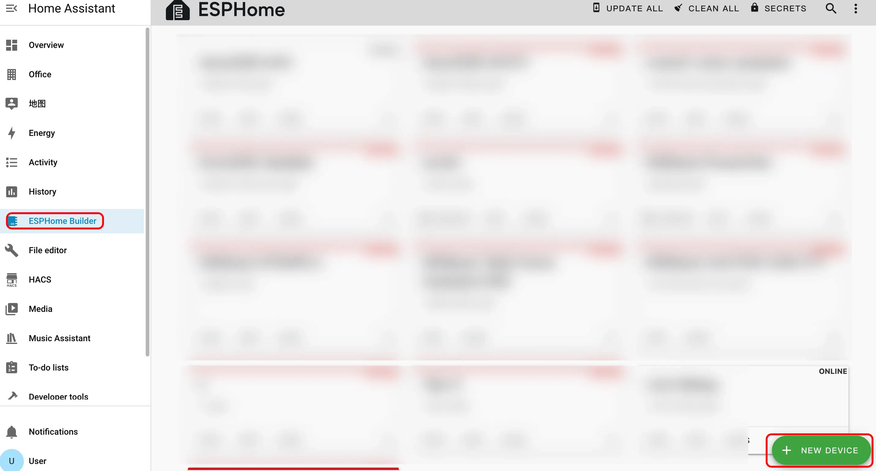
- 点击右下角的绿色 + 按钮创建新设备。
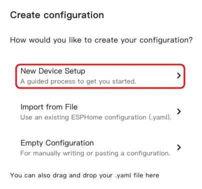
- 点击
New Device Setup进入设备创建向导。
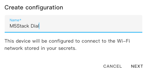
- 输入设备名称,然后点击
NEXT。
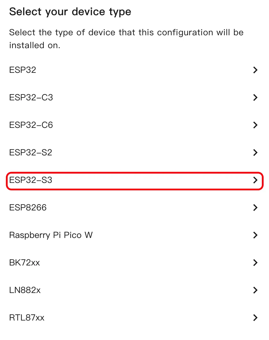
- 选择设备类型,点击
ESP32S3。
- 点击
SKIP跳过加密密钥设置。
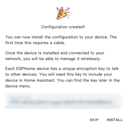
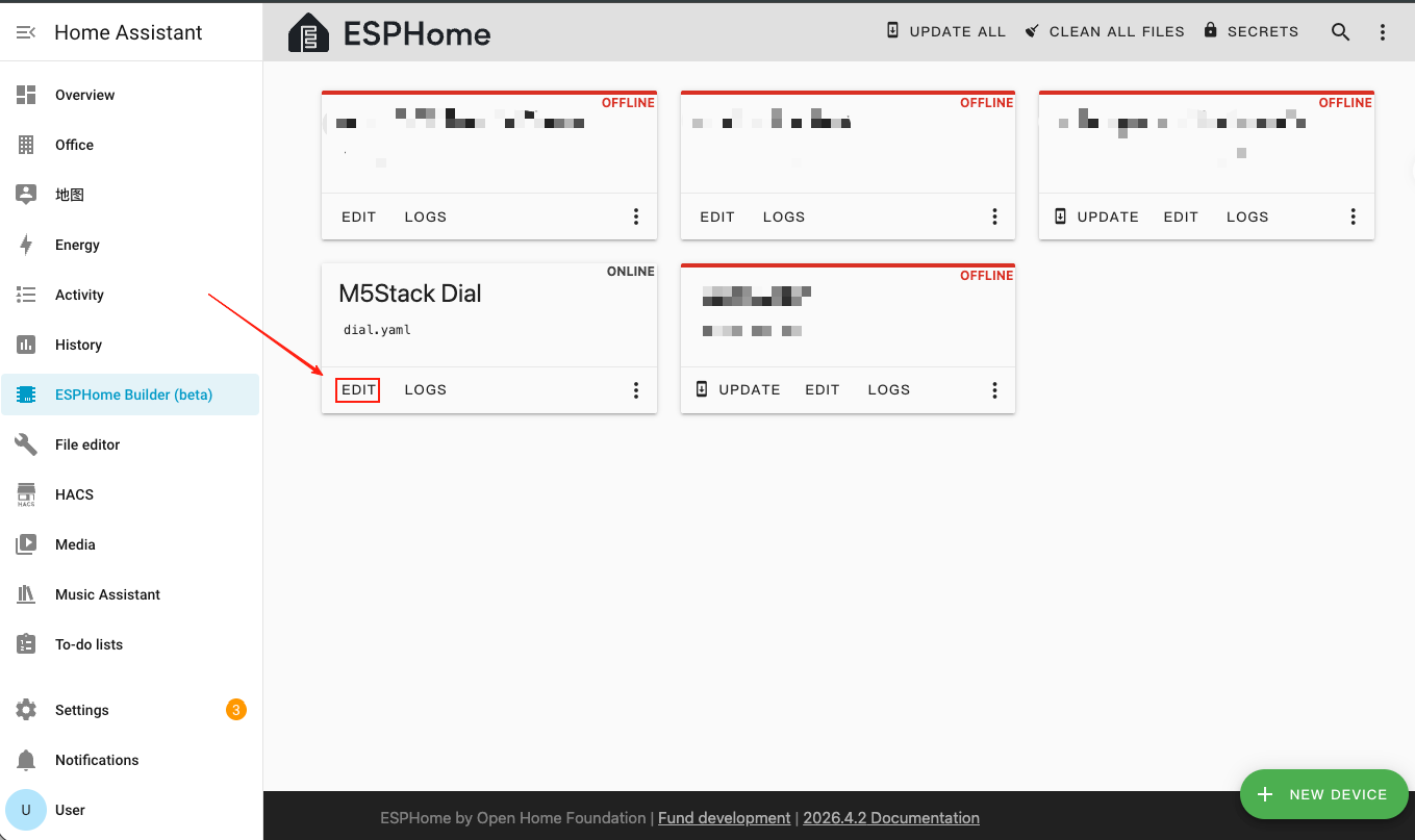
- 点击
EDIT打开 YAML 编辑器,自定义设备配置。
3. 设备配置
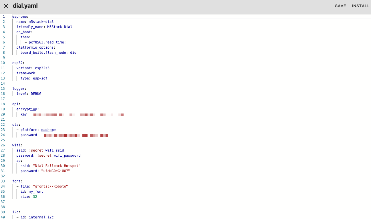
3.1 基础配置
esphome:
  name: m5stack-dial
  friendly_name: M5Stack Dial
  on_boot:
    then:
      - pcf8563.read_time:
  platformio_options:
    board_build.flash_mode: dio

esp32:
  variant: esp32s3
  framework:
    type: esp-idf

logger:
  level: DEBUG

api:
  encryption:
    key: "your_encryption_key"

ota:
  - platform: esphome
    password: "your_ota_password"

wifi:
  ssid: !secret wifi_ssid
  password: !secret wifi_password
  ap:
    ssid: "Dial Fallback Hotspot"
    password: "your_fallback_password"

font:
  - file: "gfonts://Roboto"
    id: my_font
size: 32主要参数说明:
| 参数 | 值 | 说明 |
|---|---|---|
framework.type | esp-idf | 使用 ESP-IDF 框架以获得更好的性能和稳定性。 |
platformio_options | board_build.flash_mode: dio | ESP32-S3 的 Flash 模式配置。 |
on_boot | pcf8563.read_time | 启动时读取 RTC 时间以初始化系统时钟。 |
3.2 I2C 与 SPI 总线配置
i2c:
  - id: internal_i2c
    sda: GPIO11
    scl: GPIO12
    frequency: 400kHz
    scan: true

spi:
  id: spi_bus
  mosi_pin: GPIO5
clk_pin: GPIO6Note
I2C 总线由 PCF8563 RTC(地址
0x51)、RC522 NFC 模块(地址 0x28)和 FT5x06 触摸控制器(地址 0x38)共享。SPI 总线驱动 GC9A01A 圆形显示屏。3.3 显示屏与触摸屏配置
- 添加 MIPI SPI Display 用于 1.28 英寸圆形 GC9A01A TFT 显示屏,以及 FT5x06 Touchscreen 用于触摸输入。
display:
  - platform: mipi_spi
    id: round_display
    model: GC9A01A
    cs_pin: GPIO7
    reset_pin: GPIO8
    dc_pin: GPIO4
    invert_colors: true
    data_rate: 40MHz
    update_interval: 1s
    auto_clear_enabled: true
    lambda: |-
      it.print(120, 120, id(my_font), TextAlign::CENTER, "Hello");

touchscreen:
  - platform: ft5x06
    id: touch
    i2c_id: internal_i2c
address: 0x38主要参数说明:
| 参数 | 值 | 说明 |
|---|---|---|
model | GC9A01A | 圆形屏幕的 MIPI SPI 显示控制器。 |
cs_pin | GPIO7 | SPI 片选引脚。 |
reset_pin | GPIO8 | 显示屏复位引脚。 |
dc_pin | GPIO4 | 显示屏数据/命令引脚。 |
invert_colors | true | GC9A01A 正确颜色显示所需。 |
touchscreen.address | 0x38 | FT5x06 触摸控制器的 I2C 地址。 |
3.4 背光配置
- 添加 Monochromatic Light 通过 GPIO9 控制显示屏背光。
output:
  - platform: ledc
    pin: GPIO9
    id: backlight_output
    frequency: 1000Hz

light:
  - platform: monochromatic
    name: "Backlight"
    output: backlight_output
    id: display_backlight
default_transition_length: 0s3.5 旋钮编码器与按键配置
- 添加 Rotary Encoder Sensor 读取旋钮位置,以及 GPIO Binary Sensor 用于屏下按键。
sensor:
  - platform: rotary_encoder
    id: encoder
    name: "Rotary Encoder"
    pin_a:
      number: GPIO40
      mode: INPUT_PULLUP
    pin_b:
      number: GPIO41
      mode: INPUT_PULLUP
    resolution: 4
    min_value: -32768
    max_value: 32767
    publish_initial_value: true

binary_sensor:
  - platform: gpio
    name: Button
    id: front_button
    pin:
      number: GPIO42
      inverted: true
      mode:
        input: true
pullup: true主要参数说明:
| 参数 | 值 | 说明 |
|---|---|---|
encoder.pin_a | GPIO40 (INPUT_PULLUP) | 编码器信号引脚 A。 |
encoder.pin_b | GPIO41 (INPUT_PULLUP) | 编码器信号引脚 B。 |
encoder.resolution | 4 | 编码器分辨率模式(每个脉冲计数 4 个边沿)。 |
front_button.pin | GPIO42(取反) | 屏下按键,开路时拉高,按下时拉低。 |
3.6 NFC 读卡器 (RC522) 配置
- 添加 RC522 I2C 组件,通过内置 WS1850S 模块检测 NFC/RFID 标签。
rc522_i2c:
  - id: nfc_reader
    i2c_id: internal_i2c
    address: 0x28
    update_interval: 500ms
    on_tag:
      - lambda: |-
          ESP_LOGD("rfid", "Card detected: %s", x.c_str());
    on_tag_removed:
      - lambda: |-
ESP_LOGD("rfid", "Card removed: %s", x.c_str());主要参数说明:
| 参数 | 值 | 说明 |
|---|---|---|
address | 0x28 | WS1850S/RC522 NFC 模块的 I2C 地址。 |
update_interval | 500ms | 标签检测的轮询间隔。 |
on_tag | — | 检测到 NFC 标签时触发。 |
on_tag_removed | — | NFC 标签被移除时触发。 |
3.7 蜂鸣器 (RTTTL) 配置
- 添加 RTTTL 组件,通过 GPIO3 上的板载蜂鸣器播放旋律。
output:
  - platform: ledc
    pin: GPIO3
    id: buzzer
    frequency: 4000Hz

rtttl:
  output: buzzer
  id: rtttl_player
  gain: 0.6

button:
  - platform: template
    name: "The buzzer beeps once"
    id: buzzer_button
    icon: mdi:bell-ring
    on_press:
      - rtttl.play:
          id: rtttl_player
rtttl: "beep:d=4,o=5,b=180:16e,16e"3.8 RTC 时间配置
- 添加 PCF8563 Time 组件,使用板载 RTC 作为时间源。
time:
  - platform: pcf8563
    id: rtctime
    i2c_id: internal_i2c
    address: 0x51
    update_interval: never

text_sensor:
  - platform: template
    name: "Device Time"
    id: current_time_str
    icon: mdi:clock-outline
    update_interval: 10s
    lambda: |-
      auto t = id(rtctime).now();
      if (!t.is_valid()) return {"--:--:--"};
      char buf[20];
      snprintf(buf, sizeof(buf), "%04d-%02d-%02d %02d:%02d:%02d",
               t.year, t.month, t.day_of_month,
               t.hour, t.minute, t.second);
return {buf};主要参数说明:
| 参数 | 值 | 说明 |
|---|---|---|
address | 0x51 | PCF8563 / BM8563 RTC 芯片的 I2C 地址。 |
update_interval | never | 禁用自动 RTC 同步(系统时间在启动时加载)。 |
4. 编译与烧录固件
4.1 编译固件
- 编辑完 YAML 配置后,点击右上角的
SAVE,然后点击INSTALL。
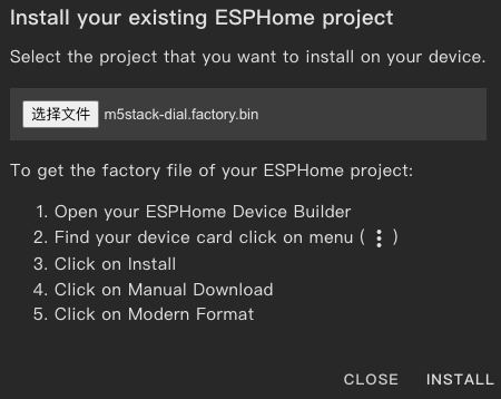
- 在弹出的对话框中,选择
Manual Download。
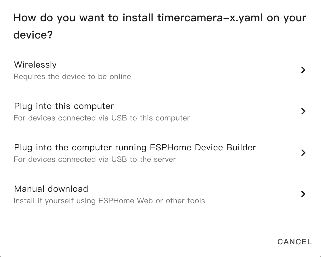
- 等待固件编译完成,然后点击
Download并选择Factory format (Previously Modern)将固件文件保存到本地。
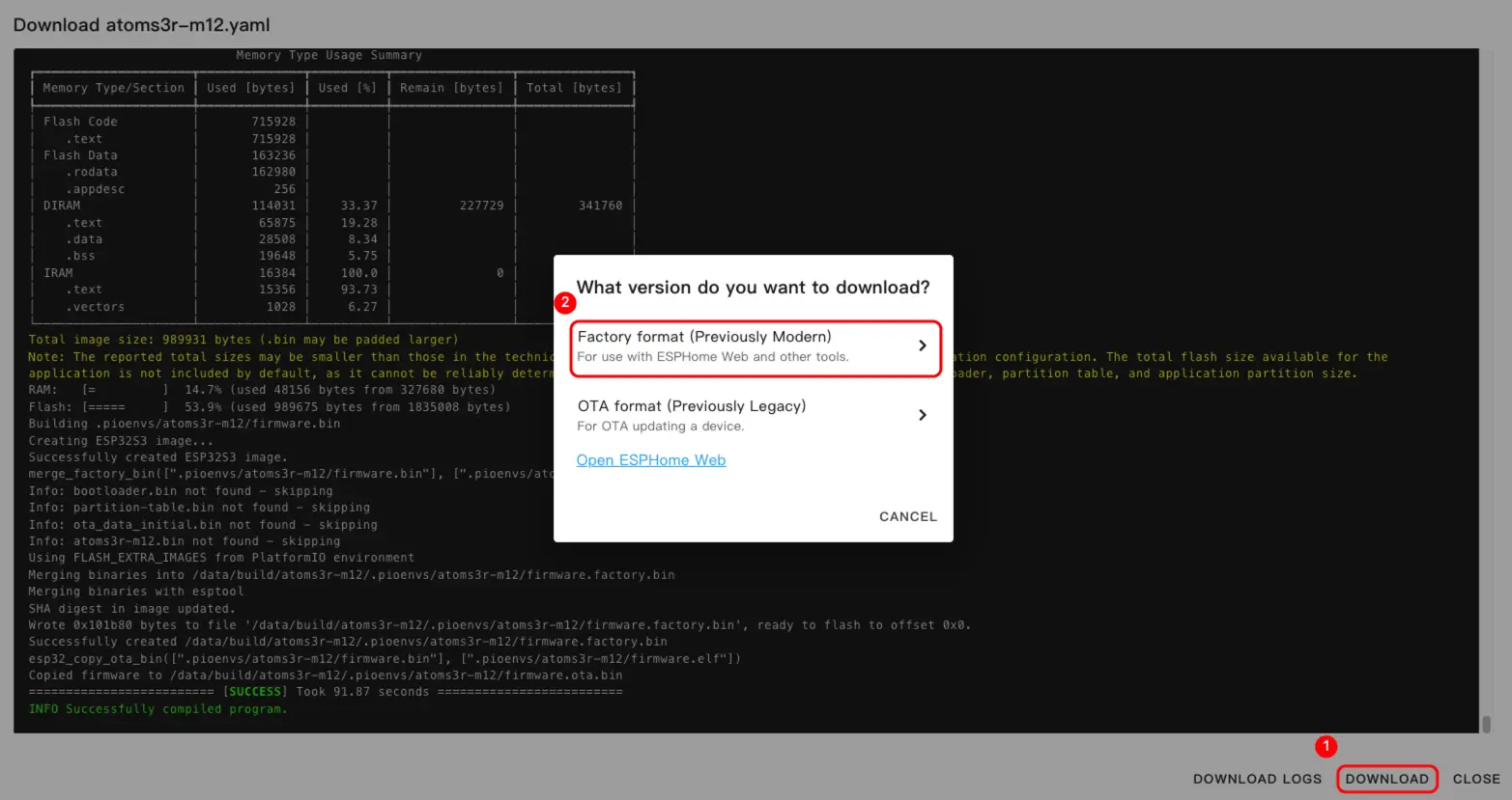
Info
完整的配置示例请参阅 dial-example.yaml。首次编译可能需要一些时间,具体取决于 Home Assistant 主机的性能和网络状况。
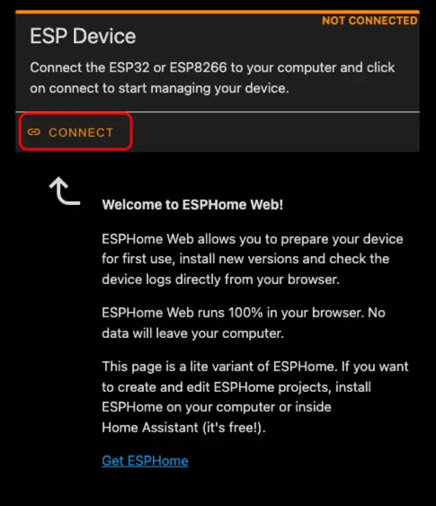
4.2 烧录固件
- 使用 USB Type-C 数据线将 M5Dial 连接到电脑。打开 ESPHome Web 并点击
CONNECT。
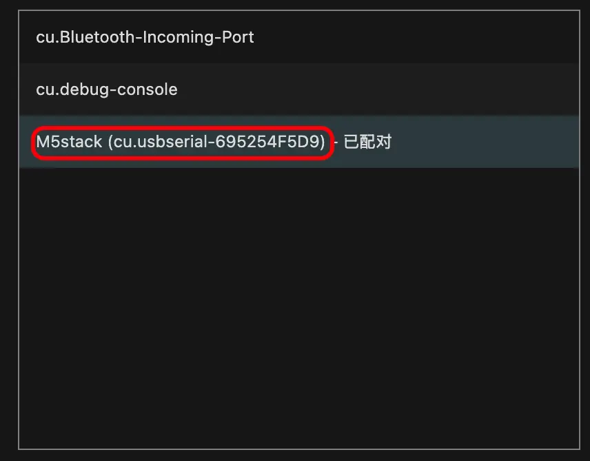
- 在串口选择对话框中,选择正确的端口。
- 点击
INSTALL。
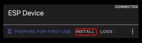
- 选择步骤 3 中下载的固件文件并开始烧录。
Warning
烧录完成后必须重置设备,否则固件可能无法正常启动。
5. 开始在 Home Assistant 中使用
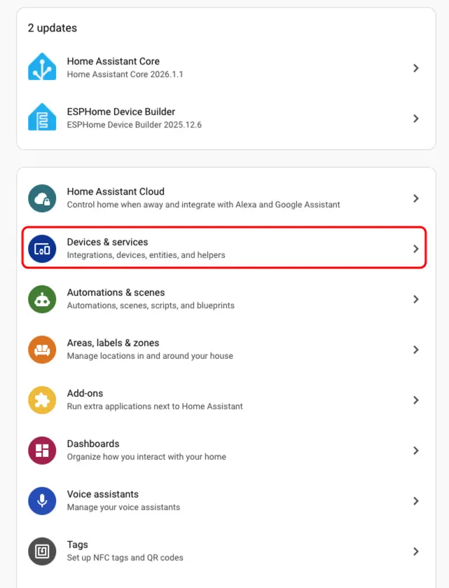
- 在 Home Assistant 中,进入
Settings>Devices & Services打开集成管理页面。
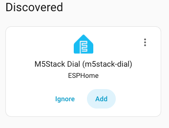
- 在
Discovered区域中找到在线设备,点击CONFIGURE,按照提示完成添加。
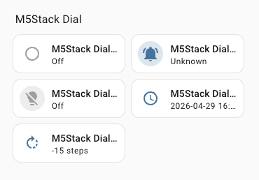
- 添加成功后,设备页面将显示以下实体:
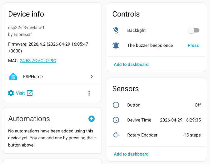
- 最后,将实体添加到仪表盘中,即可实时控制和监控 M5Dial。
Page Tools