

Home Assistant
Media Player
Expansion
Sensor
Dial Home Assistant Integration
This tutorial will use the M5Dial v1.1 development board to integrate into Home Assistant, enabling smart home control through its rotary encoder, RFID reader, and buzzer.

1. Preparation
- Hardware
- 1 x M5Dial v1.1
- 1 x USB Type-C Cable
- 1 x Home Assistant host (server, mini PC, NAS, etc.)
- Software & versions
- ESPHome Device Builder 2026.4.0 or later
2. Create Device
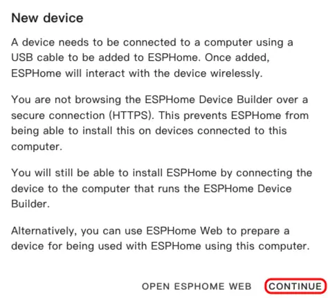
- Open ESPHome Dashboard. If the initial wizard appears, click
CONTINUE.
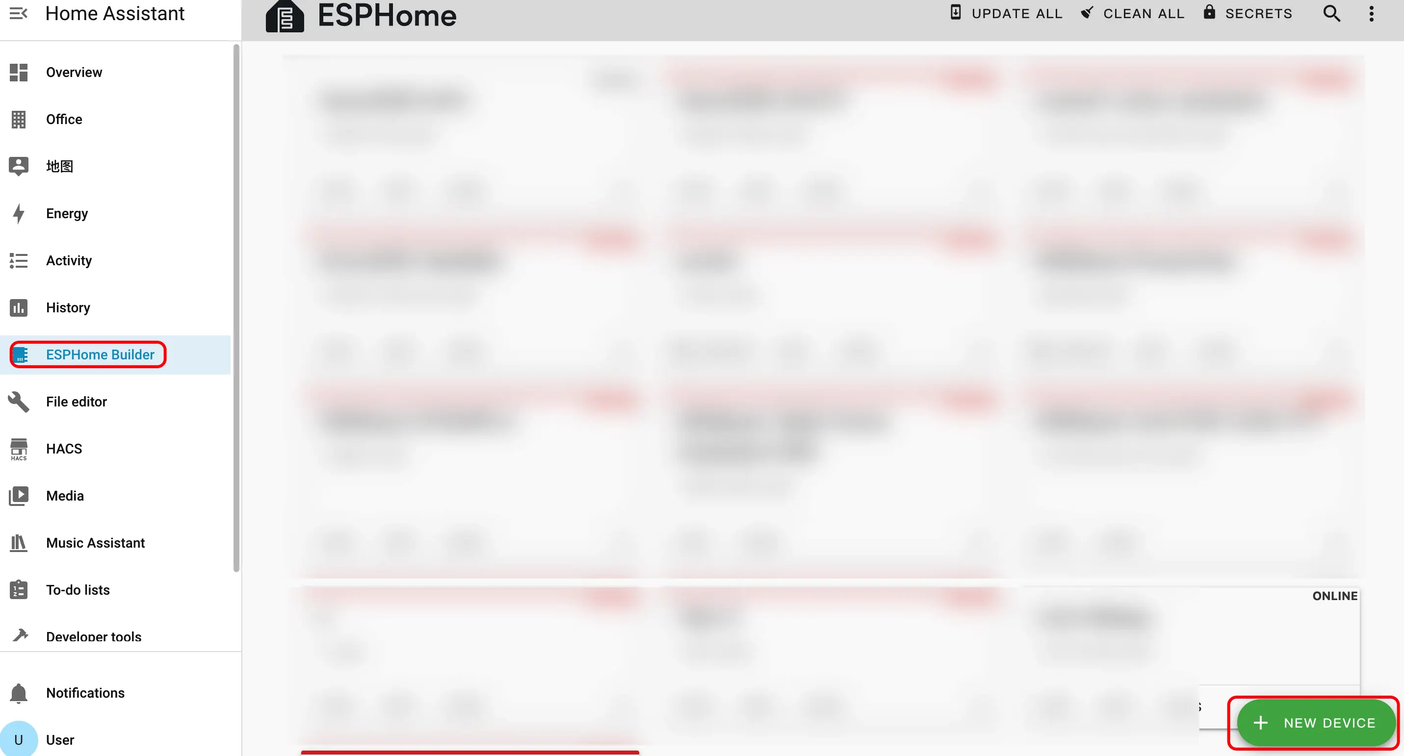
- Click the green + button in the bottom right to create a new device.
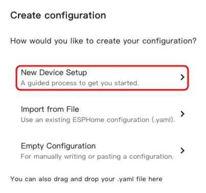
- Click
New Device Setupto enter the device creation wizard.
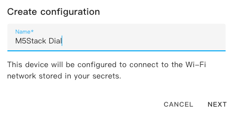
- Enter a device name and click
NEXT.
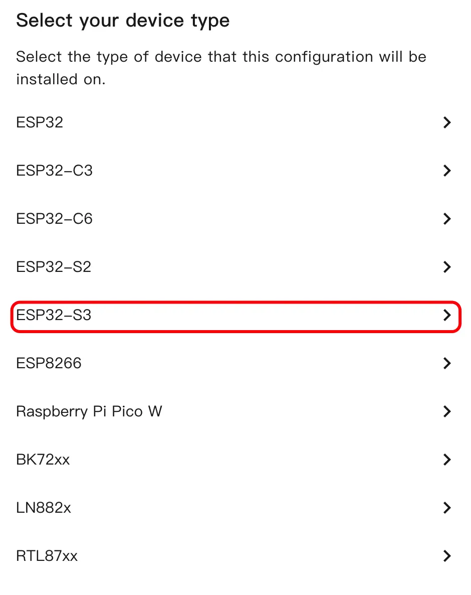
- Select the device type and click
ESP32S3.
- Click
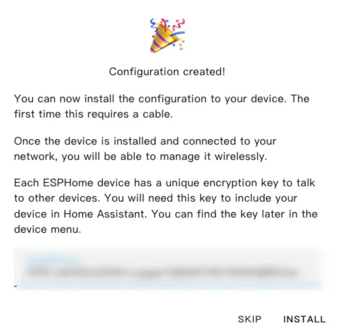
SKIPto skip the encryption key setup.
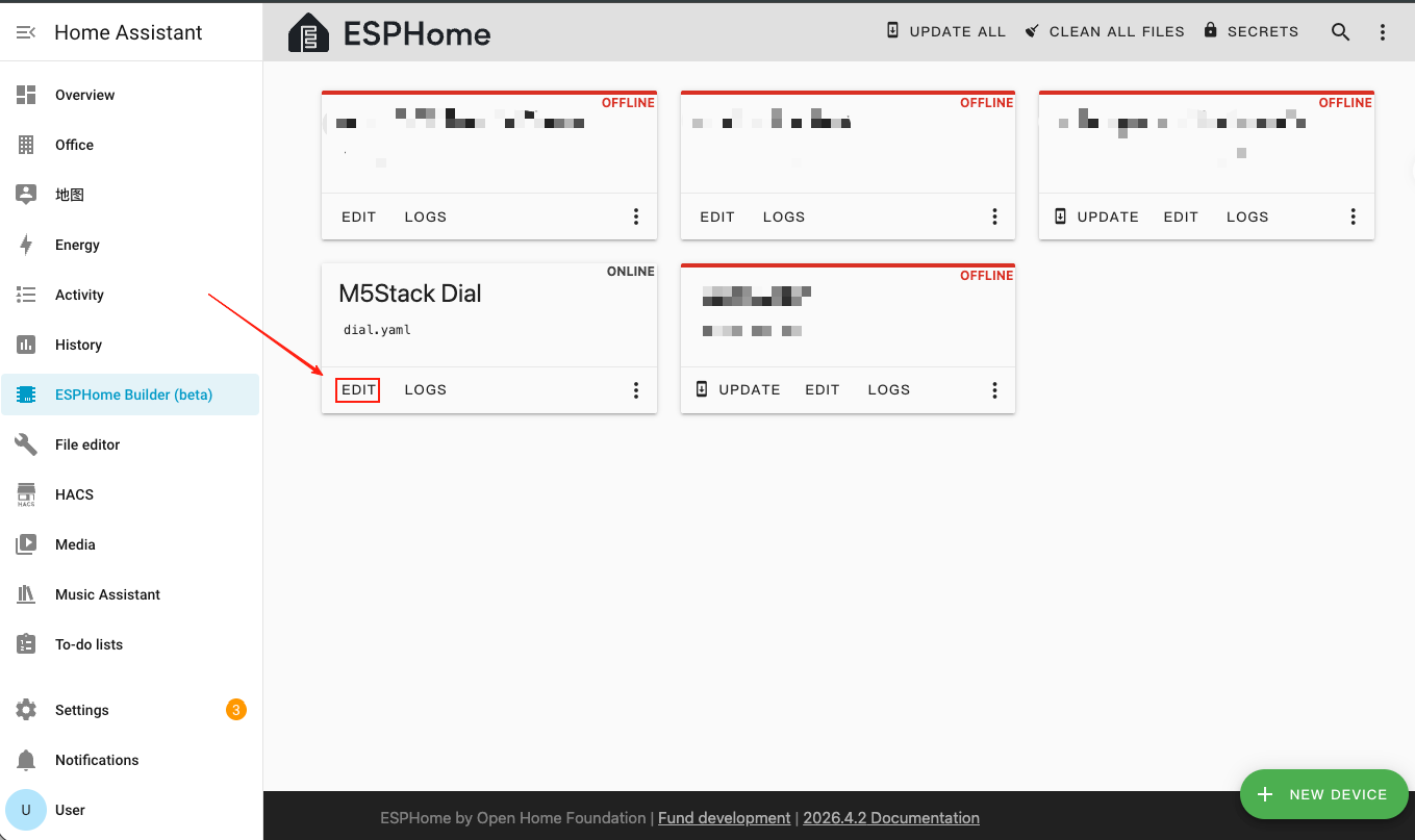
- Click
EDITto open the YAML editor and customize the device configuration.
3. Device Configuration
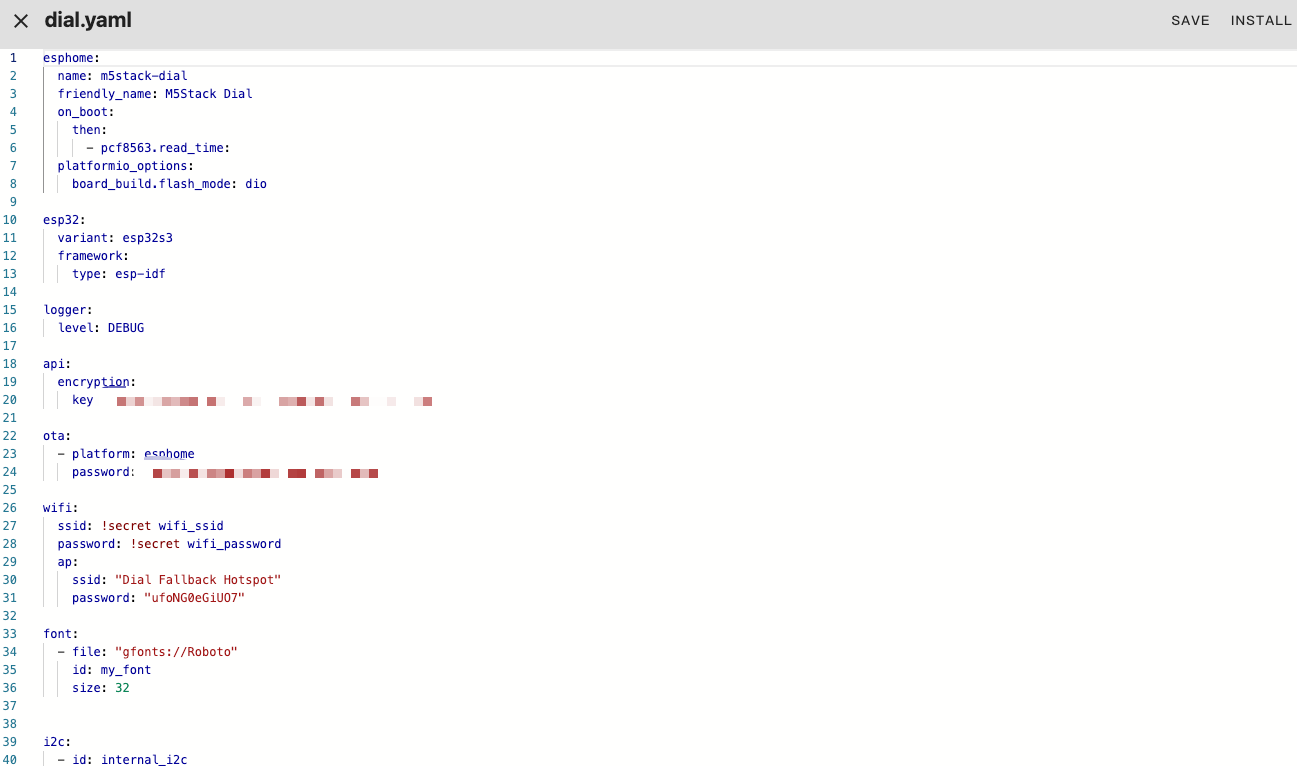
3.1 Basic Configuration
esphome:
  name: m5stack-dial
  friendly_name: M5Stack Dial
  on_boot:
    then:
      - pcf8563.read_time:
  platformio_options:
    board_build.flash_mode: dio

esp32:
  variant: esp32s3
  framework:
    type: esp-idf

logger:
  level: DEBUG

api:
  encryption:
    key: "your_encryption_key"

ota:
  - platform: esphome
    password: "your_ota_password"

wifi:
  ssid: !secret wifi_ssid
  password: !secret wifi_password
  ap:
    ssid: "Dial Fallback Hotspot"
    password: "your_fallback_password"

font:
  - file: "gfonts://Roboto"
    id: my_font
size: 32Main parameter descriptions:
| Parameter | Value | Description |
|---|---|---|
framework.type | esp-idf | Uses ESP-IDF framework for better performance and stability. |
platformio_options | board_build.flash_mode: dio | Flash mode configuration for ESP32-S3. |
on_boot | pcf8563.read_time | Reads RTC time on boot to initialize system clock. |
3.2 I2C & SPI Bus Configuration
i2c:
  - id: internal_i2c
    sda: GPIO11
    scl: GPIO12
    frequency: 400kHz
    scan: true

spi:
  id: spi_bus
  mosi_pin: GPIO5
clk_pin: GPIO6Note
The I2C bus is shared by the PCF8563 RTC (address
0x51), RC522 NFC module (address 0x28), and FT5x06 touch controller (address 0x38). The SPI bus drives the GC9A01A round display.3.3 Display & Touch Screen Configuration
- Add MIPI SPI Display for the 1.28-inch round GC9A01A TFT and FT5x06 Touchscreen for touch input.
display:
  - platform: mipi_spi
    id: round_display
    model: GC9A01A
    cs_pin: GPIO7
    reset_pin: GPIO8
    dc_pin: GPIO4
    invert_colors: true
    data_rate: 40MHz
    update_interval: 1s
    auto_clear_enabled: true
    lambda: |-
      it.print(120, 120, id(my_font), TextAlign::CENTER, "Hello");

touchscreen:
  - platform: ft5x06
    id: touch
    i2c_id: internal_i2c
address: 0x38Main parameter descriptions:
| Parameter | Value | Description |
|---|---|---|
model | GC9A01A | MIPI SPI display controller for the round screen. |
cs_pin | GPIO7 | SPI chip select pin. |
reset_pin | GPIO8 | Display reset pin. |
dc_pin | GPIO4 | Display data/command pin. |
invert_colors | true | Required for GC9A01A correct color display. |
touchscreen.address | 0x38 | I2C address of the FT5x06 touch controller. |
3.4 Backlight Configuration
- Add Monochromatic Light to control the display backlight via GPIO9.
output:
  - platform: ledc
    pin: GPIO9
    id: backlight_output
    frequency: 1000Hz

light:
  - platform: monochromatic
    name: "Backlight"
    output: backlight_output
    id: display_backlight
default_transition_length: 0s3.5 Rotary Encoder & Button Configuration
- Add Rotary Encoder Sensor to read the knob position and GPIO Binary Sensor for the under-screen button.
sensor:
  - platform: rotary_encoder
    id: encoder
    name: "Rotary Encoder"
    pin_a:
      number: GPIO40
      mode: INPUT_PULLUP
    pin_b:
      number: GPIO41
      mode: INPUT_PULLUP
    resolution: 4
    min_value: -32768
    max_value: 32767
    publish_initial_value: true

binary_sensor:
  - platform: gpio
    name: Button
    id: front_button
    pin:
      number: GPIO42
      inverted: true
      mode:
        input: true
pullup: trueMain parameter descriptions:
| Parameter | Value | Description |
|---|---|---|
encoder.pin_a | GPIO40 (INPUT_PULLUP) | Encoder signal pin A. |
encoder.pin_b | GPIO41 (INPUT_PULLUP) | Encoder signal pin B. |
encoder.resolution | 4 | Encoder resolution mode (counts 4 edges per pulse). |
front_button.pin | GPIO42 (inverted) | Under-screen button, pulled high when open, low when pressed. |
3.6 NFC Reader (RC522) Configuration
- Add RC522 I2C component to detect NFC/RFID tags via the built-in WS1850S module.
rc522_i2c:
  - id: nfc_reader
    i2c_id: internal_i2c
    address: 0x28
    update_interval: 500ms
    on_tag:
      - lambda: |-
          ESP_LOGD("rfid", "Card detected: %s", x.c_str());
    on_tag_removed:
      - lambda: |-
ESP_LOGD("rfid", "Card removed: %s", x.c_str());Main parameter descriptions:
| Parameter | Value | Description |
|---|---|---|
address | 0x28 | I2C address of the WS1850S/RC522 NFC module. |
update_interval | 500ms | Polling interval for tag detection. |
on_tag | — | Triggered when an NFC tag is detected. |
on_tag_removed | — | Triggered when an NFC tag is removed. |
3.7 Buzzer (RTTTL) Configuration
- Add RTTTL component to play melodies through the onboard buzzer on GPIO3.
output:
  - platform: ledc
    pin: GPIO3
    id: buzzer
    frequency: 4000Hz

rtttl:
  output: buzzer
  id: rtttl_player
  gain: 0.6

button:
  - platform: template
    name: "The buzzer beeps once"
    id: buzzer_button
    icon: mdi:bell-ring
    on_press:
      - rtttl.play:
          id: rtttl_player
rtttl: "beep:d=4,o=5,b=180:16e,16e"3.8 RTC Time Configuration
- Add PCF8563 Time component to use the onboard RTC as the time source.
time:
  - platform: pcf8563
    id: rtctime
    i2c_id: internal_i2c
    address: 0x51
    update_interval: never

text_sensor:
  - platform: template
    name: "Device Time"
    id: current_time_str
    icon: mdi:clock-outline
    update_interval: 10s
    lambda: |-
      auto t = id(rtctime).now();
      if (!t.is_valid()) return {"--:--:--"};
      char buf[20];
      snprintf(buf, sizeof(buf), "%04d-%02d-%02d %02d:%02d:%02d",
               t.year, t.month, t.day_of_month,
               t.hour, t.minute, t.second);
return {buf};Main parameter descriptions:
| Parameter | Value | Description |
|---|---|---|
address | 0x51 | I2C address of the PCF8563 / BM8563 RTC chip. |
update_interval | never | Disables automatic RTC sync (system time is loaded at boot). |
4. Build and Flash Firmware
4.1 Build firmware
- After editing the YAML configuration, click
SAVEin the top right, then clickINSTALL.
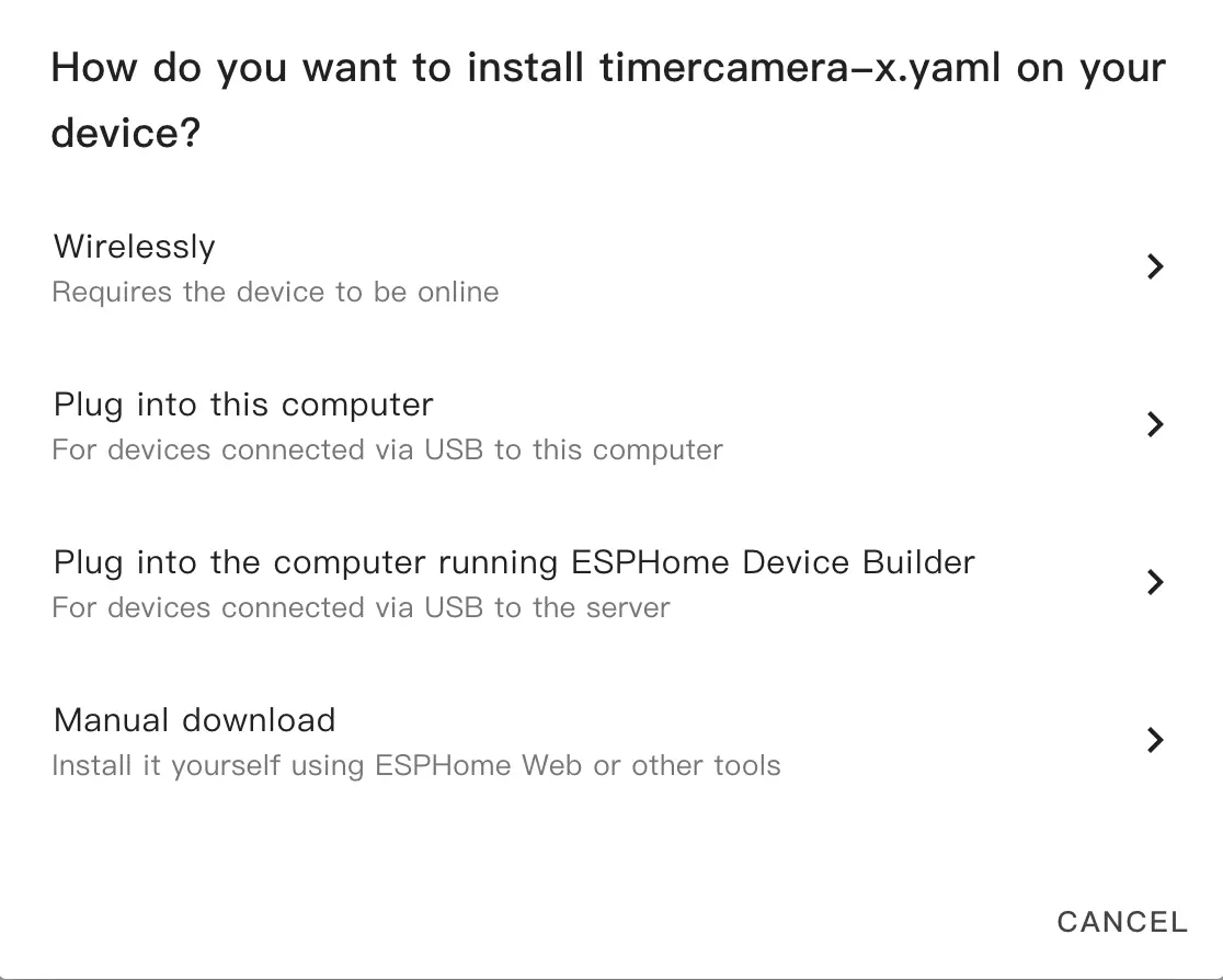
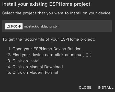
- In the popup dialog, select
Manual Download.
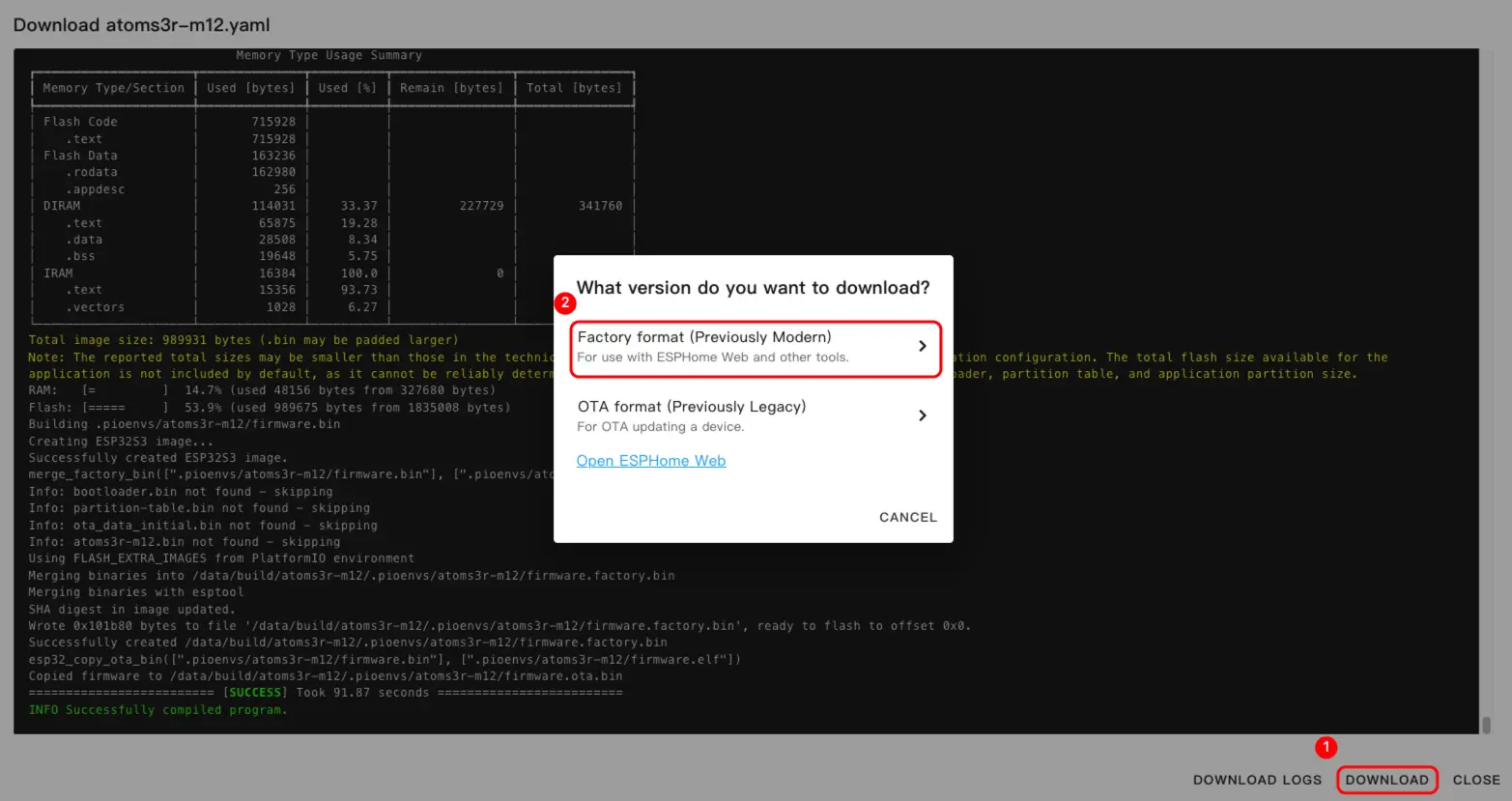
- Wait for the firmware to compile, then click
Downloadand chooseFactory format (Previously Modern)to save the firmware file locally.
Info
For a complete example configuration, see dial-example.yaml. The first build may take some time depending on the performance of your Home Assistant host and network conditions.
4.2 Flash firmware
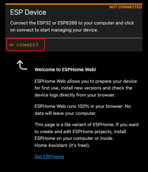
- Connect M5Dial to your computer using a USB Type-C cable. Open ESPHome Web and click
CONNECT.
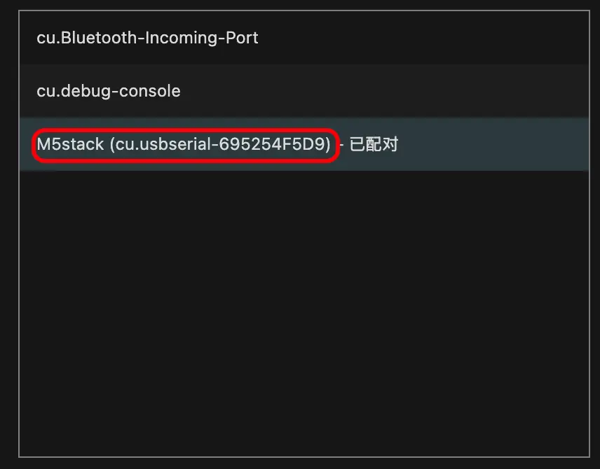
- In the serial port selection dialog, select the correct port.
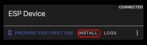
- Click
INSTALL.
- Select the firmware file downloaded in step 3 and start flashing.
Warning
After flashing is complete, you must reset the device; otherwise the firmware may not start correctly.
5. Start Using in Home Assistant
- In Home Assistant, go to
Settings>Devices & Servicesto open the integration management page.
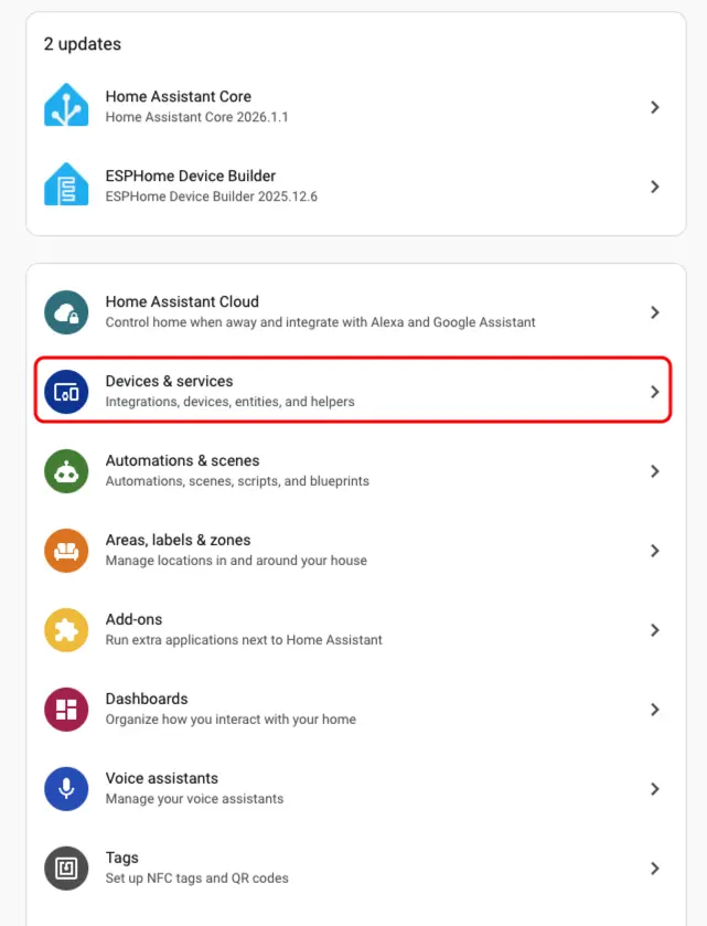
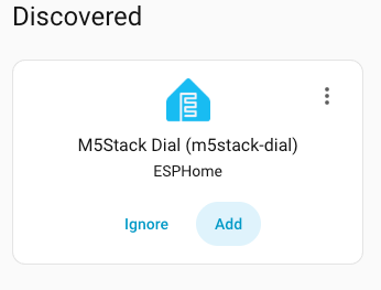
- Find the online device in the
Discoveredarea, clickCONFIGURE, and follow the prompts to complete the addition.
- After successful addition, the device page will display the following entities:
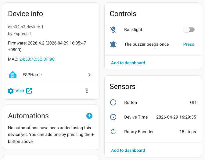
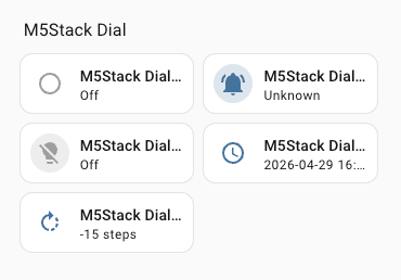
- Finally, add the entities to the dashboard to control and monitor the M5Dial in real time.
Page Tools