


Home Assistant
Media Player
Expansion
Sensor
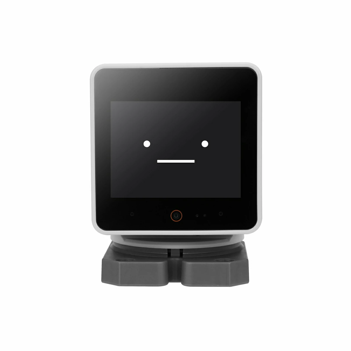
StackChan Home Assistant Integration
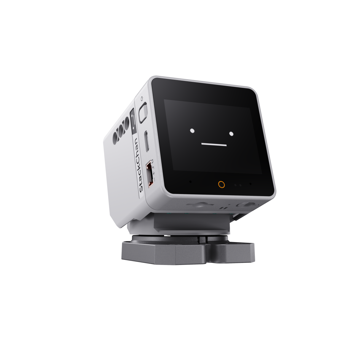
StackChan is a super cute AI desktop robot created jointly by M5Stack and the user community. It is powered by the M5Stack flagship IoT development kit CoreS3 with an ESP32-S3 main controller, a 240 MHz dual-core processor, 16MB flash, and 8MB PSRAM. It supports Wi-Fi and BLE. The host also includes a 2.0-inch tough glass capacitive touchscreen, 0.3 MP camera, proximity sensor, nine-axis motion sensor (accelerometer + gyroscope + geomagnetic), microSD card slot, 1W speaker, dual microphones, and power/reset buttons.
This article introduces how to integrate a variety of StackChan peripherals. If you need a ready-to-use voice assistant, please refer to:
If you need to download pre-built firmware yourself, check the GitHub Release.
Requirements
- A Home Assistant host.
- Install and enable ESPHome Builder in Home Assistant.
Quick Start
Click the button below to flash the firmware in one click. Follow the on-screen instructions to complete the setup and quickly experience StackChan integrated with Home Assistant. For details on one-click flashing and subsequent configuration, please refer to the tutorial.
2026.3 Initial firmware
Create the Device
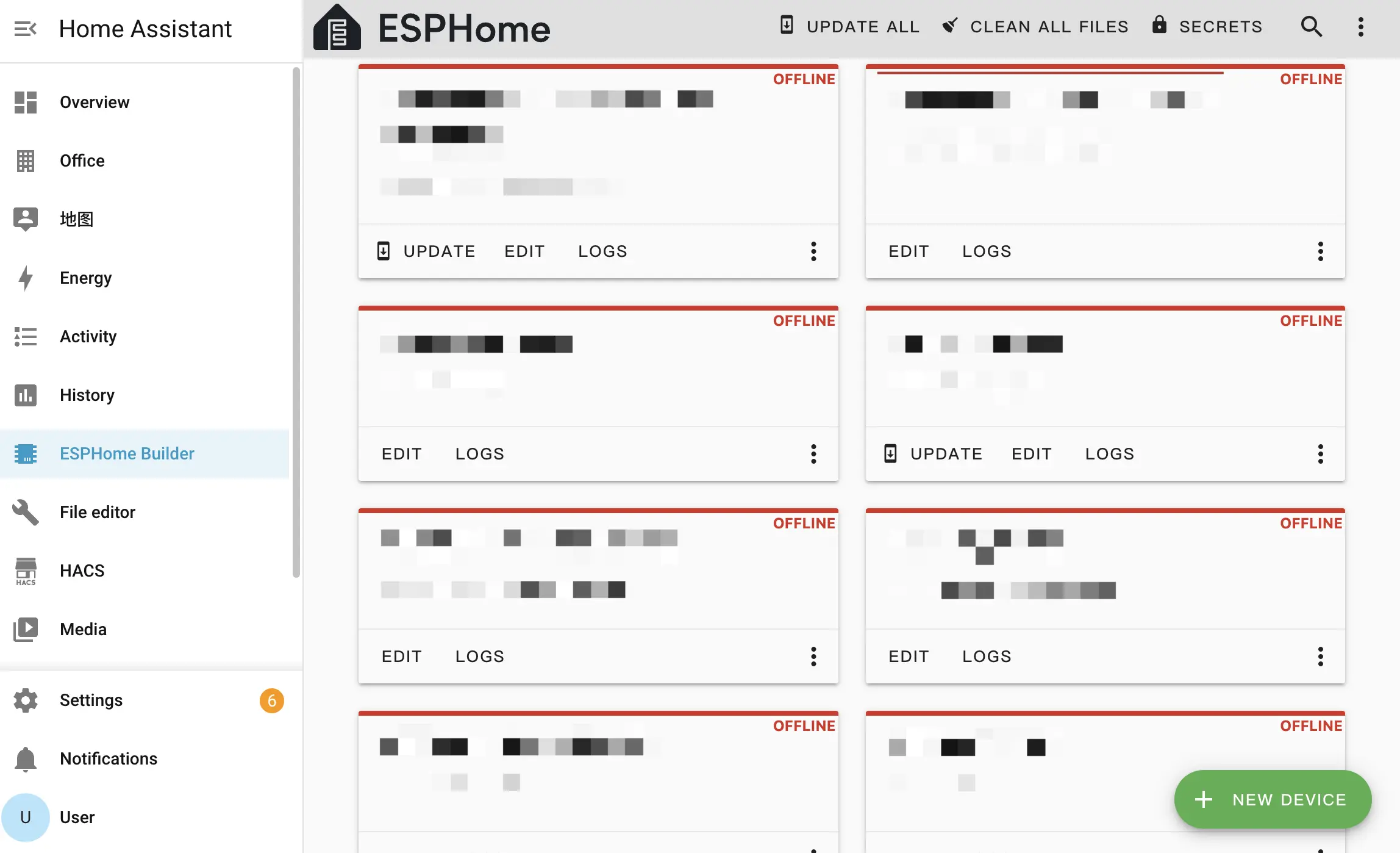
- Open ESPHome Builder in Home Assistant and create a configuration.
- Click the
NEW DEVICEbutton in the bottom right.
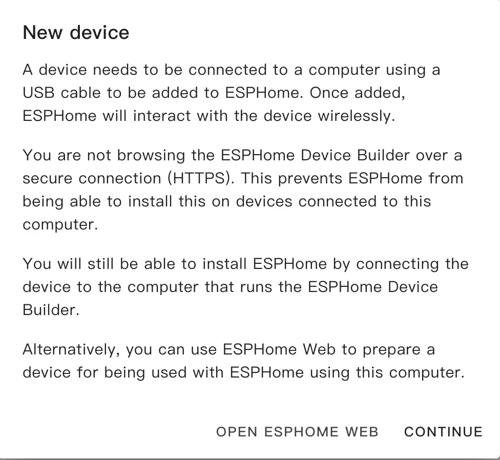
- Click
CONTINUEin the popup.
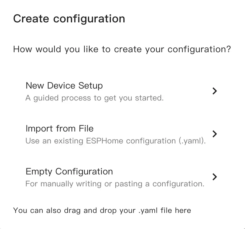
- Select
New Device Setup.
- Enter a name.
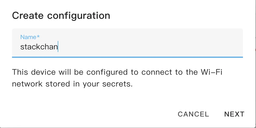
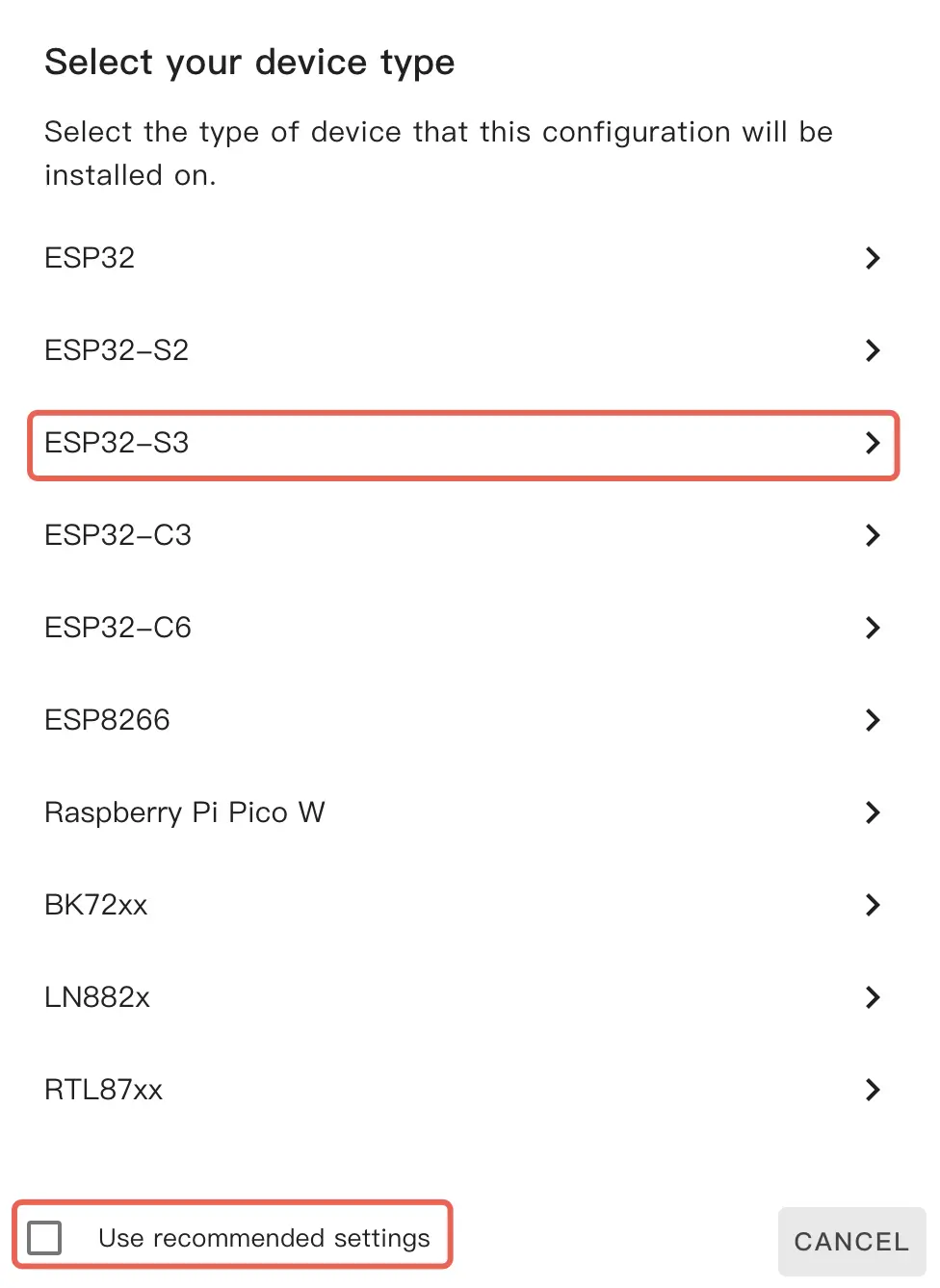
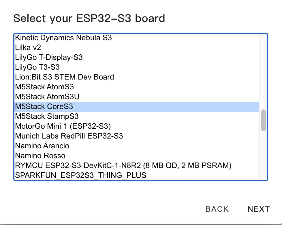
- Select device type. First uncheck
Use recommended settings, then clickESP32-S3and chooseM5Stack CoreS3from the list.
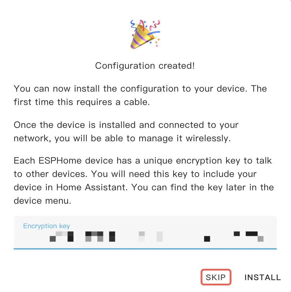
- Copy the API backup, then click
SKIP.
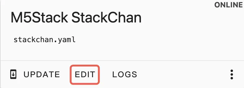
- Click
EDITon the newly generated configuration card.
- Add the package section at the end of the file.
packages:
  remote_package_files:
    url: https://github.com/m5stack/esphome-yaml
    files: [examples/kit/stackchan-bsp.factory.yaml]
    ref: main
    refresh: 0s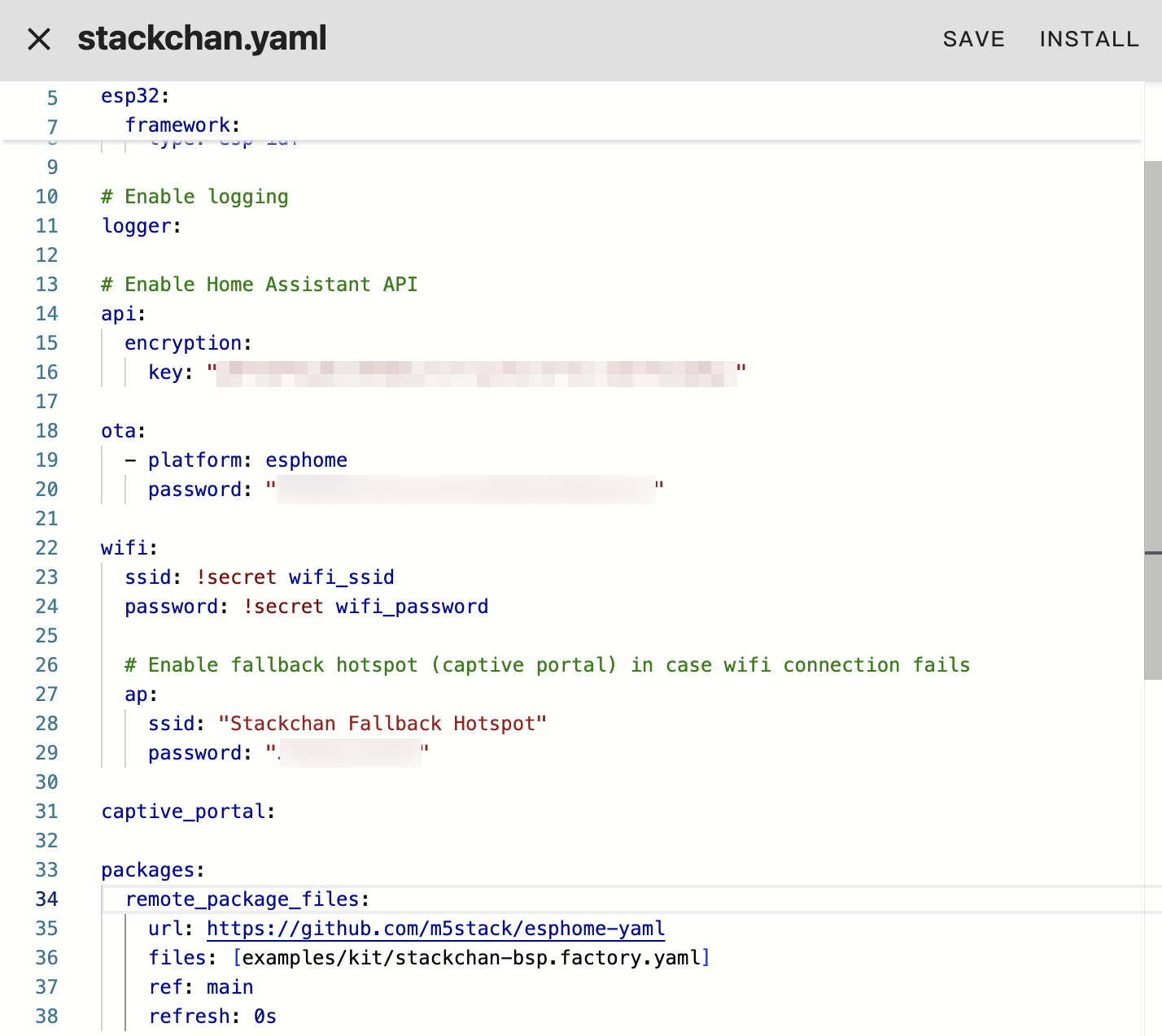
- Save the file and compile.
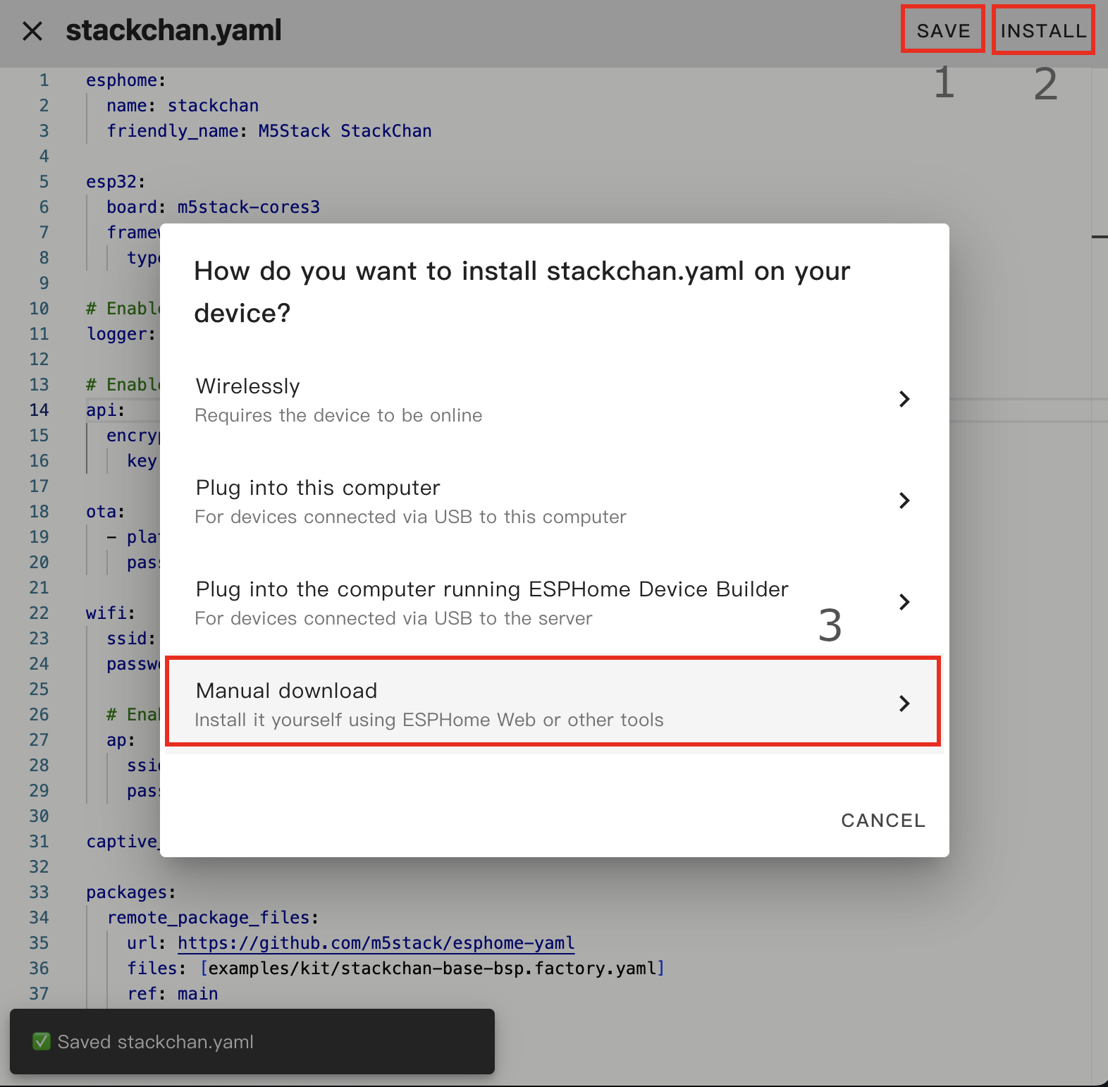
- Click
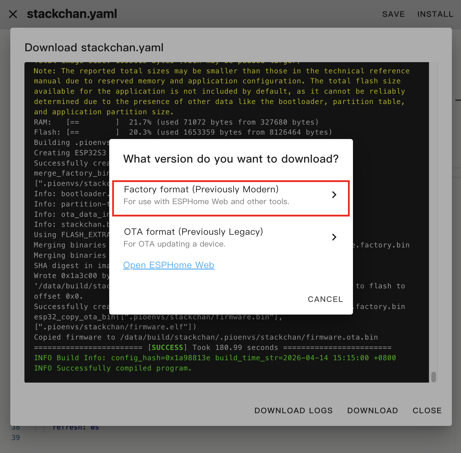
SAVEand thenINSTALLin the top right, chooseManual Downloadwhen prompted.
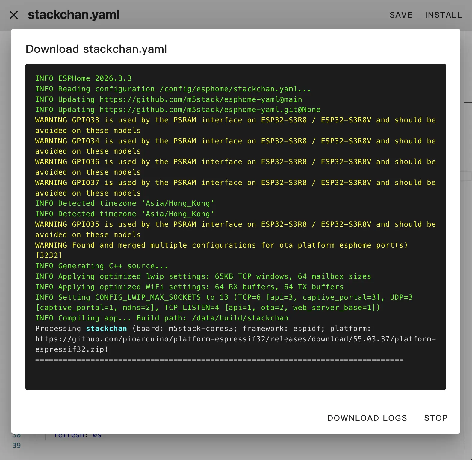
Download and Flash the Firmware
- After compilation completes, choose
Factory Formatand download the firmware.
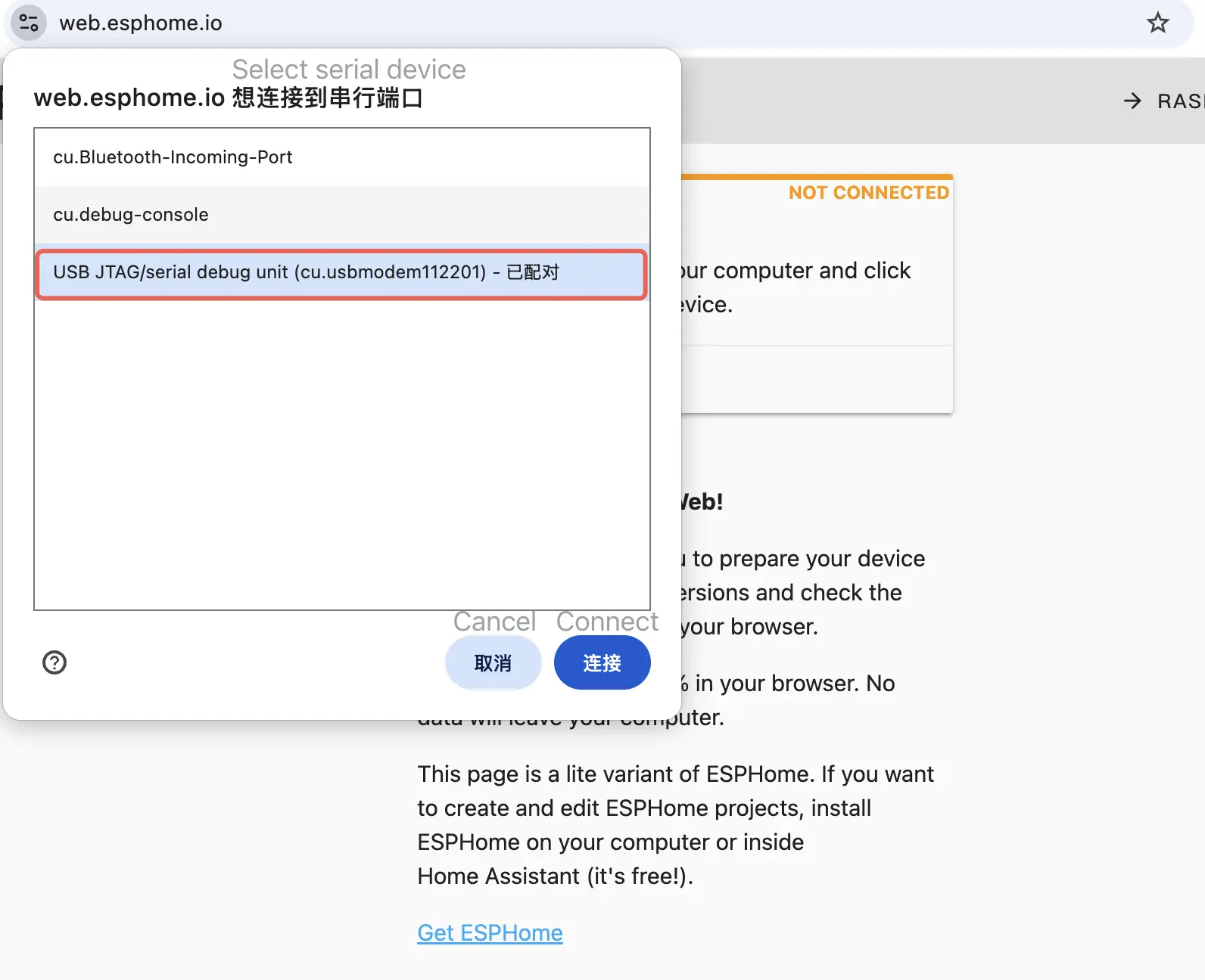
- Flash the firmware using the web tool:
Connect StackChan to the computer via USB-C, hold the reset button until the green LED lights up, then release it to enter download mode.
Open ESPHome Web in the browser and click
CONNECTto connect the device.
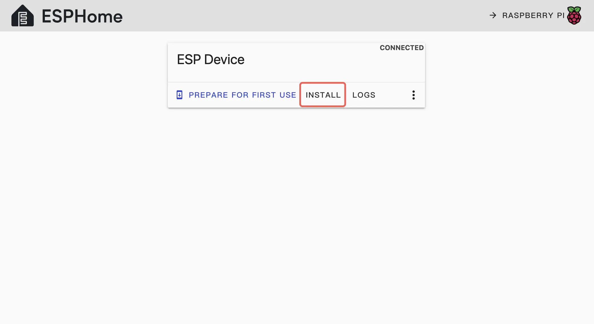
- Click
INSTALL, select the downloaded firmware, and clickINSTALLagain to flash it.
- Click
INSTALLagain to write the firmware to the device.
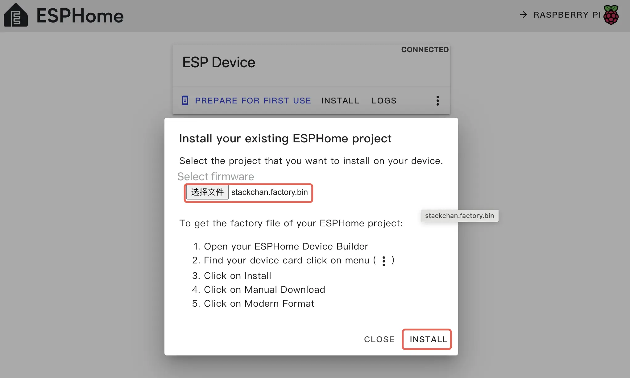
Wait for the flash to complete.
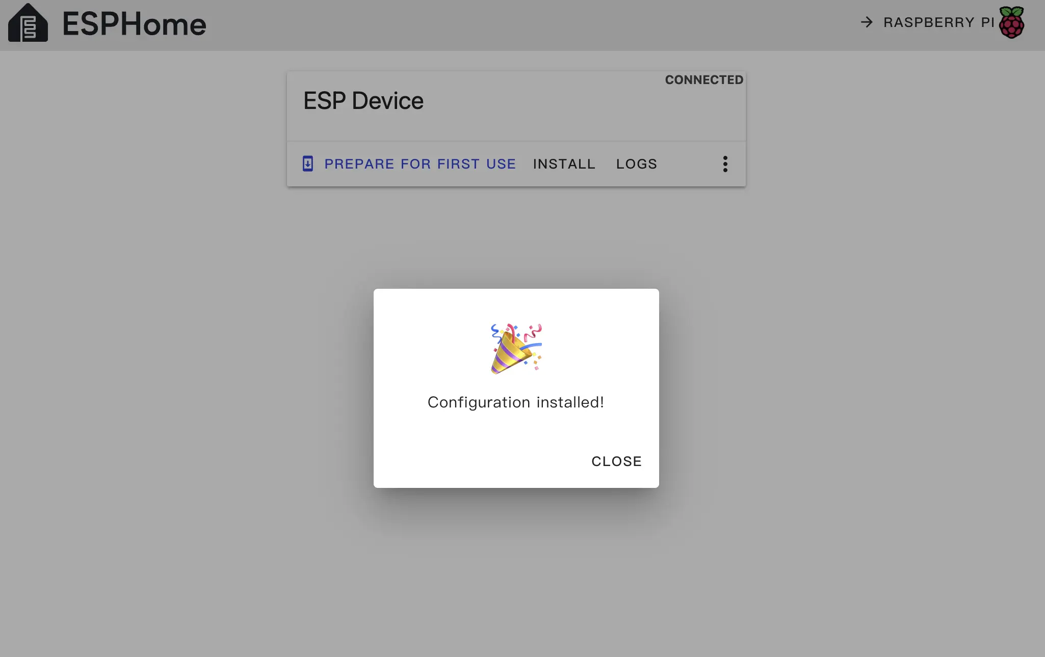
- After flashing, press the RESET button on StackChan to reboot.
Getting Started
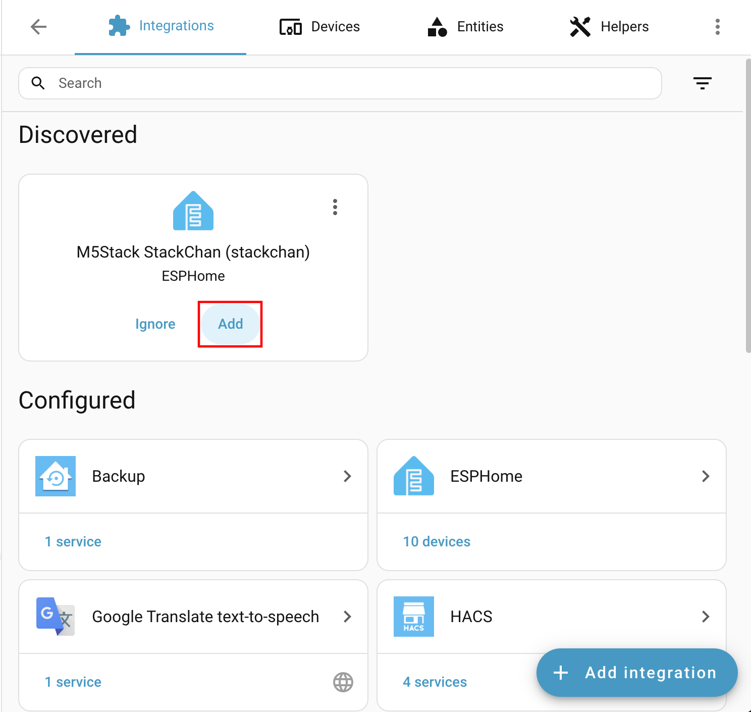
After flashing and rebooting, the device will automatically connect to Wi-Fi. Home Assistant on the same LAN should prompt a new device discovery. Check
Settings -> Devices & services.When the device is found:
- Click
Addon the discovery page.
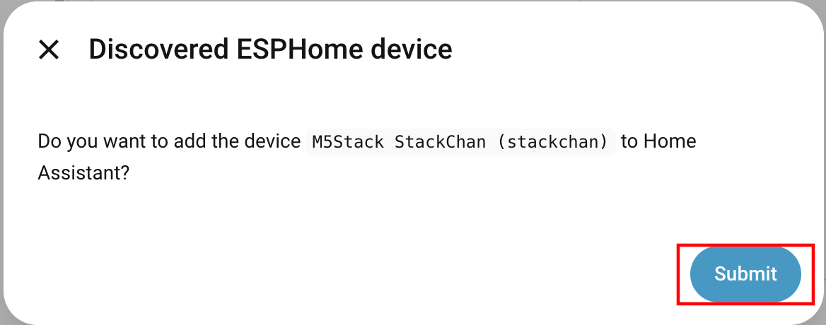
- Confirm the dialog by selecting
Submit.
- If you used an API key for encryption, enter it during validation; otherwise continue with the normal setup.
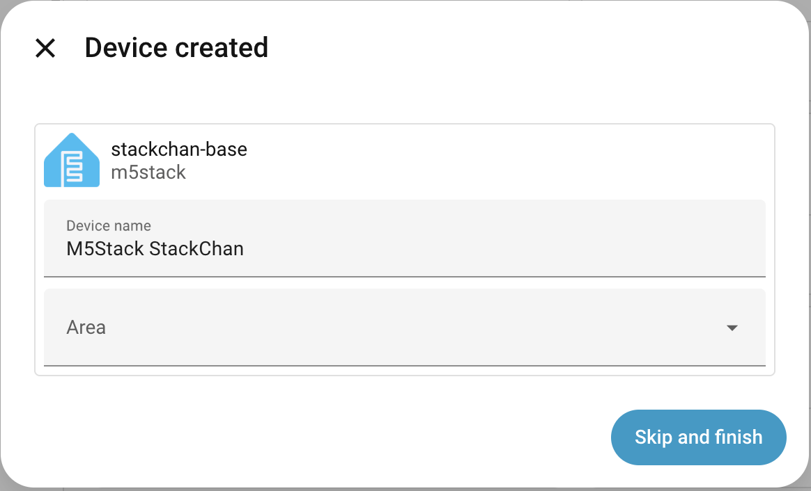
After adding, the device will appear under the ESPHome integration along with its entities and dashboard.
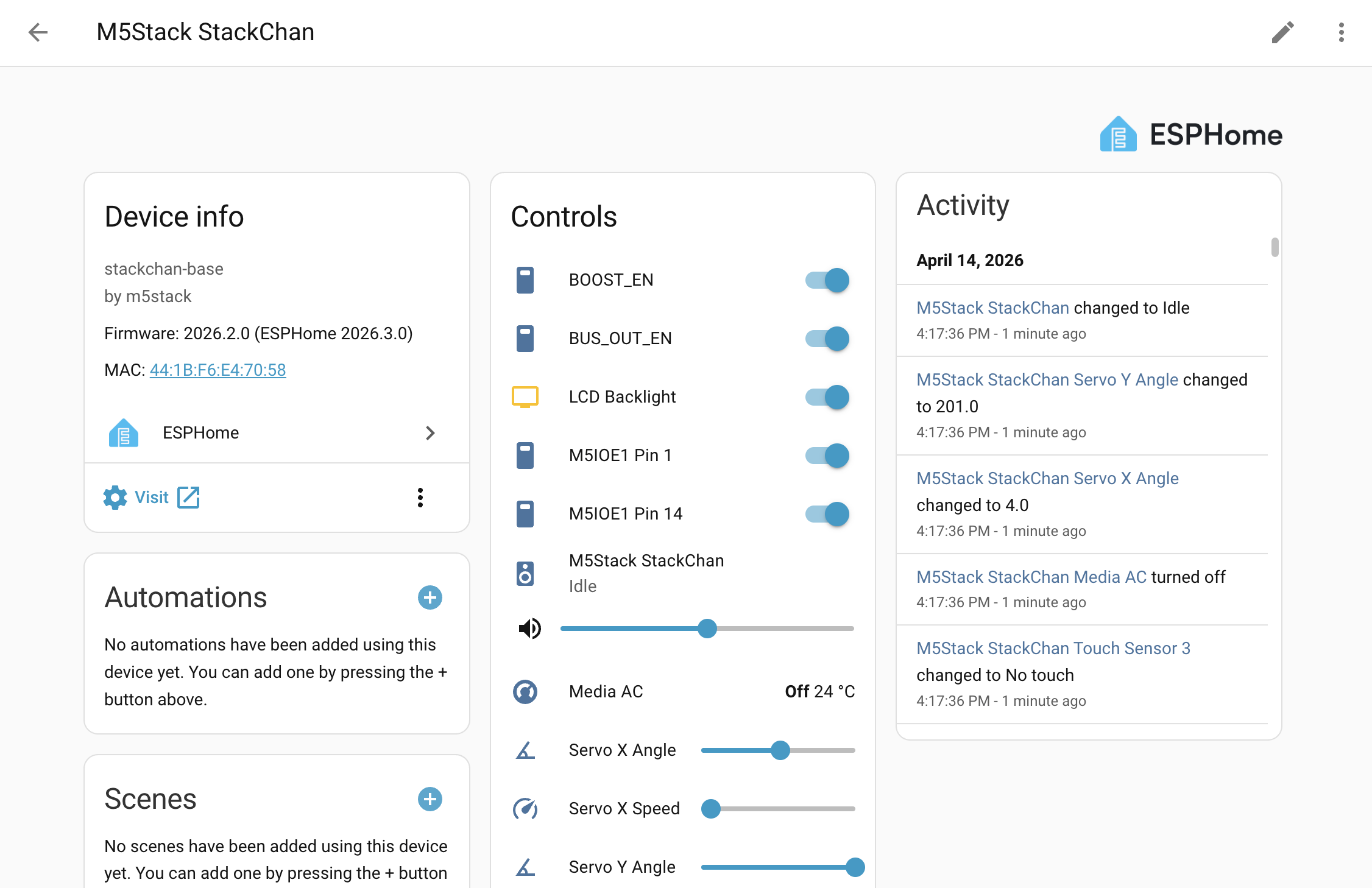
Peripheral Overview
This section describes the various StackChan components, mainly separated into CoreS3 host, Power Board, and Touch Board IC devices.
Main pin configuration:
i2s_audio:
  id: i2s_audio_bus
  i2s_lrclk_pin: GPIO33
  i2s_bclk_pin: GPIO34
  i2s_mclk_pin:
    number: GPIO0
    ignore_strapping_warning: true

i2c:
  - id: bsp_bus
    sda: GPIO12
    scl: GPIO11
    frequency: 100kHz
    scan: true

spi:
  - id: spi_bus
    clk_pin: GPIO36
    mosi_pin: GPIO37

uart:
  tx_pin: GPIO6
  rx_pin: GPIO7
baud_rate: 1000000PMIC AXP2101
This component requires I2C and uses the output component to configure LDOs:
axp2101:
  id: axp2101_pmu
  i2c_id: bsp_bus

output:
  - platform: axp2101
    type: range
    channel: DLDO1
    id: lcd_backlight_output
    min_voltage: 2600
    max_voltage: 3300

  - platform: axp2101
    channel: ALDO1
    voltage: 1800
...IO Expander AW9523B
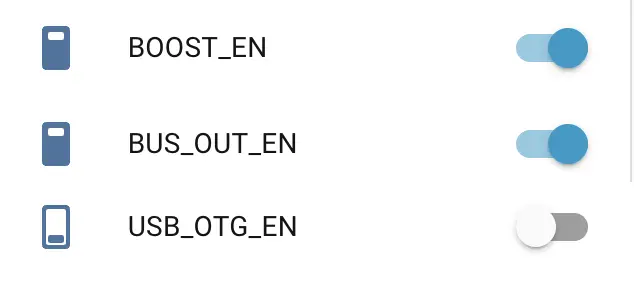
This component requires I2C and supports Pin Schema. It is mainly used for reset/power control. All switches used for reset signals are marked internal: true and are not exposed to the Home Assistant frontend. At the same time, BOOST_EN, BUS_OUT_EN, and USB_OTG_EN control power direction. See the power management example. When using it, enable BOOST_EN first; then BUS_OUT_EN and USB_OTG_EN can take effect.
aw9523b:
  id: aw9523b_hub
  i2c_id: bsp_bus
  p0_drive_mode: PUSH_PULL

switch:
  - platform: gpio
    name: "AW RST P0_2"
    pin:
      aw9523b_id: aw9523b_hub
      number: 2
    internal: true
    restore_mode: RESTORE_DEFAULT_ON
    ...
Audio ADC ES7210
This component requires I2C. If using the voice assistant, sample_rate must be 16000.
audio_adc:
  - platform: es7210
    id: es7210_adc
    i2c_id: bsp_bus
    bits_per_sample: 16bit
    sample_rate: 16000
mic_gain: 36Microphone
This component requires I2S support. The microphone component can be used with the voice assistant and will not display in the HA frontend.
microphone:
  - platform: i2s_audio
    id: i2s_mic
    i2s_din_pin: GPIO14
    adc_type: external
    sample_rate: 16000
    bits_per_sample: 16bit
i2s_audio_id: i2s_audio_busAudio Amplifier AW88298
audio_dac:
  - platform: aw88298
    id: aw88298_dac
    i2c_id: bsp_bus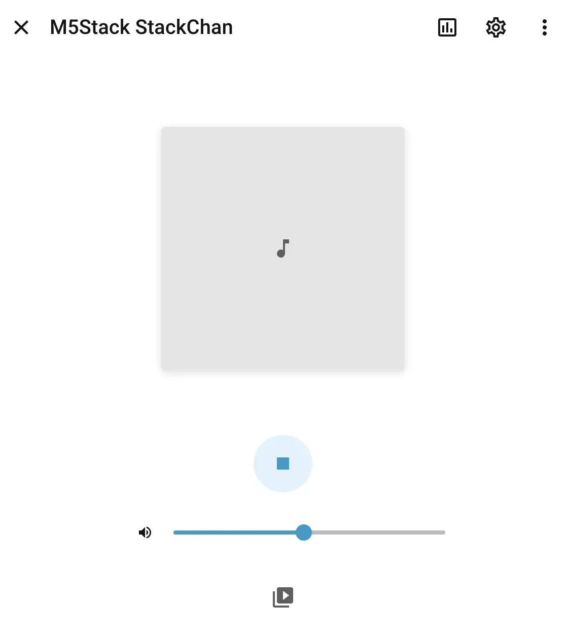
sample_rate: 48000Speaker / Media Player
This component requires I2S. The media player can be used in the Home Assistant frontend to play audio.
speaker:
  - platform: i2s_audio
    i2s_audio_id: i2s_audio_bus
    id: i2s_speaker
    dac_type: external
    i2s_dout_pin: GPIO13
    audio_dac: aw88298_dac

media_player:
  - platform: speaker
    name: None
    id: va_media_player
    volume_min: 0.5
    volume_max: 0.8
    announcement_pipeline:
      speaker: i2s_speaker
      format: FLAC
      sample_rate: 48000
      num_channels: 1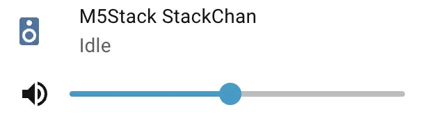
LCD ILI9342C
This component requires SPI. The maximum data_rate can only be 40MHz. Set invert_colors to true to match the correct RGB colors.
display:
  - platform: mipi_spi
    model: M5CORE
    dc_pin: GPIO35
    reset_pin:
      aw9523b_id: aw9523b_hub
      number: 9
    cs_pin:
      number: GPIO3
      ignore_strapping_warning: true
    data_rate: 40MHz
    invert_colors: true
    id: m5cores3_lcd
    show_test_card: true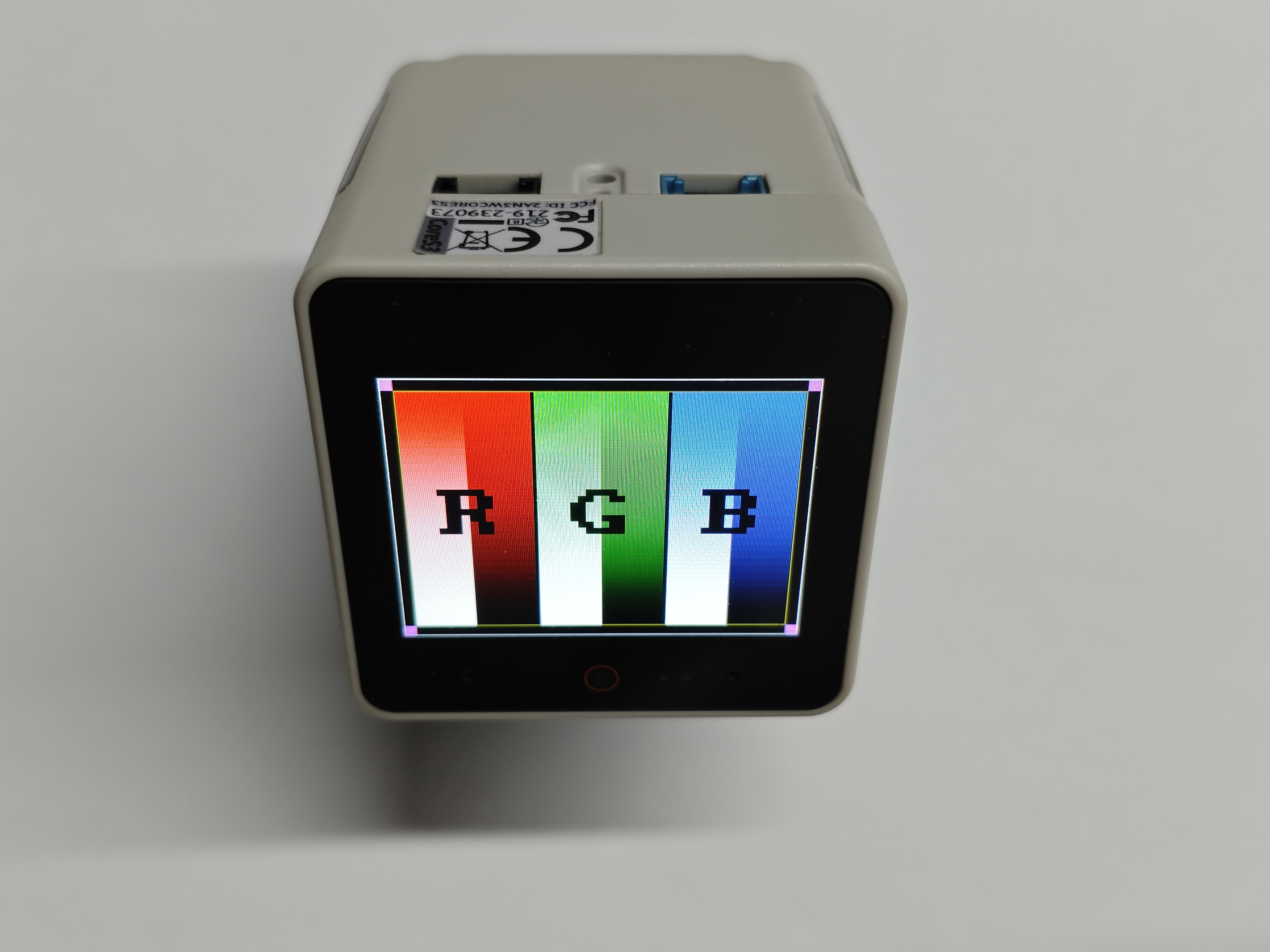
Camera GC0308
This component requires I2C. Enabling it allows real-time video stream data to appear in the Home Assistant frontend.
esp32_camera:
  name: "Camera"
  i2c_id: bsp_bus
  vsync_pin:
    number: GPIO46
    ignore_strapping_warning: true
  href_pin: GPIO38
  external_clock:
    pin: GPIO2
    frequency: 20MHz
  pixel_clock_pin:
    number: GPIO45
    ignore_strapping_warning: true
  data_pins: [GPIO39, GPIO40, GPIO41, GPIO42, GPIO15, GPIO16, GPIO48, GPIO47] # D0-D7
  max_framerate: 15.0 fps
  resolution: 320x240
  frame_buffer_count: 1
  pixel_format: RGB565
  jpeg_quality: 6
  agc_mode: manual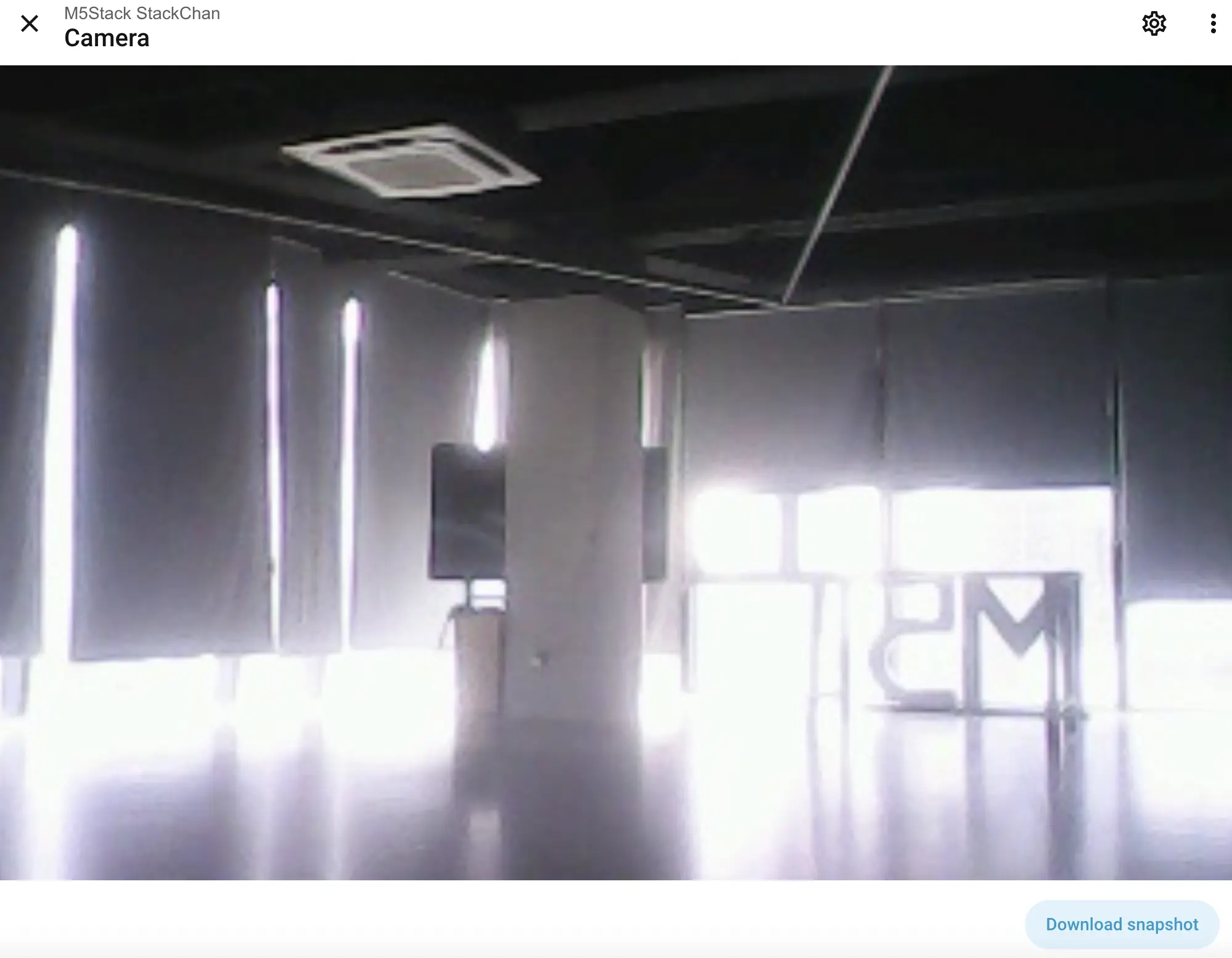
RTC BM8563
This component requires I2C. It can synchronize time with the internet or Home Assistant host:
esphome:
  ...
  on_boot:
    then:
      # read the RTC time once when the system boots
      bm8563.read_time:

time:
  - platform: bm8563
    i2c_id: bsp_bus
    # repeated synchronization is not necessary unless the external RTC
    # is much more accurate than the internal clock
    update_interval: never
  - platform: homeassistant
    # instead try to synchronize via network repeatedly ...
    on_time_sync:
      then:
        # ... and update the RTC when the synchronization was successful
        bm8563.write_time:
The above data is only visible in serial logs.
Proximity Sensor LTR-553ALS-WA
This component requires I2C and can provide ambient light/proximity data:
sensor:
  - platform: ltr_als_ps
    address: 0x23
    i2c_id: bsp_bus
    update_interval: 10s
    type: ALS_PS
    ambient_light:
      name: "Ambient light"
    glass_attenuation_factor: 2.5
    auto_mode: true
    ps_cooldown: 5 s
    ps_high_threshold: 500
    # on_ps_high_threshold:
    #   then:
    #     - .... # do something - light up the screen for example
    ps_counts: "Proximity counts"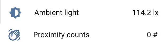
BMI270 6-axis Motion Sensor (WIP)
BMM150 3-axis Magnetometer (WIP)
M5IOE1 Multi-function IO Expander
This component requires I2C.
m5ioe1:
  id: m5ioe1_hub
  i2c_id: bsp_bus
  reset: true

switch:
  - platform: gpio
    name: "M5IOE1 Pin 1"
    pin:
      m5ioe1_id: m5ioe1_hub
      number: 0
      mode:
        output: true
        pullup: true
    restore_mode: RESTORE_DEFAULT_ON
  ...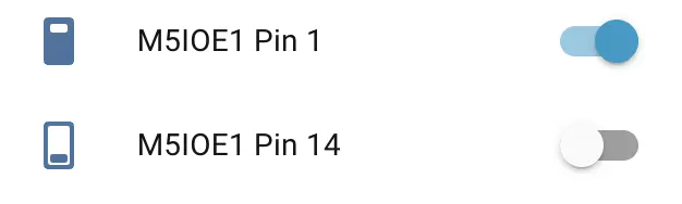
The M5IOE1 Pin 1 switch is used to power the servos. The M5IOE1 Pin 14 switch is enabled by default for NeoPixel-addressable LED strip control. No manual switching is required; the light component controls it automatically.
Power Monitor INA266
This component requires I2C and provides power monitoring (voltage/current). Note: AXP2101 can also monitor battery voltage.
sensor:
 - platform: ina226
    i2c_id: bsp_bus
    address: 0x41
    shunt_resistance: 0.01 ohm
    max_current: 3.2A
    # adc time used for both, Bus Voltage and Shunt Voltage
    adc_time: 140us
    adc_averaging: 128
    update_interval: 60s
    current:
      name: "INA226 Current"
    power:
      name: "INA226 Power"
    bus_voltage:
      name: "INA226 Bus Voltage"
    shunt_voltage:
      name: "INA226 Shunt Voltage"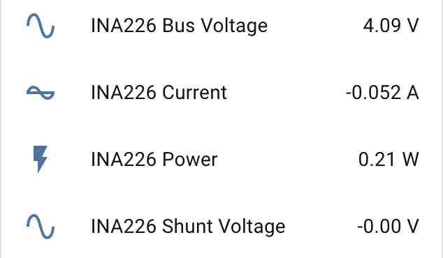
Servos
This component requires UART and provides left-right and up-down head movement for StackChan.
ftservo:
  - platform: scs9009
    address: 1
    id: x_servo
  - platform: scs9009
    address: 2
    id: y_servo

number:
  - platform: ftservo
    ftservo_id: x_servo
    angle:
      id: servo_x_angle
      name: "Servo X Angle"
      min_value: -164
      max_value: 164
      use_raw_angle: false
      angle_offset: 164
      step: 5
    speed:
      id: servo_x_speed
      name: "Servo X Speed"
      min_value: 100
      max_value: 1500
      step: 100

  - platform: ftservo
    ftservo_id: y_servo
    angle:
      id: servo_y_angle
      name: "Servo Y Angle"
      min_value: 0
      max_value: 90
      use_raw_angle: false
      angle_offset: 239
      step: 5
    speed:
      id: servo_y_speed
      name: "Servo Y Speed"
      min_value: 100
      max_value: 1500
      step: 100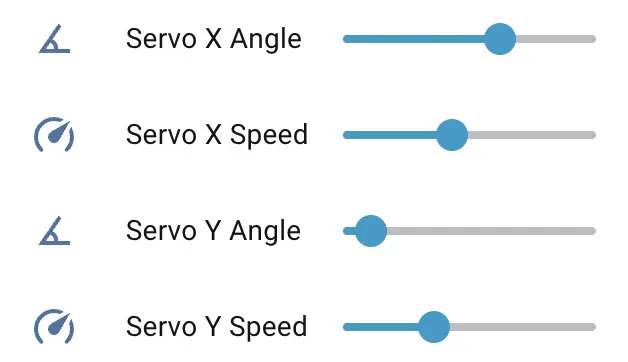
These angles are adjusted to fit StackChan's motion range. X motion is set from -165° to 165°, and Y motion is set from 0° to 90°. Zero refers to 0°.
For default step control, enable:
number:
  - platform: ftservo
    ftservo_id: x_servo
    position:
      id: servo_position
      name: "Servo X Position"
      min_value: 0
max_value: 1024The default step range is 0 to 1024. Adjusting the speed slider controls the servo speed in steps/s.
Servo Calibration
There are two template buttons available in the example YAML configrations:
button:
  - platform: template
    name: "Servo Calibration"
    on_press:
      - lambda: |-
          ESP_LOGD("ftservo", "Start calibration");
          float x_zero = id(servo_x_position).state;
          float y_zero = id(servo_y_position).state;
          // assign offset
          float x_offset = x_zero / 2.844f;
          float y_offset = y_zero / 2.844f;
          // override default offset setting
          id(servo_x_angle)->set_angle_offset(static_cast<int>(x_offset));
          id(servo_y_angle)->set_angle_offset(static_cast<int>(y_offset));
          // indicating we are using calibration value
          id(use_calib_value) = true;
          id(x_servo_zero_step) = static_cast<int>(x_zero);
          id(y_servo_zero_step) = static_cast<int>(y_zero);
      - delay: 1s
      - lambda: |-
          ESP_LOGD("ftservo", "Preferences sync requested");
          global_preferences->sync(); // sync at once
          ESP_LOGD("ftservo", "Done reading and saving zero position, X zero: %d, Y zero %d",
                  id(x_servo_zero_step), id(y_servo_zero_step));

  - platform: template
    name: "Clear Calibration"
    on_press:
      - lambda: |-
          ESP_LOGD("ftservo", "Restore to default settings");
          id(use_calib_value)   = false;
          id(x_servo_zero_step) = ${servo_x_angle_offset};
          id(y_servo_zero_step) = ${servo_y_angle_offset};
      - delay: 1s
      - lambda: |-
          ESP_LOGD("ftservo", "Preferences sync requested");
          global_preferences->sync(); // sync at once
          ESP_LOGD("ftservo", "Done clear calibration");
And serveral components rely on the calibration data:
esphome:
    ...
    # Servo calibration data
    - priority: -100
      then:
        - lambda: |-
            if (id(use_calib_value)) {
              ESP_LOGD("boot", "Restoring calibration: X=%d, Y=%d",
                      id(x_servo_zero_step),
                      id(y_servo_zero_step));
              float x_offset = id(x_servo_zero_step) / 2.844f;
              float y_offset = id(y_servo_zero_step) / 2.844f;
              // override default offset setting
              id(servo_x_angle)->set_angle_offset(static_cast<int>(x_offset));
              id(servo_y_angle)->set_angle_offset(static_cast<int>(y_offset));
            } else {
              ESP_LOGD("boot", "No calibration data, using defaults.");
            }

  - platform: ftservo
    id: x_servo_sensor
    ftservo_id: x_servo
    position:
      id: servo_x_position
      name: "Servo X Position"
      filters:
        - delta: 3.0
      on_value:
        - lambda: |-
            if ( !id(use_calib_value) ) {
              float val = ${servo_x_position_to_angle};
              id(servo_x_angle).publish_state(roundf(val));
            } else {
              float x = id(servo_x_position).state;
              float zero = static_cast<float>(id(x_servo_zero_step));
              float val = (x - zero) * 0.3710f;
              id(servo_x_angle).publish_state(roundf(val));
            }


  - platform: ftservo
    id: y_servo_sensor
    ftservo_id: y_servo
    position:
      id: servo_y_position
      name: "Servo Y Position"
      filters:
        - delta: 3.0
      on_value:
        - lambda: |-
            if ( !id(use_calib_value) ) {
              float val = ${servo_y_position_to_angle};
              id(servo_y_angle).publish_state(roundf(val)); // using angle
            } else {
              float x = id(servo_y_position).state;
              float zero = static_cast<float>(id(y_servo_zero_step));
              float val = (x - zero) * 90.0f / 260.0f;
              id(servo_y_angle).publish_state(roundf(val));
}Connect the StackChan to Home Assistant, calibration steps:
- Move the StackChan to zero position:
Press the
Servo CalibrationbuttonWait for a second for zero position to store into the NVS of ESP32. (If you monitor the serial log, there are logs suggest the NVS writing operation as shown below)
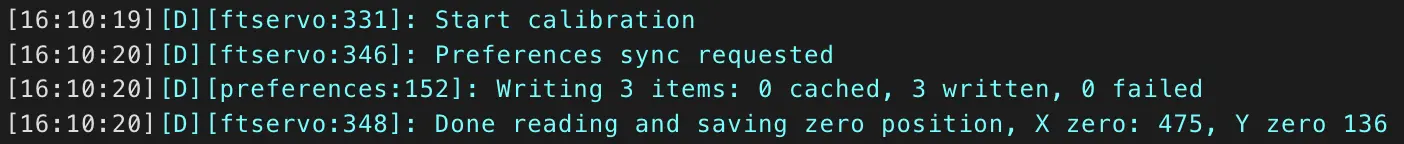
- Try resetting the device, move the number slider slowly to check the calibration results.

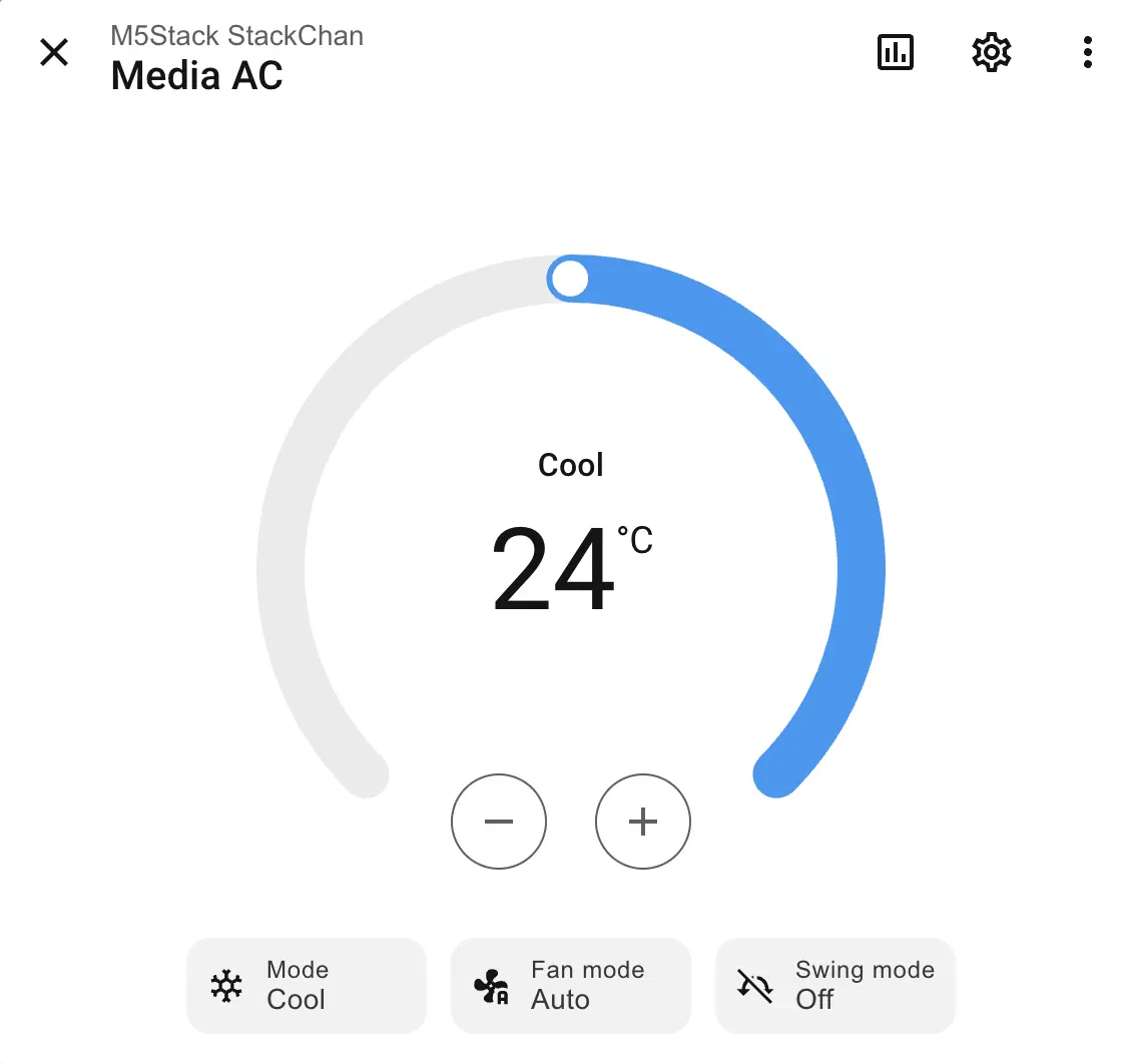
Infrared Transmitter
remote_transmitter:
  pin: GPIO5
  carrier_duty_percent: 50%
non_blocking: trueThe infrared component can be used to create IR environment control devices such as air conditioners. For example:
climate:
  - platform: coolix
    name: "Media AC"
    visual:
      min_temperature: 18
      max_temperature: 30
      temperature_step: 1
Capacitive Touch Sensor Si12T
This component requires I2C and can provide touch results when touching StackChan's head using text_sensor.
si12t:
  id: touch_hub
  i2c_id: bsp_bus

text_sensor:
  - platform: si12t
    name: "Touch Sensor 1"
    channel: CH_1
    update_interval: 1s
  - platform: si12t
    name: "Touch Sensor 2"
    channel: CH_2
    update_interval: 1s
  - platform: si12t
    name: "Touch Sensor 3"
    channel: CH_3
    update_interval: 1s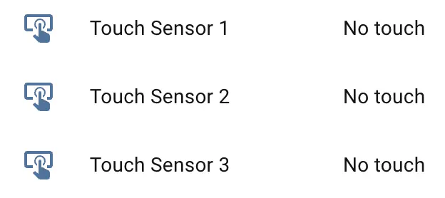
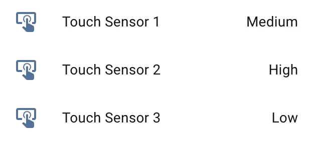
Touch results are reported to frontend sensors as HIGH, MEDIUM, and LOW, corresponding to high, medium, and low intensity. No touch means no touch was detected.
NFC ST25R3916 (WIP)
This feature requires I2C.
RGB Light Bar
This feature depends on the NeoPixel driver on the M5IOE1 board and must be enabled in M5IOE1:
light:
  - platform: m5ioe1
    id: stackchan_light_bar
    name: "StackChan Light Bar"
    icon: mdi:led-strip
    num_led: 12
    effects:
      - random:
          name: "Random"
          transition_length: 1s
          update_interval: 1s
      - addressable_rainbow:
      - addressable_rainbow:
          name: Rainbow Effect With Custom Values
          speed: 10
          width: 50
      - addressable_twinkle:
      - addressable_twinkle:
          name: Twinkle Effect With Custom Values
          twinkle_probability: 5%
progress_interval: 4msIt also requires BUS power to supply 5V. Enable BOOST EN and BUS OUT EN switches (these GPIO switches are on the AW9523B IO expander):
switch:
  - platform: gpio
    name: "BOOST_EN"
    pin:
      aw9523b_id: aw9523b_hub
      number: 15
    restore_mode: RESTORE_DEFAULT_ON

  - platform: gpio
    name: "BUS_OUT_EN"
    pin:
      aw9523b_id: aw9523b_hub
      number: 1
    restore_mode: RESTORE_DEFAULT_ON
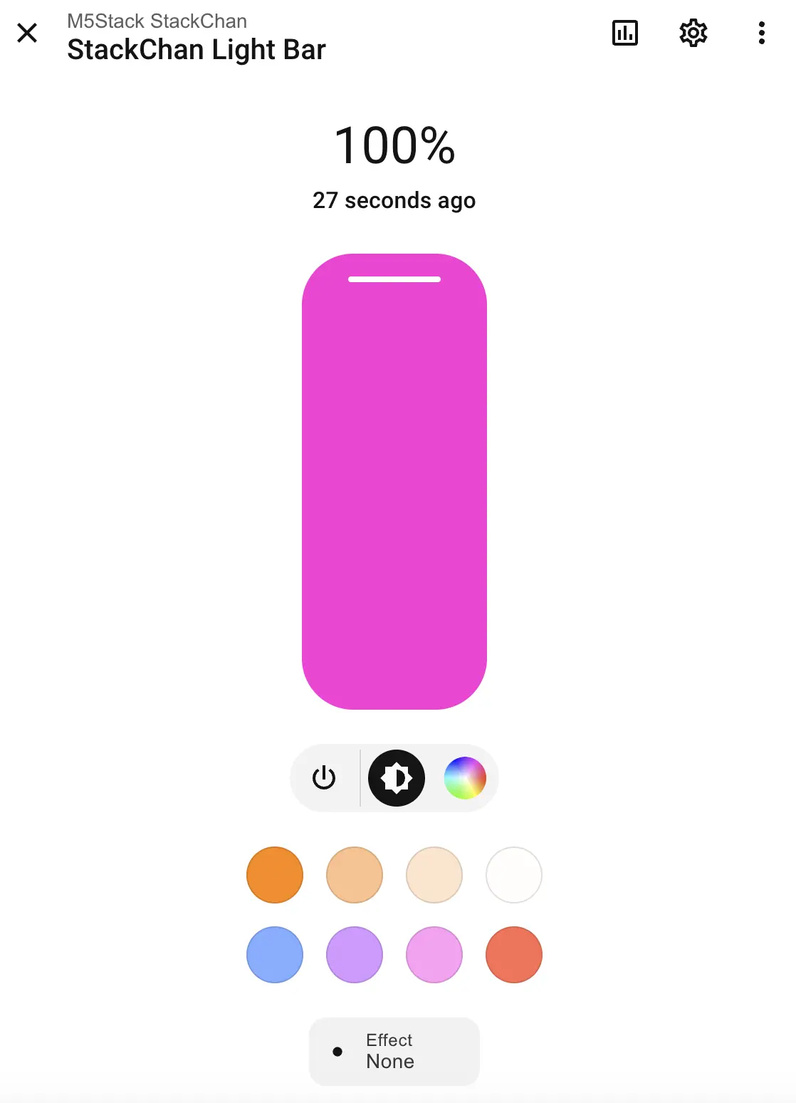
Enable light effects:
Infrared Receiver
remote_receiver:
pin: GPIO10If the controlled device supports feedback, use remote_receiver to receive and process it.