

Home Assistant
传感器
Chain DualKey Home Assistant 集成
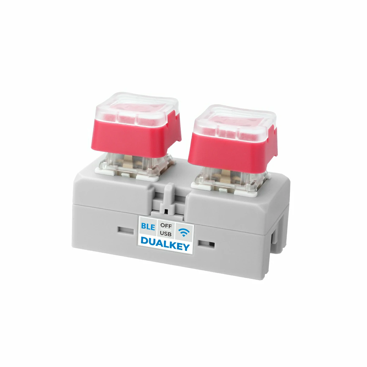
本教程将介绍如何使用 Chain DualKey 可编程双键开发板集成至 Home Assistant,实现按键与扩展模块控制。

1. 准备工作
环境准备
- 参考 Home Assistant 官方文档安装 Home Assistant。
- 参考 ESPHome 官方文档 完成 ESPHome Device Builder 插件安装。(注意:本教程基于
ESPHome 2025.1.2版本编写,如遇编译错误,建议先切换至该版本进行验证。)
硬件产品
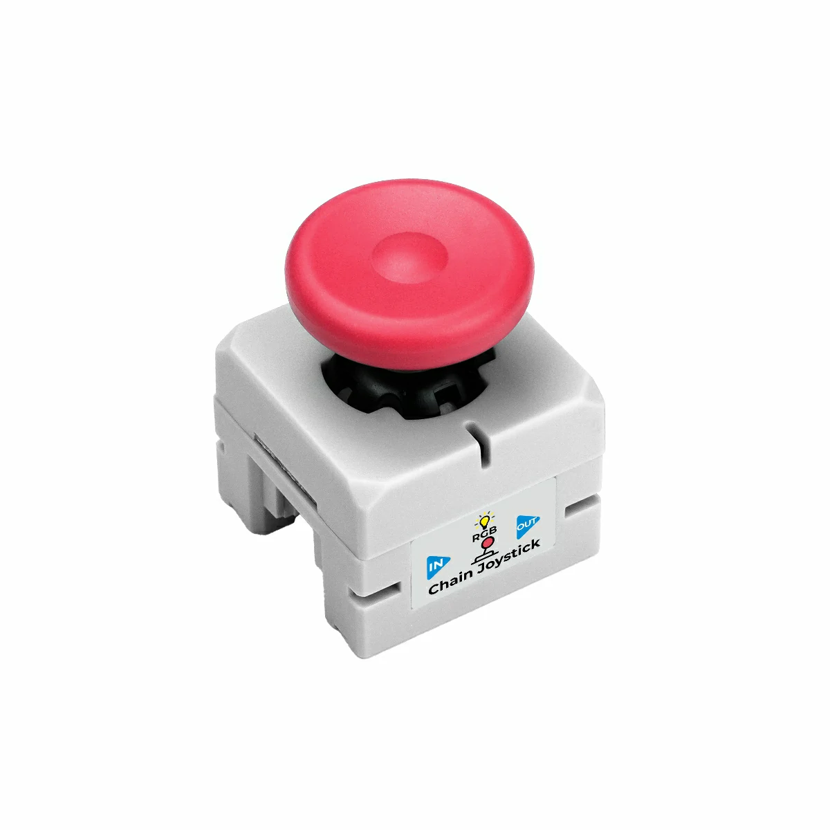
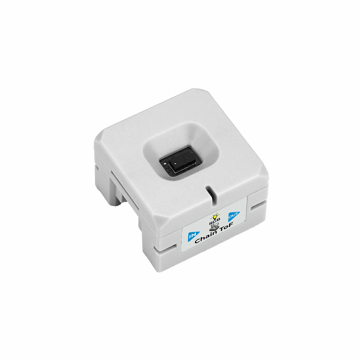
2. 固件编译 & 烧录
本小节将说明如何基于 yaml 配置文件重新编译项目,便于二次开发、功能修改或新增功能。
编译时长
首次构建可能需要一些时间,具体取决于 Home Assistant 主机的性能和网络质量。
创建设备
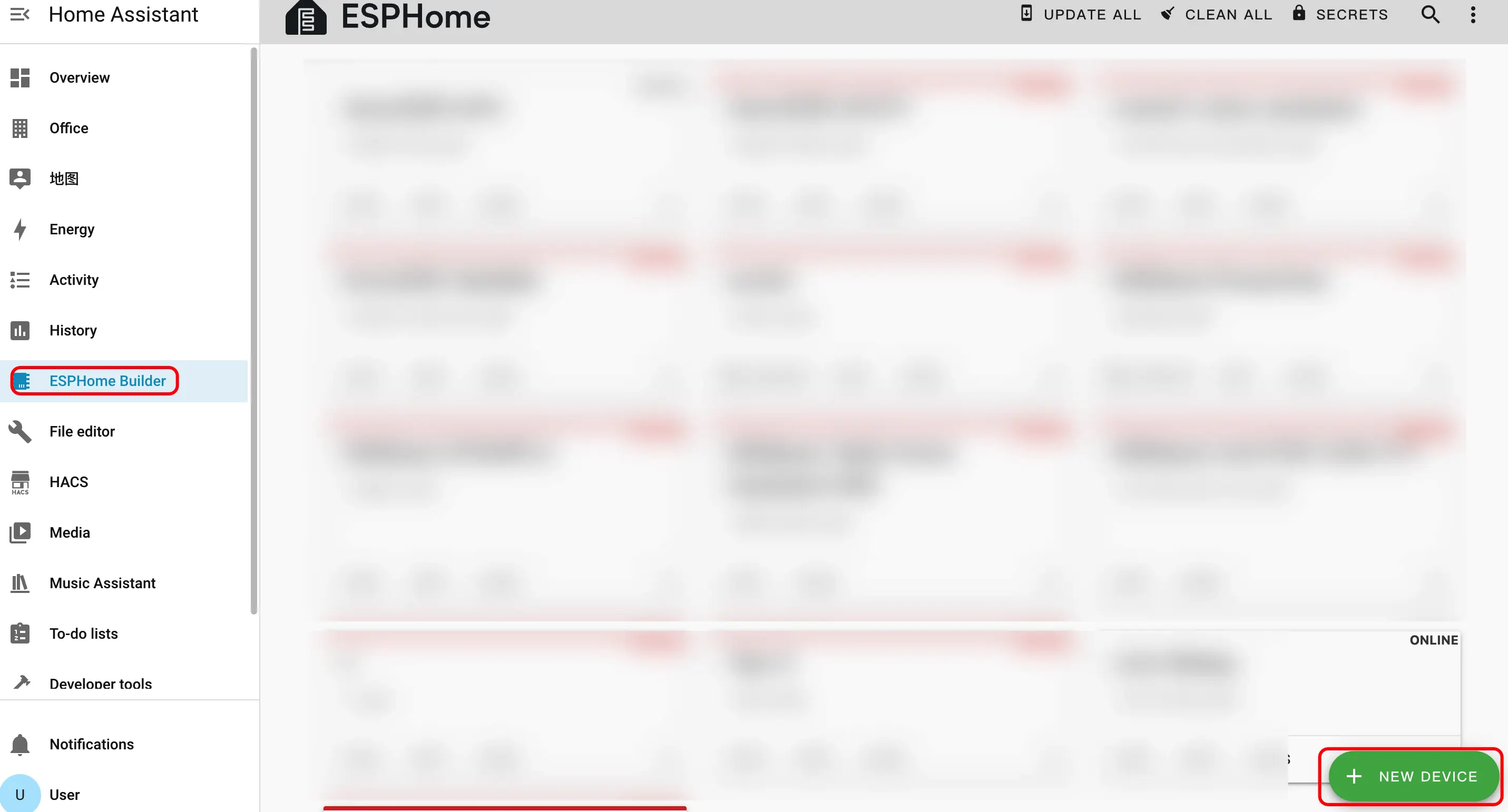
- 创建新设备。点击右下角的绿色按钮创建设备。
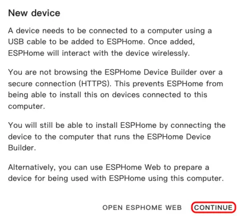
- 创建设备名称。
- 点击
CONTINUE。
- 点击
New Device Setup。
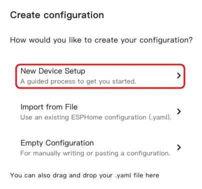
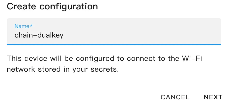
- 输入设备名称后点击
NEXT。
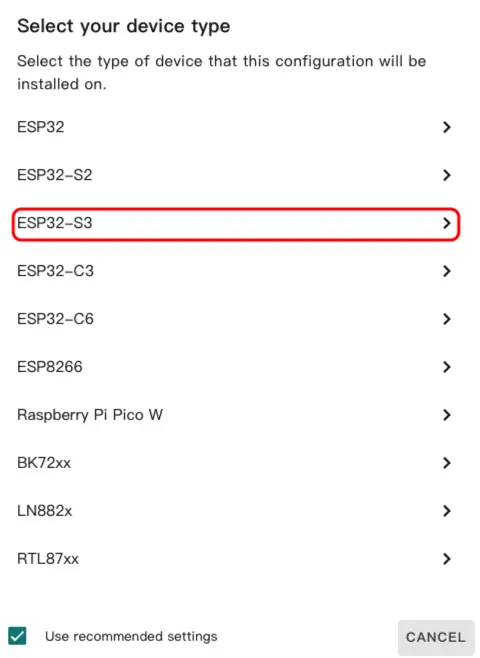
- 选择设备类型。
- 点击
ESP32-S3。
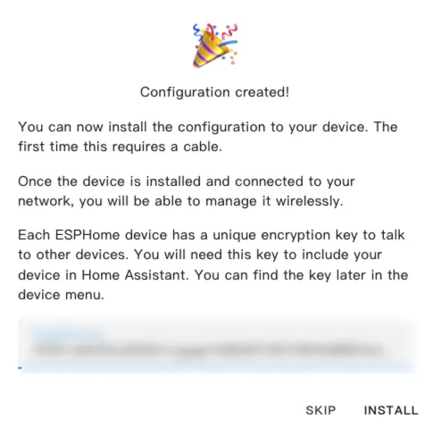
- 点击
SKIP。
修改配置
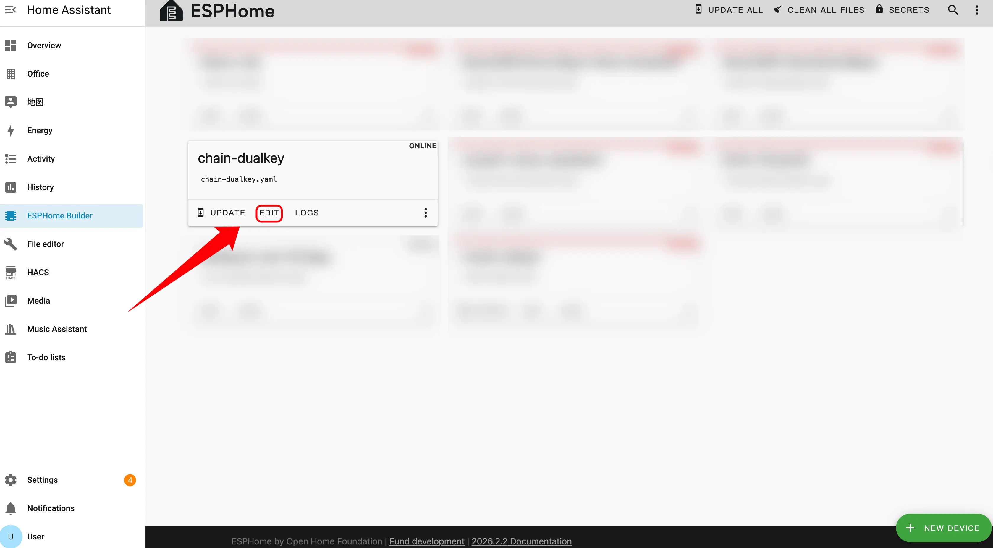
- 点击
EDIT编辑 YAML 文件,通过 YAML 文件自定义设备功能。
Master 作为系统的主控制器。在连接扩展传感器时,需要正确区分连接方向以及 ID 编号顺序。
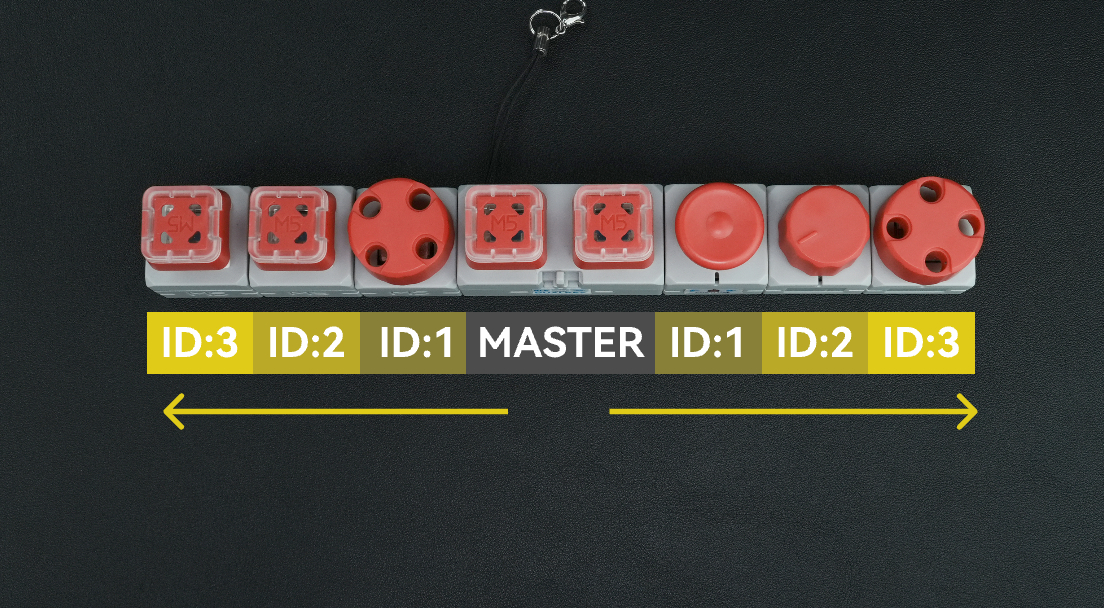
方向选择
根据扩展传感器连接在 Master 的哪一侧,选择对应的 uart_id:
- 连接在 Master 左侧 → 使用
chain_uart_left。 - 连接在 Master 右侧 → 使用
chain_uart_right。
ID 编号规则
chain_id 表示扩展传感器相对于 Master 的位置:
- 编号从距离 Master 最近的模块开始。
- ID 依次递增(ID:1 → ID:2 → ID:3 …)。
- 左右两侧分别独立编号。
- 可参考上图确定正确的顺序。
配置示例
uart_id:chain_uart_left。chain_id:1。
Chain DualKey
uart:
  - id: chain_uart_right
    tx_pin: GPIO6
    rx_pin: GPIO5
    baud_rate: 115200

  - id: chain_uart_left
    tx_pin: GPIO48
    rx_pin: GPIO47
    baud_rate: 115200

sensor:
  - platform: adc
    pin: GPIO10
    name: "ADC_BAT"
    update_interval: 1s

  - platform: adc
    pin: GPIO2
    name: "ADC_VBUS"
    update_interval: 1s

  - platform: adc
    pin: GPIO9
    name: "ADC_CHARGE"
    update_interval: 1s

output:
  - platform: gpio
    id: pwr_en
    pin: GPIO40

light:
  - platform: esp32_rmt_led_strip
    id: key_light_raw
    internal: true
    pin: GPIO21
    num_leds: 2
    chipset: ws2812
    rgb_order: GRB
    restore_mode: ALWAYS_OFF

  - platform: partition
    name: "Key Light 1"
    id: key_light_1
    segments:
      - id: key_light_raw
        from: 0
        to: 0

  - platform: partition
    name: "Key Light 2"
    id: key_light_2
    segments:
      - id: key_light_raw
        from: 1
        to: 1

binary_sensor:
  - platform: gpio
    name: "KEY_2"
    pin:
      number: GPIO17
      inverted: true
      mode: INPUT_PULLUP
    filters:
      - delayed_on: 10ms
      - delayed_off: 10ms

    on_press:
      - light.turn_on:
          id: key_light_2
          transition_length: 0ms

    on_release:
      - light.turn_off: key_light_2

  - platform: gpio
    name: "KEY_1"
    pin:
      number: GPIO0
      inverted: true
      mode: INPUT_PULLUP
    filters:
      - delayed_on: 10ms
      - delayed_off: 10ms

    on_press:
      - light.turn_on:
          id: key_light_1
          transition_length: 0ms

    on_release:
      - light.turn_off: key_light_1

  - platform: gpio
    name: "SWITCH_1"
    pin:
      number: GPIO7
      mode: INPUT

  - platform: gpio
    name: "SWITCH_2"
    pin:
      number: GPIO8
mode: INPUTChain Key
external_components:
  - source: github://m5stack/esphome-yaml/components
    components: [m5stack_chain_key]
    refresh: 0s

binary_sensor:
  - platform: m5stack_chain_key
    id: chain_key_1
    name: "Chain Key Button"
    uart_id: xx
    chain_id: xx
    update_interval: 50ms

output:
  - platform: m5stack_chain_key
    id: chain_key_rgb_r
    chain_key_id: chain_key_1
    channel: rgb_red

  - platform: m5stack_chain_key
    id: chain_key_rgb_g
    chain_key_id: chain_key_1
    channel: rgb_green

  - platform: m5stack_chain_key
    id: chain_key_rgb_b
    chain_key_id: chain_key_1
    channel: rgb_blue

light:
  - platform: rgb
    name: "Key RGB"
    red: chain_key_rgb_r
    green: chain_key_rgb_g
blue: chain_key_rgb_bChain Angle
external_components:
  - source: github://m5stack/esphome-yaml/components
    components: [m5stack_chain_angle]
    refresh: 0s

sensor:
  - platform: m5stack_chain_angle
    id: chain_angle_1
    name: "Chain Angle"
    uart_id: xx
    chain_id: xx
    update_interval: 50ms

output:
  - platform: m5stack_chain_angle
    id: chain_angle_rgb_r
    chain_angle_id: chain_angle_1
    channel: rgb_red

  - platform: m5stack_chain_angle
    id: chain_angle_rgb_g
    chain_angle_id: chain_angle_1
    channel: rgb_green

  - platform: m5stack_chain_angle
    id: chain_angle_rgb_b
    chain_angle_id: chain_angle_1
    channel: rgb_blue

light:
  - platform: rgb
    name: "Angle RGB"
    red: chain_angle_rgb_r
    green: chain_angle_rgb_g
blue: chain_angle_rgb_bChain Encoder
external_components:
  - source: github://m5stack/esphome-yaml/components
    components: [m5stack_chain_encoder]
    refresh: 0s

sensor:
  - platform: m5stack_chain_encoder
    id: chain_encoder_1
    name: "Chain Encoder"
    uart_id: xx
    chain_id: xx
    update_interval: 100ms

output:
  - platform: m5stack_chain_encoder
    id: chain_encoder_rgb_r
    chain_encoder_id: chain_encoder_1
    channel: rgb_red

  - platform: m5stack_chain_encoder
    id: chain_encoder_rgb_g
    chain_encoder_id: chain_encoder_1
    channel: rgb_green

  - platform: m5stack_chain_encoder
    id: chain_encoder_rgb_b
    chain_encoder_id: chain_encoder_1
    channel: rgb_blue

light:
  - platform: rgb
    name: "Encoder RGB"
    red: chain_encoder_rgb_r
    green: chain_encoder_rgb_g
    blue: chain_encoder_rgb_b

binary_sensor:
  - platform: m5stack_chain_encoder
    name: "Encoder Button"
chain_encoder_id: chain_encoder_1Chain Joystick
external_components:
  - source: github://m5stack/esphome-yaml/components
    components: [m5stack_chain_joystick]
    refresh: 0s

sensor:
  - platform: m5stack_chain_joystick
    id: chain_joystick_x
    name: "Chain Joystick X"
    uart_id: xx
    chain_id: xx
    axis: x
    update_interval: 50ms

  - platform: m5stack_chain_joystick
    name: "Chain Joystick Y"
    uart_id: xx
    chain_id: xx
    axis: y
    update_interval: 50ms

output:
  - platform: m5stack_chain_joystick
    id: chain_joystick_rgb_r
    chain_joystick_id: chain_joystick_x
    channel: rgb_red

  - platform: m5stack_chain_joystick
    id: chain_joystick_rgb_g
    chain_joystick_id: chain_joystick_x
    channel: rgb_green

  - platform: m5stack_chain_joystick
    id: chain_joystick_rgb_b
    chain_joystick_id: chain_joystick_x
    channel: rgb_blue

light:
  - platform: rgb
    name: "Joystick RGB"
    red: chain_joystick_rgb_r
    green: chain_joystick_rgb_g
    blue: chain_joystick_rgb_b

binary_sensor:
  - platform: m5stack_chain_joystick
    name: "Joystick Button"
chain_joystick_id: chain_joystick_xChain ToF
external_components:
  - source: github://m5stack/esphome-yaml/components
    components: [m5stack_chain_tof]
    refresh: 0s

sensor:
  - platform: m5stack_chain_tof
    id: chain_tof_1
    name: "Chain ToF"
    uart_id: xx
    chain_id: xx
    update_interval: 100ms

output:
  - platform: m5stack_chain_tof
    id: chain_tof_rgb_r
    m5stack_chain_tof_id: chain_tof_1
    channel: rgb_red

  - platform: m5stack_chain_tof
    id: chain_tof_rgb_g
    m5stack_chain_tof_id: chain_tof_1
    channel: rgb_green

  - platform: m5stack_chain_tof
    id: chain_tof_rgb_b
    m5stack_chain_tof_id: chain_tof_1
    channel: rgb_blue

light:
  - platform: rgb
    name: "ToF RGB"
    red: chain_tof_rgb_r
    green: chain_tof_rgb_g
blue: chain_tof_rgb_b示例
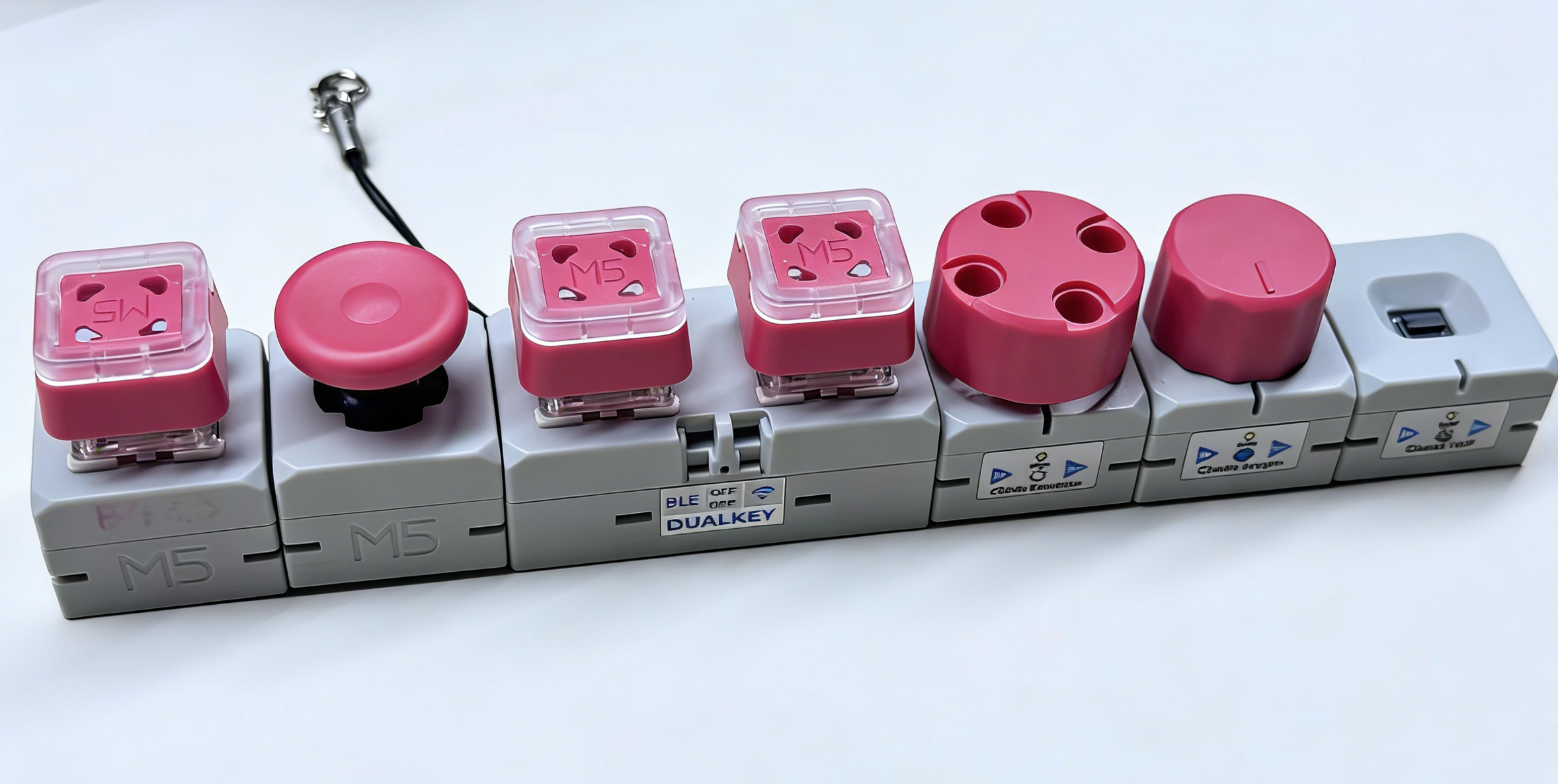
下面的代码示例是根据上图所示的连接顺序进行配置的。
外部组件
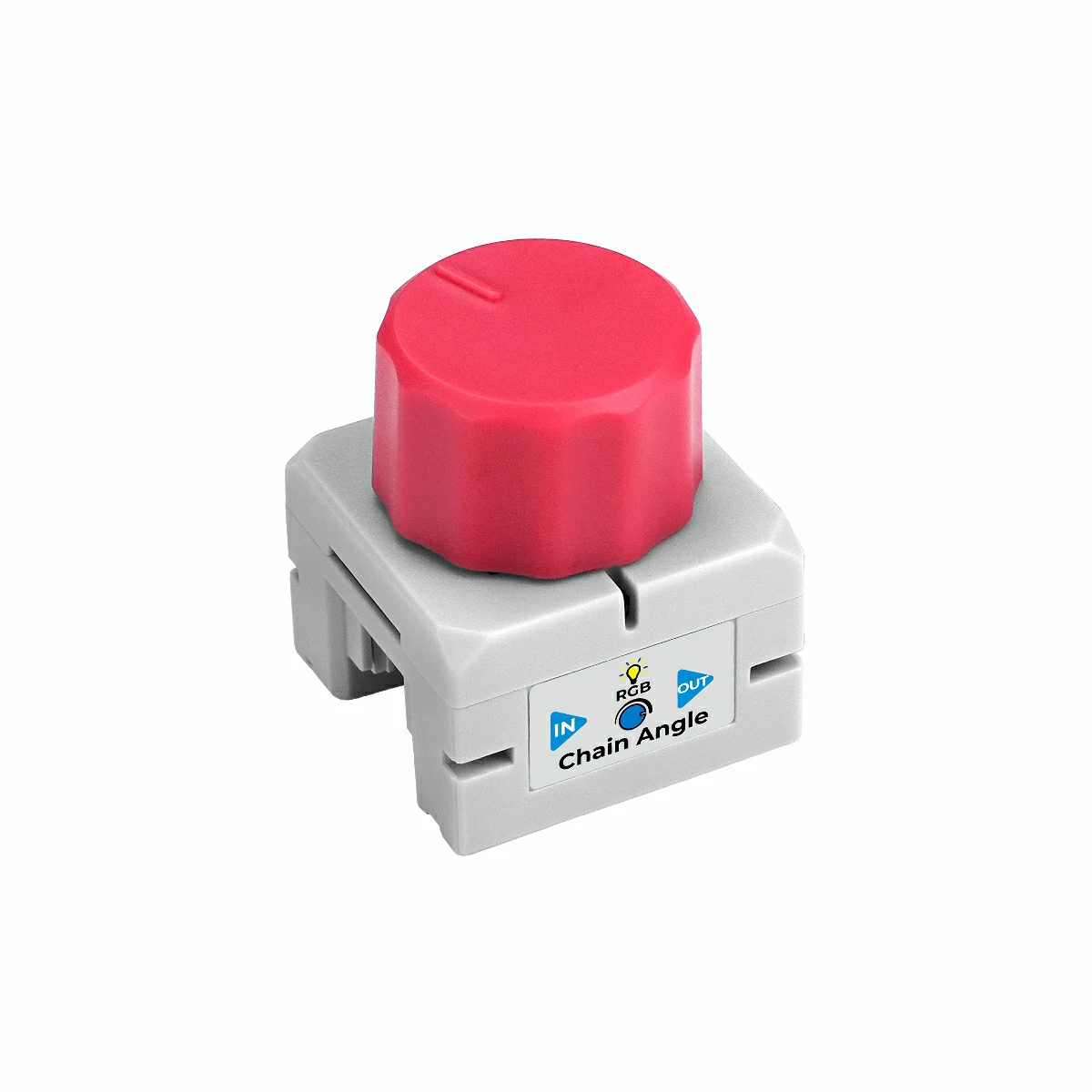
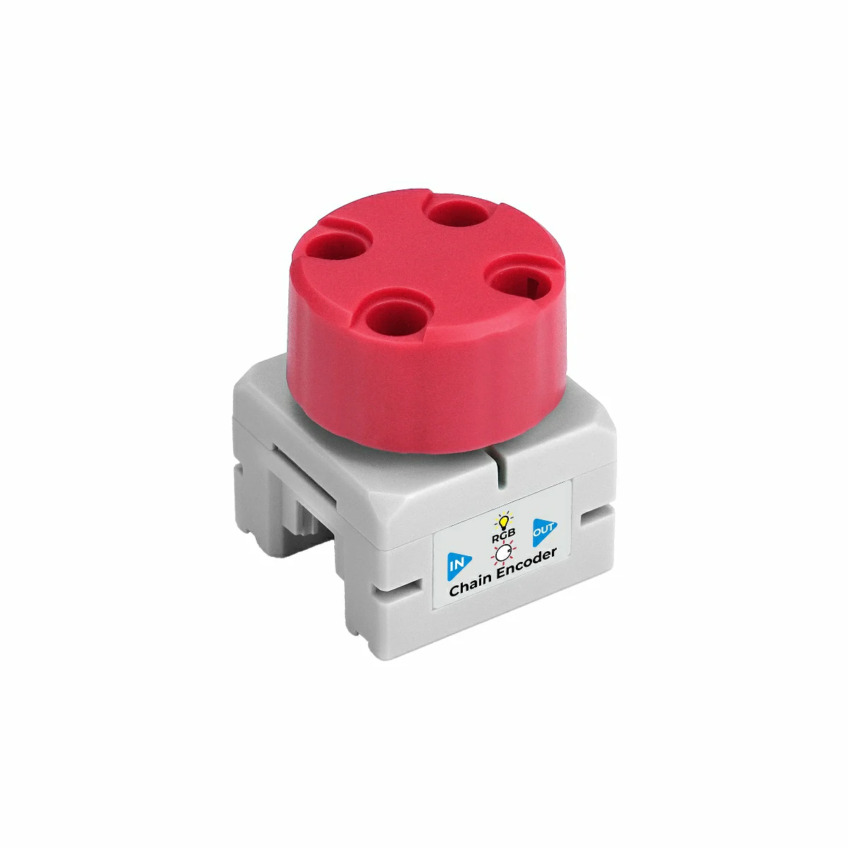
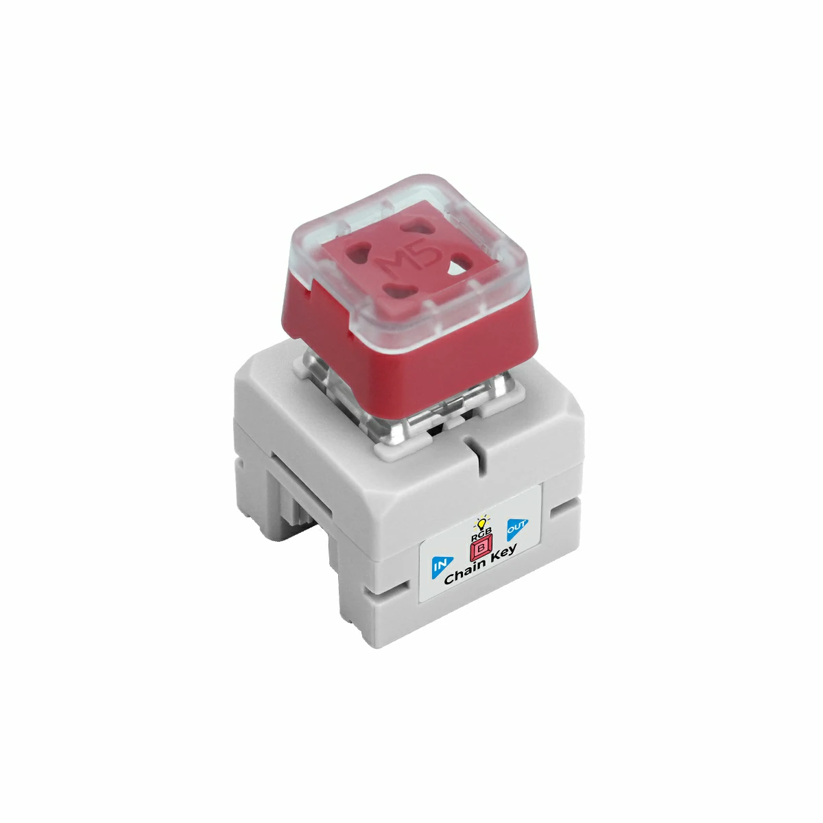
使用的模块:Chain Angle、Chain Encoder、Chain ToF、Chain Joystick、Chain Key。
- 添加 External 组件。此配置块用于引入所有 Chain 系列相关的外部组件。如果某个模块(例如 Chain Encoder 或 Chain ToF)不使用,可以从 components 列表中删除对应项。
external_components:
  - source: github://m5stack/esphome-yaml/components
    components:
      [
        m5stack_chain_angle,
        m5stack_chain_encoder,
        m5stack_chain_tof,
        m5stack_chain_joystick,
        m5stack_chain_key,
      ]
refresh: 0sUART 组件
使用的模块:主控左 / 右侧 HY2.0 接口上的所有 Chain 系列模块共用的 UART 总线。
- 添加 Uart 组件。在本示例中,
chain_uart_right和chain_uart_left分别对应主控右侧和左侧的 HY2.0 接口。后续 Chain 模组的uart_id需要与实际连接方向保持一致。
captive_portal:
uart:
  - id: chain_uart_right
    tx_pin: GPIO6
    rx_pin: GPIO5
    baud_rate: 115200

  - id: chain_uart_left
    tx_pin: GPIO48
    rx_pin: GPIO47
baud_rate: 115200传感器组件
使用的模块:Chain Encoder、Chain Angle、Chain ToF、Chain Joystick(X/Y)、DualKey 电池相关 ADC 传感器。
- 添加 Sensor 组件。在本示例中,主控右侧按顺序连接了 Chain Encoder(ID 1)、Chain Angle(ID 2)、Chain ToF(ID 3),左侧连接了 Chain Joystick(ID 1,X/Y 两个轴)。同时还启用了电池电量相关的 ADC 通道(BAT、VBUS、CHARGE)作为传感器。
sensor:
  - platform: m5stack_chain_encoder
    id: chain_encoder_1
    name: "Encoder"
    uart_id: chain_uart_right
    chain_id: 1
    update_interval: 100ms

  - platform: m5stack_chain_tof
    id: chain_tof_1
    name: "ToF Distance"
    uart_id: chain_uart_right
    chain_id: 3
    update_interval: 100ms

  - platform: m5stack_chain_angle
    id: chain_angle_1
    name: "Angle"
    uart_id: chain_uart_right
    chain_id: 2
    update_interval: 100ms

  - platform: m5stack_chain_joystick
    id: chain_joystick_x
    name: "Joystick X"
    uart_id: chain_uart_left
    chain_id: 1
    axis: x
    update_interval: 100ms

  - platform: m5stack_chain_joystick
    name: "Joystick Y"
    uart_id: chain_uart_left
    chain_id: 1
    axis: y
    update_interval: 100ms

  - platform: adc
    pin: GPIO10
    name: "ADC_BAT"
    update_interval: 1s

  - platform: adc
    pin: GPIO2
    name: "ADC_VBUS"
    update_interval: 1s

  - platform: adc
    pin: GPIO9
    name: "ADC_CHARGE"
update_interval: 1s输出组件
使用的模块:Chain Encoder、Chain Key、Chain Joystick、Chain Angle、Chain ToF 的 RGB 灯以及 DualKey 的电源控制。
- 添加 Output 组件。其中
pwr_enGPIO 输出用于控制 Chain 扩展总线的供电,通常需要保持开启,以保证连接在总线上的模块可以正常工作。
output:
  - platform: gpio
    id: pwr_en
    pin: GPIO40

  - platform: m5stack_chain_encoder
    id: chain_encoder_rgb_r
    chain_encoder_id: chain_encoder_1
    channel: rgb_red

  - platform: m5stack_chain_encoder
    id: chain_encoder_rgb_g
    chain_encoder_id: chain_encoder_1
    channel: rgb_green

  - platform: m5stack_chain_encoder
    id: chain_encoder_rgb_b
    chain_encoder_id: chain_encoder_1
    channel: rgb_blue

  - platform: m5stack_chain_key
    id: chain_key_rgb_r
    chain_key_id: chain_key_1
    channel: rgb_red

  - platform: m5stack_chain_key
    id: chain_key_rgb_g
    chain_key_id: chain_key_1
    channel: rgb_green

  - platform: m5stack_chain_key
    id: chain_key_rgb_b
    chain_key_id: chain_key_1
    channel: rgb_blue

  - platform: m5stack_chain_joystick
    id: chain_joystick_rgb_r
    chain_joystick_id: chain_joystick_x
    channel: rgb_red

  - platform: m5stack_chain_joystick
    id: chain_joystick_rgb_g
    chain_joystick_id: chain_joystick_x
    channel: rgb_green

  - platform: m5stack_chain_joystick
    id: chain_joystick_rgb_b
    chain_joystick_id: chain_joystick_x
    channel: rgb_blue

  - platform: m5stack_chain_angle
    id: chain_angle_rgb_r
    chain_angle_id: chain_angle_1
    channel: rgb_red

  - platform: m5stack_chain_angle
    id: chain_angle_rgb_g
    chain_angle_id: chain_angle_1
    channel: rgb_green

  - platform: m5stack_chain_angle
    id: chain_angle_rgb_b
    chain_angle_id: chain_angle_1
    channel: rgb_blue

  - platform: m5stack_chain_tof
    id: chain_tof_rgb_r
    m5stack_chain_tof_id: chain_tof_1
    channel: rgb_red

  - platform: m5stack_chain_tof
    id: chain_tof_rgb_g
    m5stack_chain_tof_id: chain_tof_1
    channel: rgb_green

  - platform: m5stack_chain_tof
    id: chain_tof_rgb_b
    m5stack_chain_tof_id: chain_tof_1
channel: rgb_blue灯光组件
使用的模块:DualKey 上的 WS2812 按键灯,以及各 Chain 模组上的 RGB 指示灯。
- 添加 Light 组件。这一部分配置了 DualKey 上每个按键的 RGB 背光(通过
key_light_raw分区成key_light_1和key_light_2),同时也为各个 Chain 模组定义了对应的 RGB 灯光实体,方便在 Home Assistant 中分别控制。
light:
  - platform: esp32_rmt_led_strip
    id: key_light_raw
    internal: true
    pin: GPIO21
    num_leds: 2
    chipset: ws2812
    rgb_order: GRB
    restore_mode: ALWAYS_OFF

  - platform: partition
    name: "Key1 LED"
    id: key_light_1
    segments:
      - id: key_light_raw
        from: 1
        to: 1

  - platform: partition
    name: "Key2 LED"
    id: key_light_2
    segments:
      - id: key_light_raw
        from: 0
        to: 0

  - platform: rgb
    name: "Encoder RGB"
    red: chain_encoder_rgb_r
    green: chain_encoder_rgb_g
    blue: chain_encoder_rgb_b

  - platform: rgb
    name: "Key RGB"
    red: chain_key_rgb_r
    green: chain_key_rgb_g
    blue: chain_key_rgb_b

  - platform: rgb
    name: "Joystick RGB"
    red: chain_joystick_rgb_r
    green: chain_joystick_rgb_g
    blue: chain_joystick_rgb_b

  - platform: rgb
    name: "Angle RGB"
    red: chain_angle_rgb_r
    green: chain_angle_rgb_g
    blue: chain_angle_rgb_b

  - platform: rgb
    name: "ToF RGB"
    red: chain_tof_rgb_r
    green: chain_tof_rgb_g
blue: chain_tof_rgb_b二进制传感器组件
使用的模块:DualKey 上的机械按键和侧边拨码开关,以及 Chain Key、Chain Encoder、Chain Joystick 上的按键。
- 添加 Binary Sensor 组件。这一部分定义了所有与按键相关的输入:两个机械键(
KEY 1、KEY 2)及其对应的背光联动、总线上一个 Chain Key 模组的按键、编码器按键、摇杆按键,以及两个侧边开关(SWITCH 1、SWITCH 2)。你可以根据实际使用场景在 Home Assistant 中重命名这些实体。
binary_sensor:
  - platform: gpio
    name: "KEY 2"
    pin:
      number: GPIO17
      inverted: true
      mode: INPUT_PULLUP
    filters:
      - delayed_on: 10ms
      - delayed_off: 10ms

    on_press:
      - light.turn_on:
          id: key_light_2
          transition_length: 0ms

    on_release:
      - light.turn_off: key_light_2

  - platform: gpio
    name: "KEY 1"
    pin:
      number: GPIO0
      inverted: true
      mode: INPUT_PULLUP
    filters:
      - delayed_on: 10ms
      - delayed_off: 10ms

    on_press:
      - light.turn_on:
          id: key_light_1
          transition_length: 0ms

    on_release:
      - light.turn_off: key_light_1

  - platform: m5stack_chain_key
    id: chain_key_1
    name: "Key Module Button"
    uart_id: chain_uart_left
    chain_id: 2
    update_interval: 50ms

  - platform: m5stack_chain_encoder
    name: "Encoder Button"
    chain_encoder_id: chain_encoder_1

  - platform: m5stack_chain_joystick
    name: "Joystick Button"
    chain_joystick_id: chain_joystick_x

  - platform: gpio
    name: "SWITCH 1"
    pin:
      number: GPIO7
      mode: INPUT

  - platform: gpio
    name: "SWITCH 2"
    pin:
      number: GPIO8
mode: INPUT编译固件
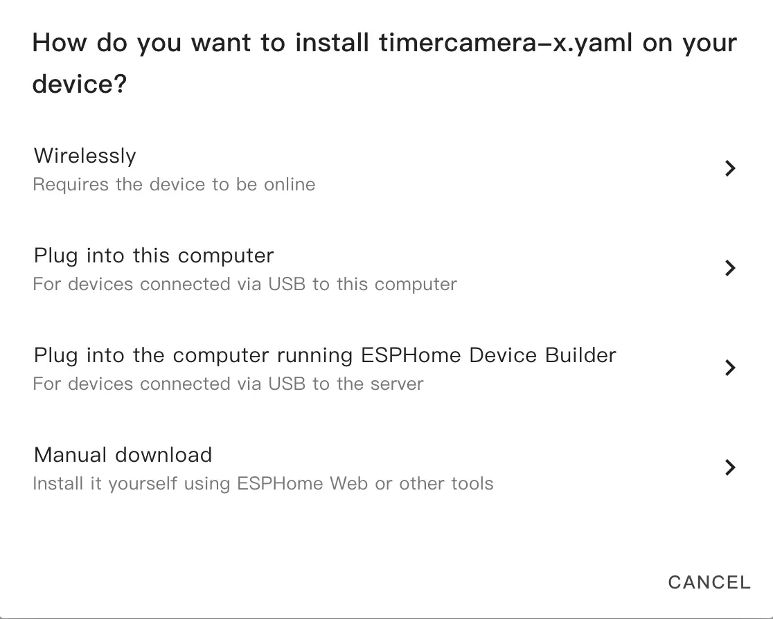
- 修改完成后,点击右上角的
SAVE和INSTALL,在弹出的对话框中选择Manual Download。
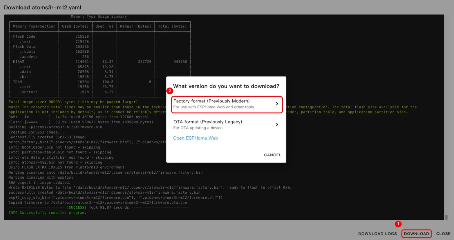
- 固件编译完成后,点击
Download,并选择Factory format(Previously Modern)选项下载固件。
配置示例
点击 m5stack_chain 查看完整示例配置。
烧录固件
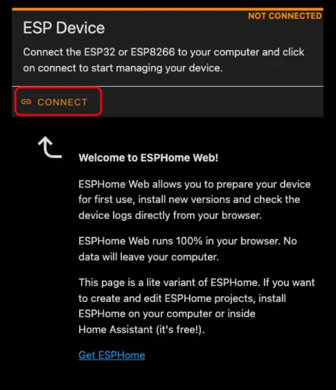
- 使用 USB Type-C 数据线将设备连接到主机。打开 ESPHome Web,点击
CONNECT连接设备。
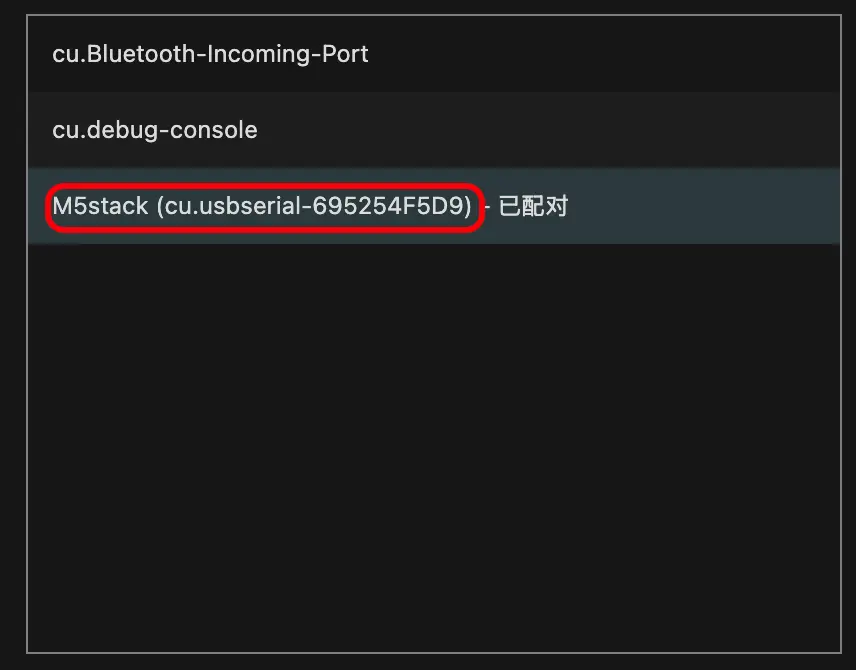
- 找到对应的串口号。
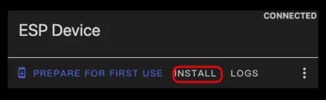
- 点击
INSTALL。
- 选择编译好的固件进行上传。
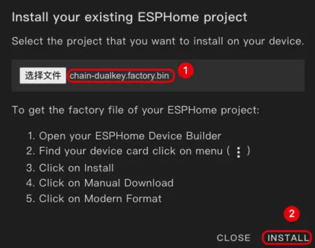
- 固件烧录完成后,需要重新上电以完成硬件复位。
3. 开始使用
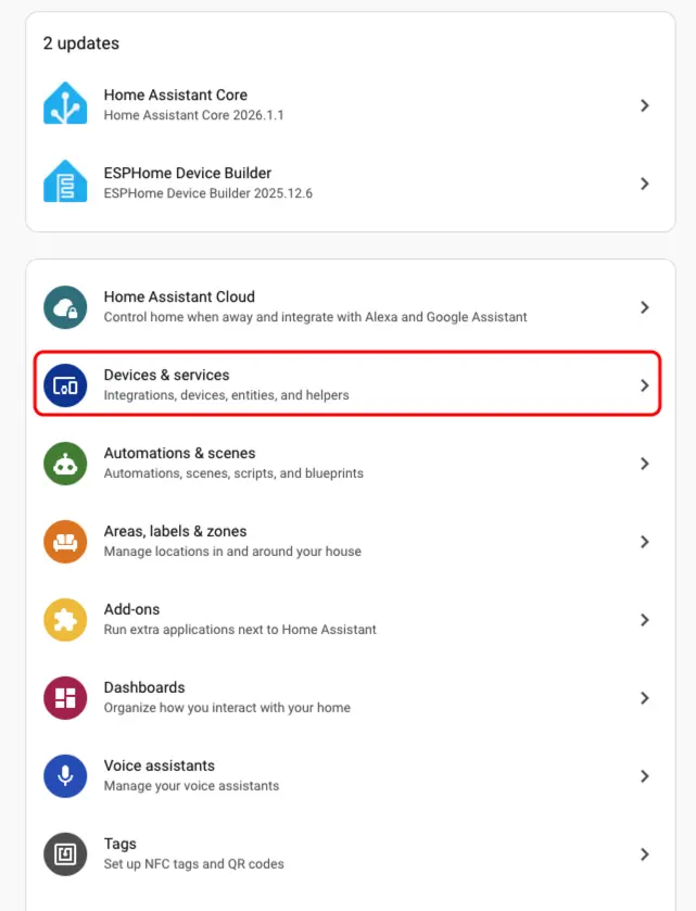
- 在 Home Assistant 中点击
Settings>Devices & Services查看设备。
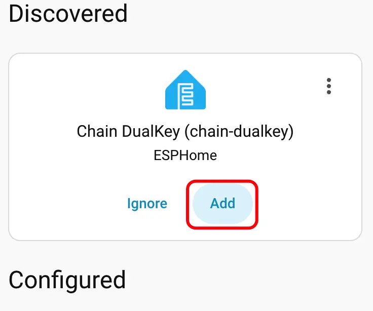
- 我们可以在
Discovered区域中找到对应的设备。
- 添加设备后,数据会正确显示。
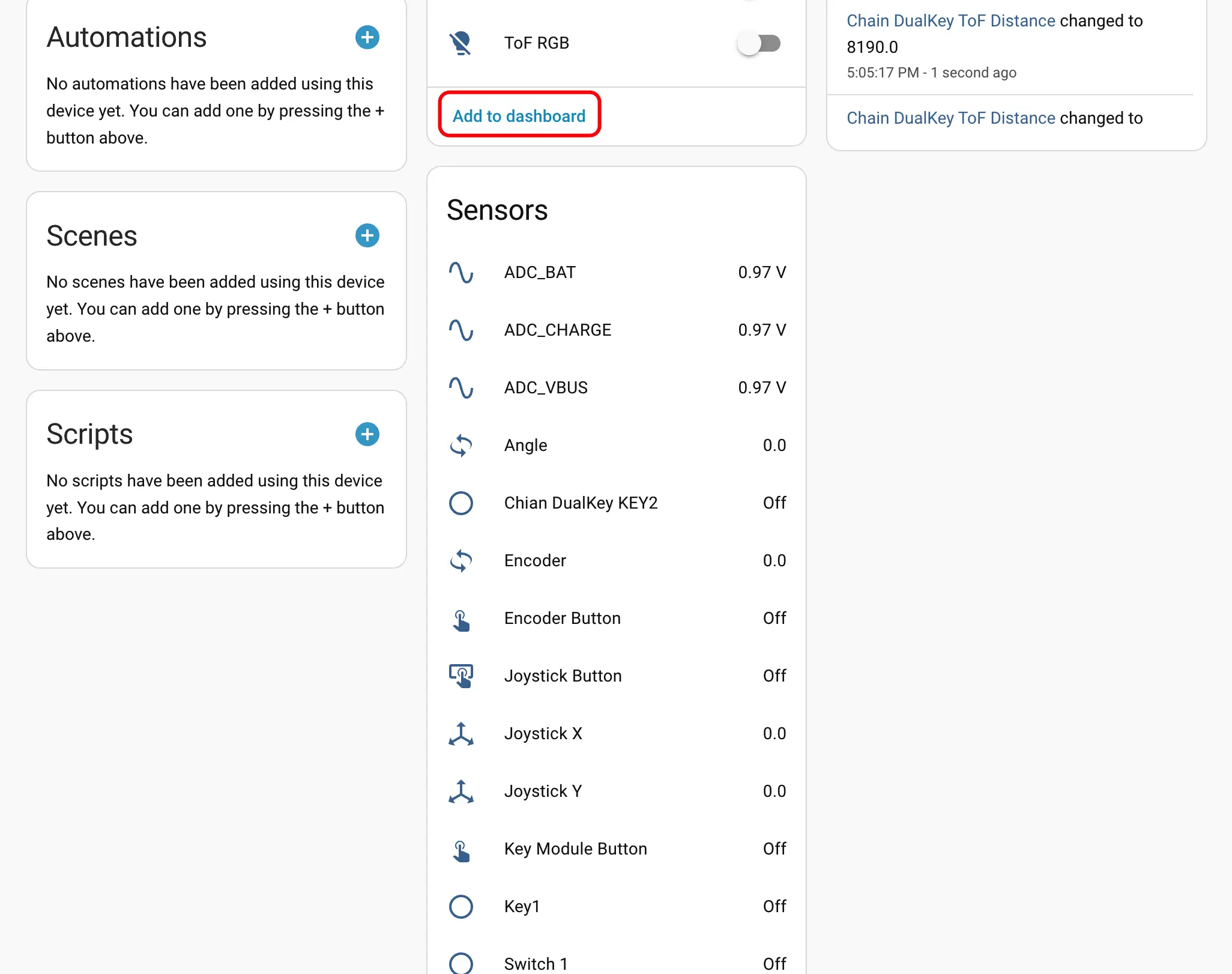
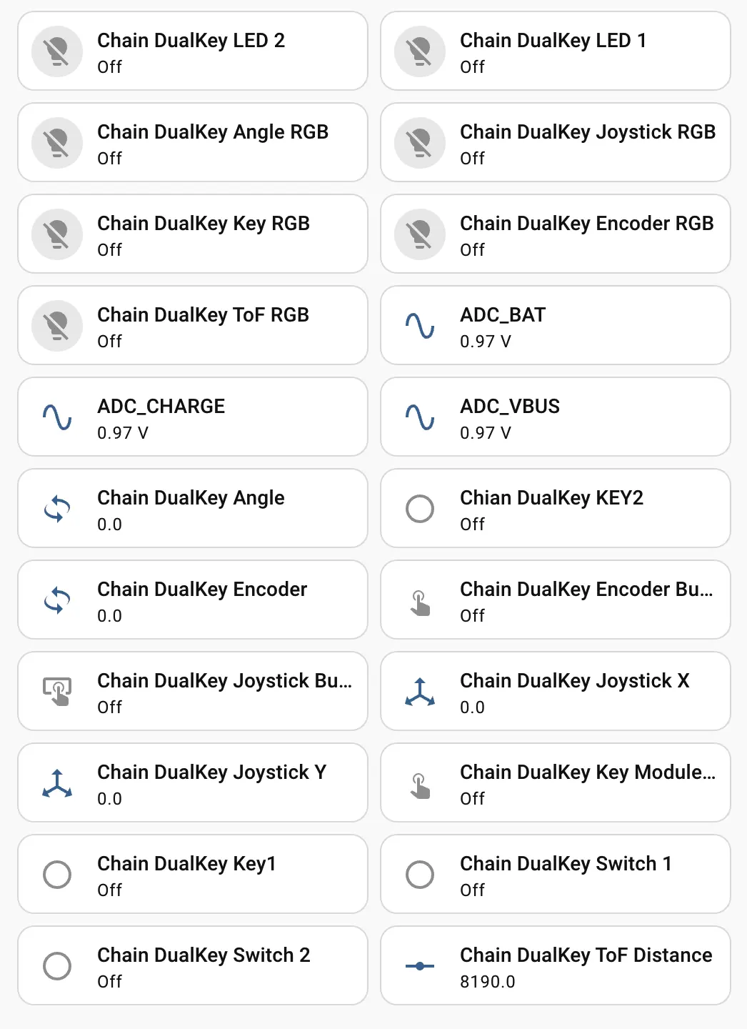
- 最后,将这些实体添加到 Dashboard 中,即可获得如下显示效果。
Page Tools