


Arduino 上手教程
2. 设备开发 & 案例程序
3. M5Unified
4. M5GFX
5. 拓展模块
Unit
Base
Cap
IoT
Station Grove Power 接口电源管理
Station 接口电源管理相关API与案例程序。
USB-A口输出电流计算原理
Station 的 USB-A 口仅支持获取输出电流信息,需要通过 GPIO34 获取 INA199Ax1 的输出电压值进行换算得到 USB-A 输出电流值,此电压值与 USB-A 输出电流值近似成正比。
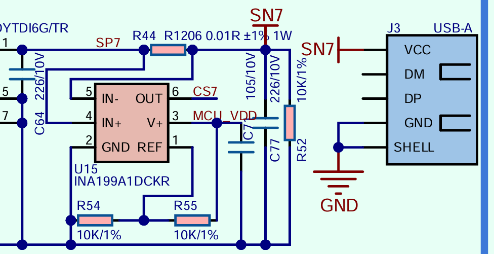
从上方的 Station 原理图中可知,INA199x1 的基准电压(REF)理想值为:(R54\(R54+R55))MCU_VDD ,即 1\2MCU_VDD 。但由于硬件器件可容偏差及本设计结构非精准结构,此基准电压(REF)实际值需要实际测量。
查阅 INA199 数据手册可知,其通过检测分流电阻(即上图中的 R44 )两端的电压差来测量电流,然后根据内部设定的增益(INA199x1 为 50V/V),将实时检测到的电流信号转换为相应的模拟电压信号从 OUT 引脚输出(即下方代码中的 usb_vol)。当 USB-A 口空载时,INA199x1 的输出电压值接近基准电压(REF)实际值,即下方代码中的 usb_vref 。OUT 引脚输出电压计算公式为 usb_vol = usb_vref + Io * (R44*50),换算后 Io = (usb_vol - usb_vref) \ (R44*50) 。
具体实现请见下方代码。
案例程序
cpp
1 2 3 4 5 6 7 8 9 10 11 12 13 14 15 16 17 18 19 20 21 22 23 24 25 26 27 28 29 30 31 32 33 34 35 36 37 38 39 40 41 42 43 44 45 46 47 48 49 50 51 52 53 54 55 56 57 58 59 60 61 62 63 64 65 66 67 68
#include <Arduino.h>
#include "M5Unified.h"
#define USB_PIN 34
const float V_REF = 3.3; // Analog reference voltage (e.g., 5V or 3.3V) due to hardware
const float Res_BITS = 12.0; // ADC resolution (bits)
const float ADC_STEPS = (1 << int(Res_BITS)) - 1; // Number of steps (2^Res_BITS - 1)
float usb_vref;//INA199x1 REF
float get_USB_Volt(float num){
float volt;
for (size_t i = 0; i < num; i++) {
volt = volt + analogRead(USB_PIN);
delay(10);
}
volt = volt / num / ADC_STEPS * V_REF;
return volt;//unit: V
}
void setup()
{
auto cfg = M5.config();
M5.begin(cfg);
M5.Display.setTextDatum(middle_center);
M5.Display.setTextColor(TFT_BLACK);
M5.Display.setTextFont(&fonts::FreeSansOblique9pt7b);
M5.Display.setTextSize(1);
M5.Power.setExtOutput(false, (m5::ext_port_mask_t)(m5::ext_USB|m5::ext_PA|m5::ext_PB1|m5::ext_PB2|m5::ext_PC1|m5::ext_PC2));
analogReadResolution(12);//Set ADC Resolution
analogSetAttenuation(ADC_11db);//Set ADC Attenuation
M5.Lcd.clear(TFT_WHITE);
M5.Power.setExtOutput(true, (m5::ext_port_mask_t)(m5::ext_USB|m5::ext_PA|m5::ext_PB1|m5::ext_PB2|m5::ext_PC1|m5::ext_PC2));
delay(200);
usb_vref = get_USB_Volt(5);//Obtain the output voltage of INA199 when the USB is in a no-laod state. This voltage is the reference voltage.
}
void loop()
{
M5.Display.clear(TFT_WHITE);
bool isSupplying = M5.Power.getExtOutput();
if(isSupplying){
M5.Lcd.setCursor(0, 10);
float usb_vol = get_USB_Volt(5);//Obtain the real-time output voltage of INA199
float usb_current = ((usb_vol - usb_vref) / 50.0f / 0.01f * 1000.0f);//unit:mA usb_vol = usb_vref + Io(unit: A)*(0.01Ω*50)
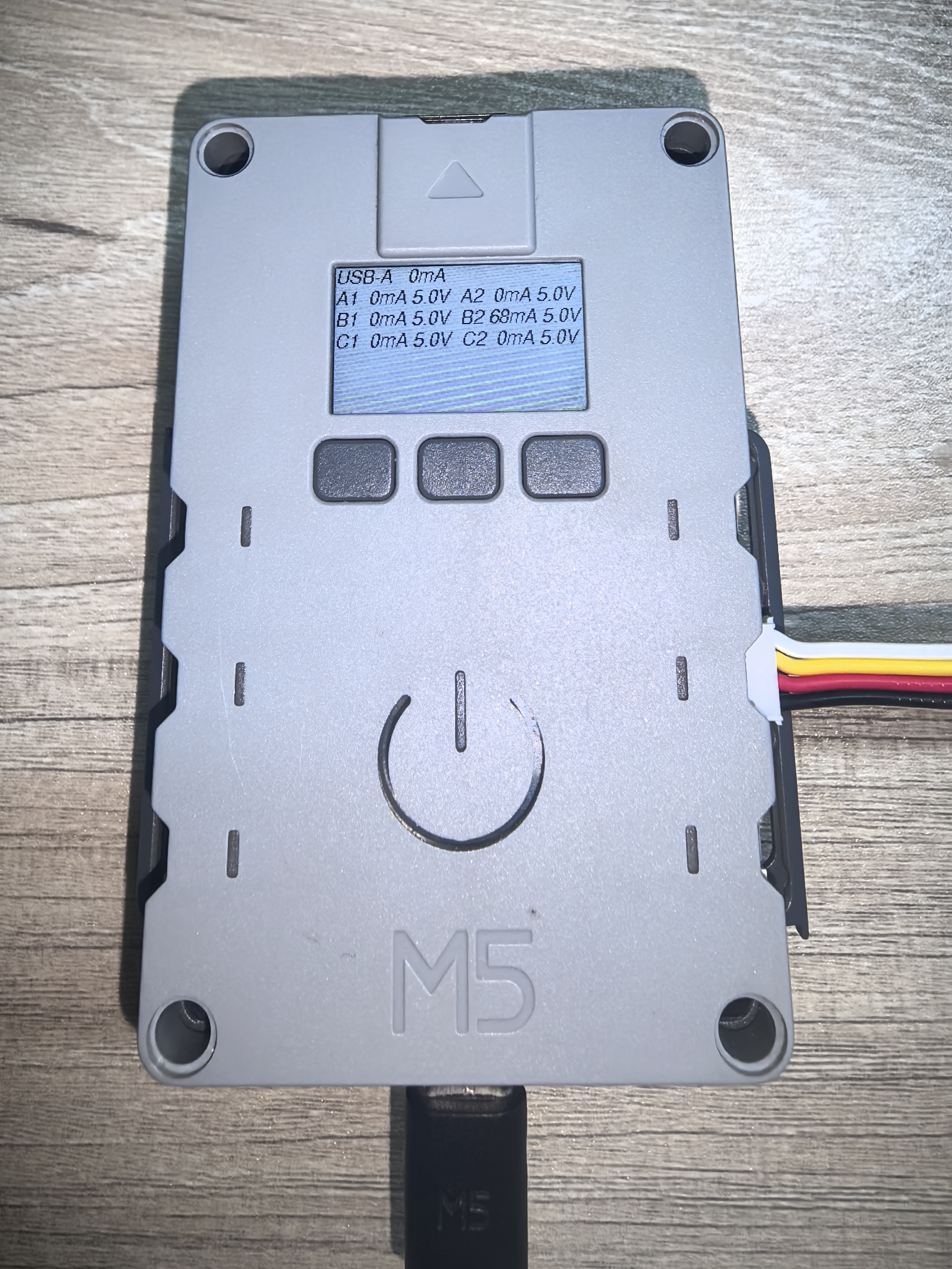
M5.Lcd.printf("USB-A %3.0fmA", usb_current);
M5.Lcd.setCursor(0, 30);
M5.Lcd.printf("A1%3.0fmA %1.1fV A2%3.0fmA %1.1fV\n",
M5.Power.Ina3221[0].getCurrent(0) * 1000,
M5.Power.Ina3221[0].getBusVoltage(0),
M5.Power.Ina3221[0].getCurrent(1) * 1000,
M5.Power.Ina3221[0].getBusVoltage(1));
M5.Lcd.setCursor(0, 50);
M5.Lcd.printf("B1%3.0fmA %1.1fV B2%3.0fmA %1.1fV\n",
M5.Power.Ina3221[0].getCurrent(2) * 1000,
M5.Power.Ina3221[0].getBusVoltage(2),
M5.Power.Ina3221[1].getCurrent(0) * 1000,
M5.Power.Ina3221[1].getBusVoltage(0));
M5.Lcd.setCursor(0, 70);
M5.Lcd.printf("C1%3.0fmA %1.1fV C2%3.0fmA %1.1fV\n",
M5.Power.Ina3221[1].getCurrent(1) * 1000,
M5.Power.Ina3221[1].getBusVoltage(1),
M5.Power.Ina3221[1].getCurrent(2) * 1000,
M5.Power.Ina3221[1].getBusVoltage(2));
}
delay(1000);
} 该程序将在屏幕上显示各 Grove 实时的输出电压电流信息。
API
Station 接口电源管理部分使用了M5Unified库中的Power_Class, 更多相关的API可以参考下方文档: