Arduino Quick Start
2. Devices & Examples
3. M5Unified
4. M5GFX
5. Extensions
Unit
Atomic
Base
Tab5
IoT
Accessories
Atomic RS485/232 Base Arduino Tutorial
1. Preparation
Environment Configuration: Refer to the Arduino IDE Quick Start Tutorial to complete the IDE installation, and install the corresponding board management for the development board you are using, as well as the required driver libraries.
Driver libraries used:
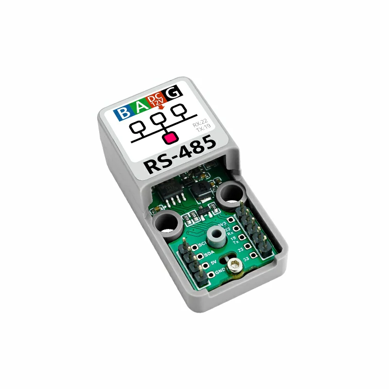
Hardware products used:
2. RS485/232 Communication Overview
- RS485 and RS232 are two common serial communication protocols widely used in industrial automation, embedded systems, and other fields. RS485 supports multi-point communication and is suitable for long-distance transmission, while RS232 is typically used for point-to-point communication, ideal for short-distance connections.
2.1 RS485 Communication Introduction
1. Core Definition:
- A physical layer interface standard that defines electrical characteristics (such as voltage and impedance) and connection methods.
- Supports half-duplex communication, requiring enable signals to control data sending and receiving, with no need for a separate transmit/receive clock line.
2. Key Features:
- Communication distance: Up to 1200 meters without repeaters.
- Transmission rate: Inversely proportional to distance, up to 10Mbps within 10 meters, about 100Kbps at 1200 meters.
- Node capacity: A single bus can connect up to 32 devices (extendable to over 256 through repeaters).
- Anti-interference: Uses differential transmission (two signal lines A/B with the signal as their voltage difference), effectively resisting common-mode interference.
3. Working Principle:
- Voltage levels: Logic “1” corresponds to A-B ≥ 200mV, Logic “0” corresponds to A-B ≤ -200mV.
- Transmitter: Converts TTL levels to differential signals for transmission over A line (positive) and B line (negative).
- Receiver: Receives A/B differential signals and converts them back to TTL levels for device processing.
- Interface form: No fixed interface, mostly two-wire terminals or DB9 (9-pin), only A and B wires are required for communication.
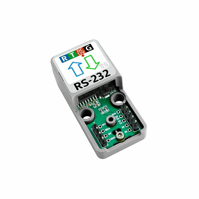
2.2 RS232 Communication Introduction
1. Core Definition:
- An electrical interface standard for asynchronous serial communication, specifying signal levels, pin functions, and interface formats.
- Supports full-duplex communication, with dedicated transmit (TXD) and receive (RXD) lines, allowing simultaneous sending and receiving without enable signal control.
2. Key Features:
- Communication distance: The standard specifies a maximum of 15 meters; in practice, usually within 1.5 meters to ensure signal quality.
- Transmission rate: Inversely proportional to distance, up to 20Kbps.
- Node capacity: Point-to-point communication, only two devices can be connected directly.
- Anti-interference: Uses single-ended transmission (referenced to ground), less resistant to interference, easily affected by common-mode noise.
3. Working Principle:
- Voltage levels: Logic “1” corresponds to -3V to -15V, Logic “0” corresponds to +3V to +15V.
- Transmitter: Converts TTL levels to RS232 levels and sends data via the TXD line.
- Receiver: Receives RS232 level signals via the RXD line and converts them back to TTL levels for device processing.
- Interface form: Common DB9 (9-pin) or DB25 (25-pin) connectors, only TXD, RXD, and GND wires are required for communication.
3. Example
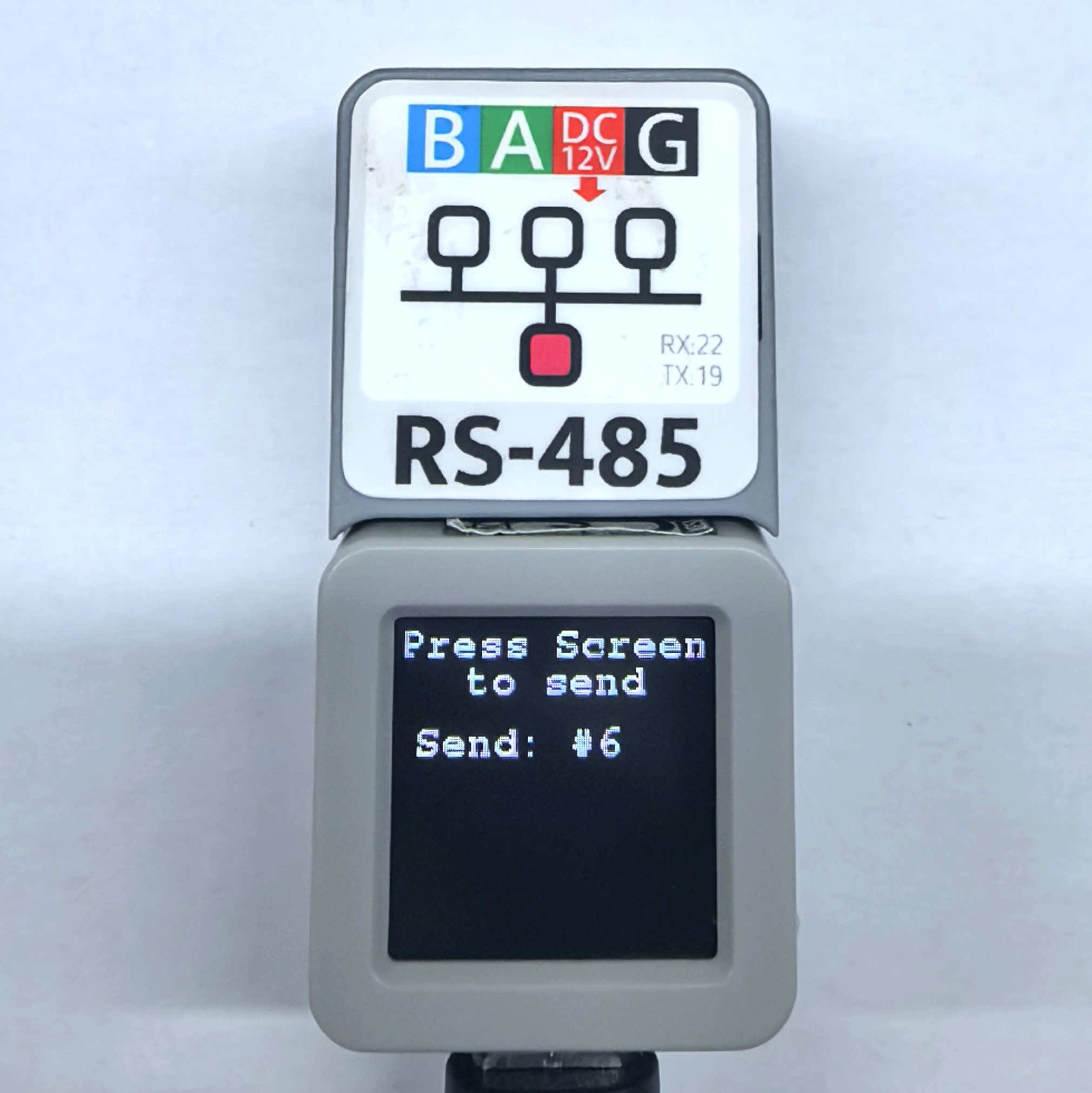
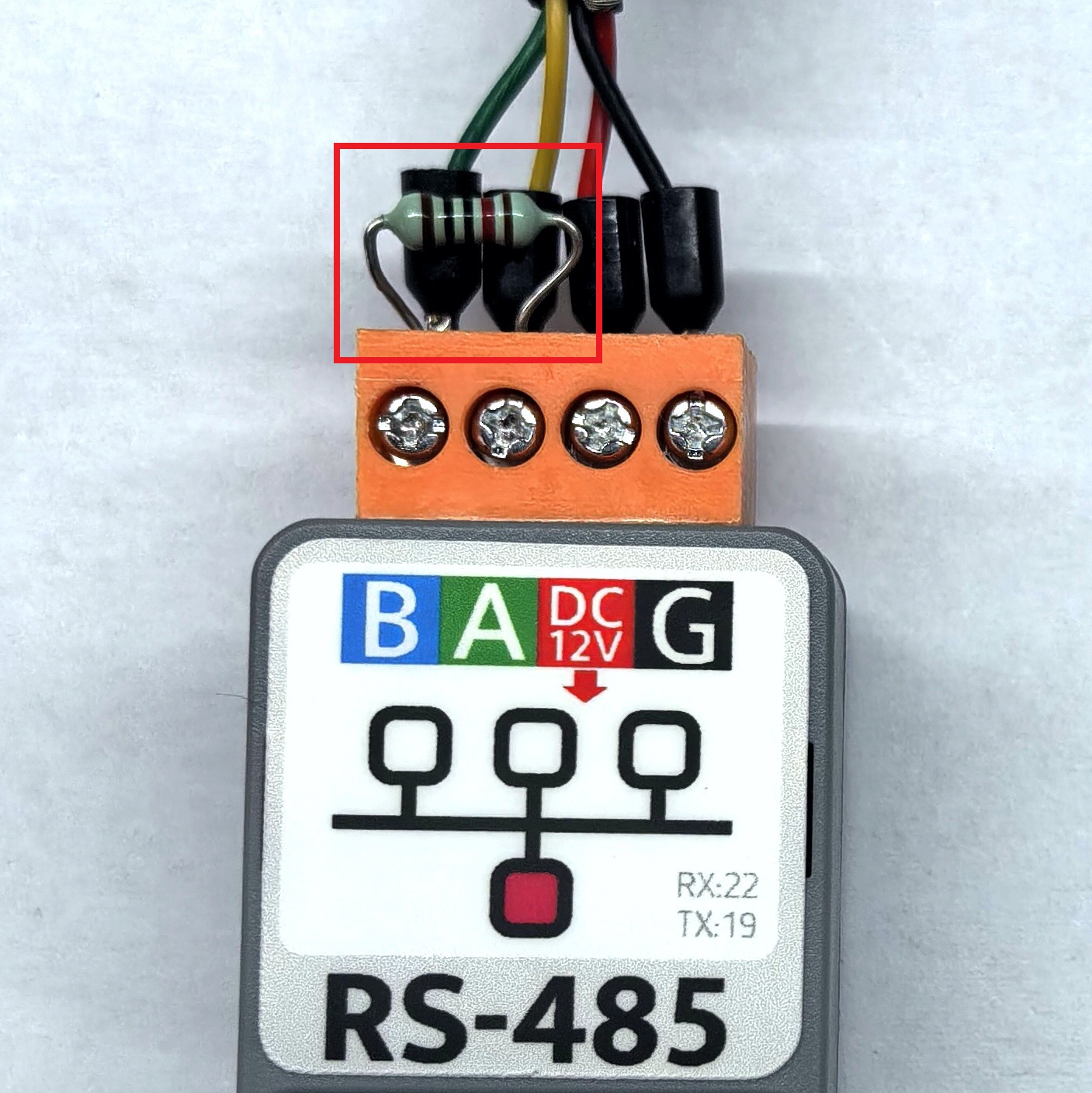
In this tutorial, the main control device used is AtomS3R, paired with the Atomic RS485/232 Base. This module communicates via Serial. Modify the pin definitions in the program according to the actual circuit connection. After the device is connected, the corresponding serial pins are
G5 (RX)andG6 (TX).Atomic RS485 Base does not have an integrated 120Ω terminal resistor inside. You can refer to the position in the diagram below to add a 120Ω resistor between the A/B lines.
#include <M5Unified.h>
#include <M5GFX.h>

static int cnt = 0;          // Counter for RS485 sent messages (increments per transmission)
String recvBuffer;           // Buffer to store received RS485 data

void setup() {
    M5.begin();
    M5.Display.clear();
    M5.Display.setFont(&fonts::FreeMonoBold9pt7b);
    M5.Display.drawString("Send :", 0, 5);
    M5.Display.drawString("Receive :", 0, 50);

    Serial.begin(115200);

    // Parameters: baud rate=115200, config=8N1 (8 data bits, 1 stop bit, no parity), RX pin=27, TX pin=19
    Serial2.begin(115200, SERIAL_8N1, 5, 6);
}

void loop() {
    M5.update();

    // --- Send Data ---
    String msg = "RS485 #" + String(++cnt);
    Serial2.println(msg);
    Serial.printf("Send: %s\n", msg.c_str());

    // Display sent message on screen
    M5.Display.fillRect(0, 25, 128, 20, TFT_BLACK);
    M5.Display.setTextColor(GREEN);
    M5.Display.setCursor(0, 25);
    M5.Display.printf("%s\n", msg.c_str());

    // --- Receive Data ---
    recvBuffer = "";
    while (Serial2.available()) {
        char ch = Serial2.read();
        recvBuffer += ch;
    }

    // If valid data is received
    if (recvBuffer.length() > 0) {
        Serial.print("Recv: ");
        Serial.print(recvBuffer);
        Serial2.flush();

        // Display received message on screen
        M5.Display.setTextColor(YELLOW);
        M5.Display.fillRect(0, 70, 128, 20, TFT_BLACK);
        M5.Display.setCursor(0, 70);
        M5.Display.printf("%s", recvBuffer.c_str());
    }

    delay(2000);
}4. Compile and Upload
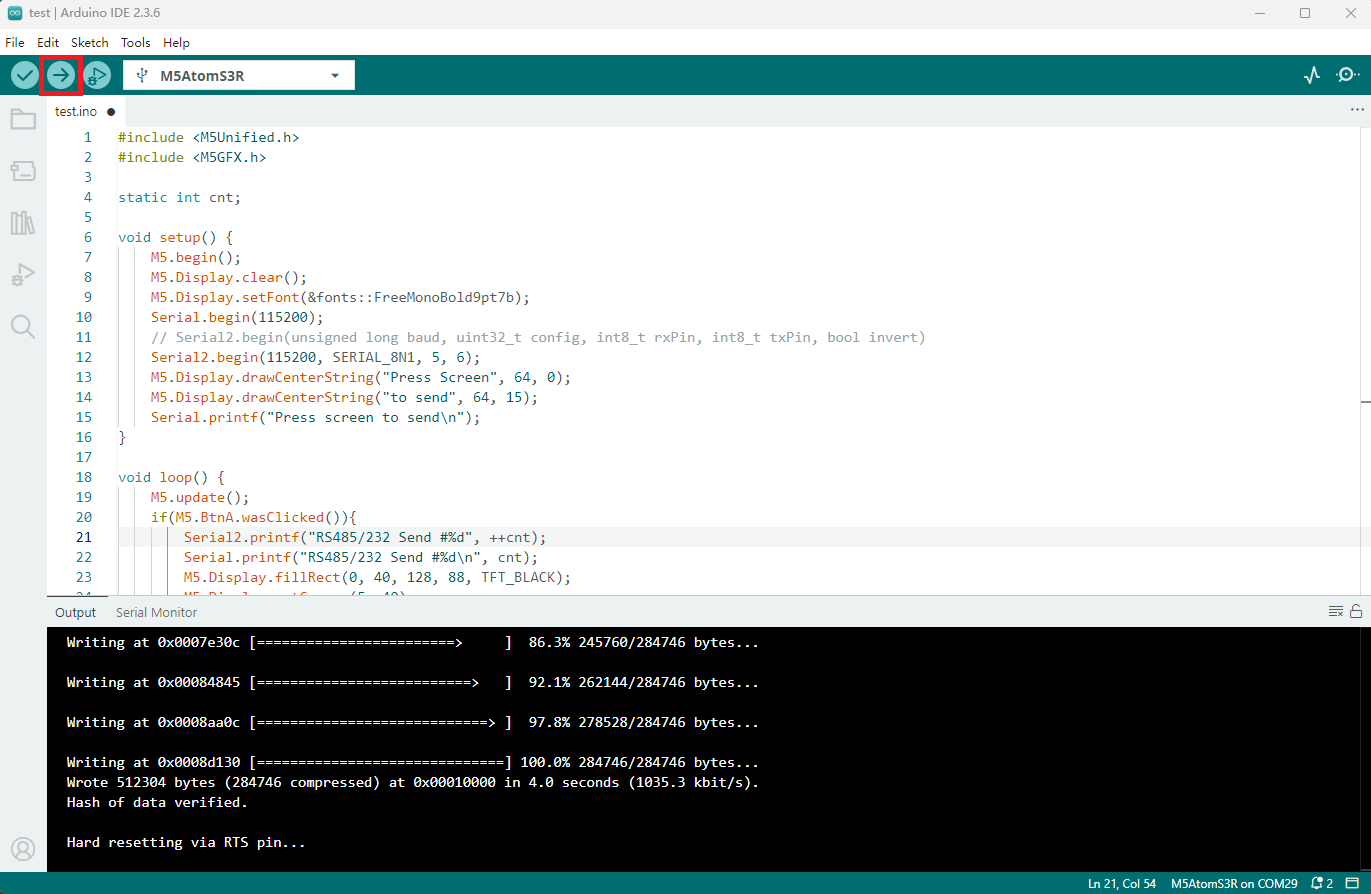
1. Download Mode: Before flashing the program on different devices, you need to enter download mode. This step may vary depending on the main control device. For details, refer to the list of device program download tutorials at the bottom of the Arduino IDE Quick Start Tutorial page to see the specific operation method.
For AtomS3R, press and hold the reset button (for about 2 seconds) until the internal green LED lights up, then release. At this point, the device has entered download mode and is ready for flashing.
- 2. Select the device port, click the Compile and Upload button in the upper left of Arduino IDE, and wait for the program to complete compilation and upload to the device.
5. Example Effect Demonstration
- After the above example is successfully downloaded, the device will display the transmitted and received data on the screen when powered on. Every 2 seconds, information is sent through the RS485/232 interface, while the program listens for data received via the same interface. The display effect on the main control screen is shown as follows: