

Arduino Quick Start
2. Devices & Examples
3. M5Unified
4. M5GFX
5. Extensions
Unit
Atomic
Tab5
IoT
Accessories
Station Grove Power
Station Grove power management related APIs and example.
The Calculation Principle of USB-A Output Current
The USB-A port of Station only supports acquiring output current information. It is necessary to obtain the output voltage value of INA199Ax1 through GPIO34 and convert it to get the USB-A output current value, which is approximately proportional to the USB-A output current value.
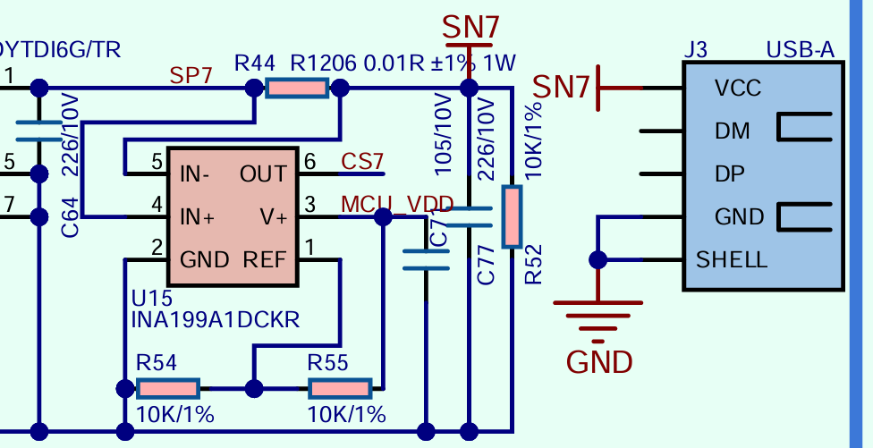
As can be seen from the Station schematic diagram above, the ideal value of the reference voltage (REF) for INA199x1 is: (R54/(R54+R55))MCU_VDD, that is, 1/2 MCU_VDD. However, due to the tolerance of hardware components and the non-precise structure of this design, the actual value of this reference voltage (REF) needs to be measured in practice.
Consulting the INA199 Datasheet, it is known that INA199 measures current by detecting the voltage difference across the shunt resistor (i.e., R44 in the diagram above), and then converts the real-time detected current signal into a corresponding analog voltage signal at the OUT pin (i.e., usb_vol in the code below) according to the internally set gain ( 50V/V for INA199x1 ). When the USB-A port is no-load, the output voltage of INA199x1 is close to the actual value of the reference voltage (REF), i.e., usb_vref in the code below. The output voltage formula for the OUT pin is usb_vol = usb_vref + Io * (R44*50), and after conversion, Io = (usb_vol - usb_vref) \ (R44*50).
For the specific implementation, please refer to the code below.
Example
#include <Arduino.h>
#include "M5Unified.h"
#define USB_PIN 34
const float V_REF = 3.3; // Analog reference voltage (e.g., 5V or 3.3V) due to hardware
const float Res_BITS = 12.0; // ADC resolution (bits)
const float ADC_STEPS = (1 << int(Res_BITS)) - 1; // Number of steps (2^Res_BITS - 1)
float usb_vref;//INA199x1 REF
float get_USB_Volt(float num){
float volt;
for (size_t i = 0; i < num; i++) {
volt = volt + analogRead(USB_PIN);
delay(10);
}
volt = volt / num / ADC_STEPS * V_REF;
return volt;//unit: V
}
void setup()
{
auto cfg = M5.config();
M5.begin(cfg);
M5.Display.setTextDatum(middle_center);
M5.Display.setTextColor(TFT_BLACK);
M5.Display.setTextFont(&fonts::FreeSansOblique9pt7b);
M5.Display.setTextSize(1);
M5.Power.setExtOutput(false, (m5::ext_port_mask_t)(m5::ext_USB|m5::ext_PA|m5::ext_PB1|m5::ext_PB2|m5::ext_PC1|m5::ext_PC2));
analogReadResolution(12);//Set ADC Resolution
analogSetAttenuation(ADC_11db);//Set ADC Attenuation
M5.Lcd.clear(TFT_WHITE);
M5.Power.setExtOutput(true, (m5::ext_port_mask_t)(m5::ext_USB|m5::ext_PA|m5::ext_PB1|m5::ext_PB2|m5::ext_PC1|m5::ext_PC2));
delay(200);
usb_vref = get_USB_Volt(5);//Obtain the output voltage of INA199 when the USB is in a no-laod state. This voltage is the reference voltage.
}
void loop()
{
M5.Display.clear(TFT_WHITE);
bool isSupplying = M5.Power.getExtOutput();
if(isSupplying){
M5.Lcd.setCursor(0, 10);
float usb_vol = get_USB_Volt(5);//Obtain the real-time output voltage of INA199
float usb_current = ((usb_vol - usb_vref) / 50.0f / 0.01f * 1000.0f);//unit:mA usb_vol = usb_vref + Io(unit: A)*(0.01Ω*50)
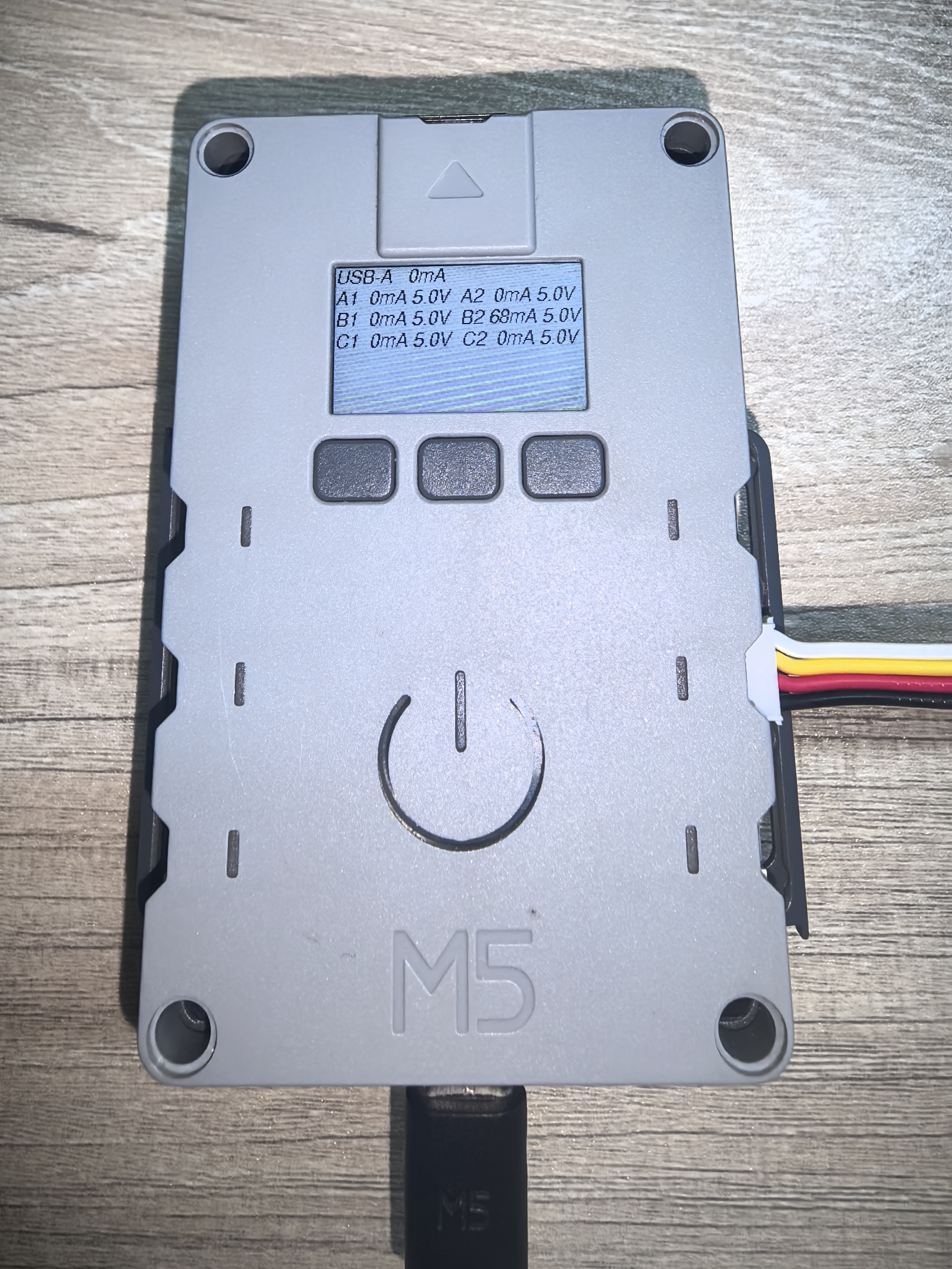
M5.Lcd.printf("USB-A %3.0fmA", usb_current);
M5.Lcd.setCursor(0, 30);
M5.Lcd.printf("A1%3.0fmA %1.1fV A2%3.0fmA %1.1fV\n",
M5.Power.Ina3221[0].getCurrent(0) * 1000,
M5.Power.Ina3221[0].getBusVoltage(0),
M5.Power.Ina3221[0].getCurrent(1) * 1000,
M5.Power.Ina3221[0].getBusVoltage(1));
M5.Lcd.setCursor(0, 50);
M5.Lcd.printf("B1%3.0fmA %1.1fV B2%3.0fmA %1.1fV\n",
M5.Power.Ina3221[0].getCurrent(2) * 1000,
M5.Power.Ina3221[0].getBusVoltage(2),
M5.Power.Ina3221[1].getCurrent(0) * 1000,
M5.Power.Ina3221[1].getBusVoltage(0));
M5.Lcd.setCursor(0, 70);
M5.Lcd.printf("C1%3.0fmA %1.1fV C2%3.0fmA %1.1fV\n",
M5.Power.Ina3221[1].getCurrent(1) * 1000,
M5.Power.Ina3221[1].getBusVoltage(1),
M5.Power.Ina3221[1].getCurrent(2) * 1000,
M5.Power.Ina3221[1].getBusVoltage(2));
}
delay(1000);
} The program will display the real-time output voltage and current information of each Grove on the screen.
API
Station Grove power section uses the Power_Class from the M5Unified library. For more related APIs, please refer to the documentation below: