Arduino Quick Start
2. Devices & Examples
StackChan
3. M5Unified
4. M5GFX
5. Extensions
Unit
Atomic
Base
IoT
Accessories
Module LoRa868 v1.2 Arduino Usage Tutorial
1. Preparation
- Environment Setup: Refer to the Arduino IDE Quick Start Guide to install the IDE, then install the appropriate board definition and required driver libraries for your development board.
- Required Libraries:
- Hardware Used:

2. Example
Example Description
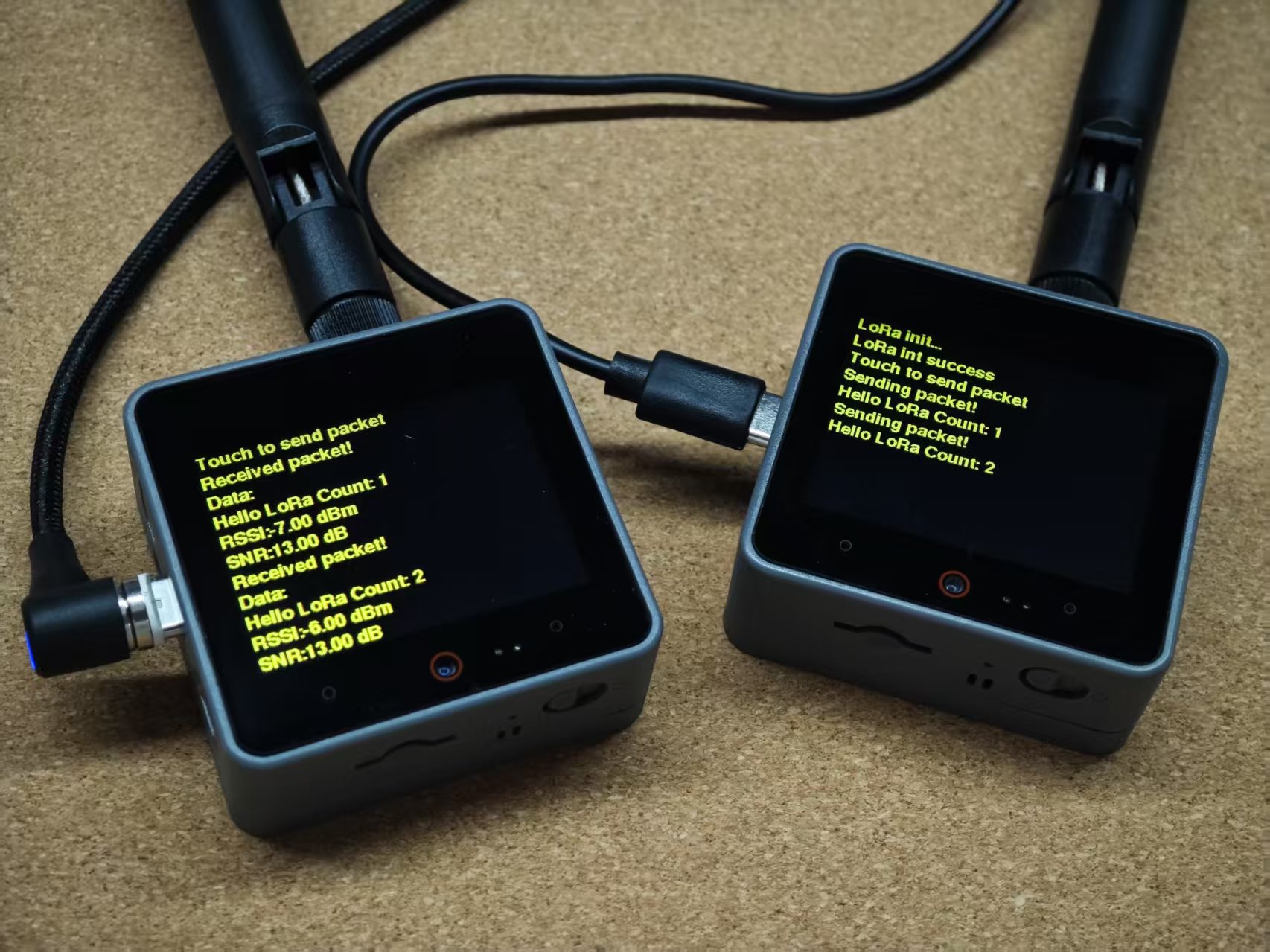
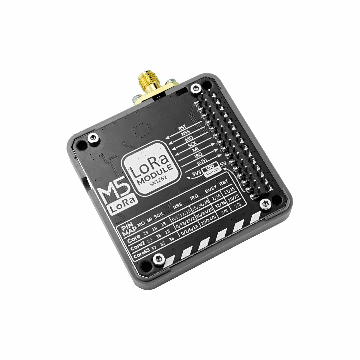
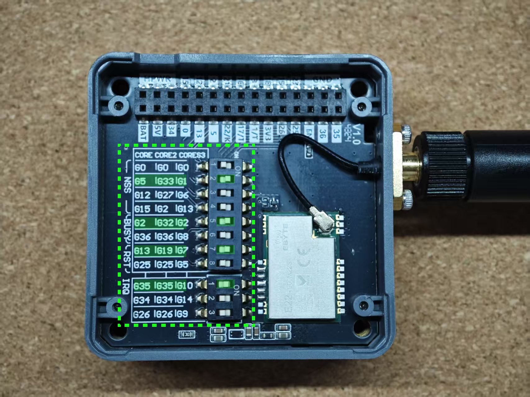
This example uses two Module LoRa868 v1.2 modules with two CoreS3 controllers. Load the same LoRa transmit/receive test sketch onto each to perform point-to-point data communication. When using other host boards, configure the corresponding I/O pin assignments in the code according to your wiring. The Module LoRa868 v1.2 also features DIP switches on its bottom for flexible pin mapping, allowing compatibility with various host devices as needed.
cpp
1 2 3 4 5 6 7 8 9 10 11 12 13 14 15 16 17 18 19 20 21 22 23 24 25 26 27 28 29 30 31 32 33 34 35 36 37 38 39 40 41 42 43 44 45 46 47 48 49 50 51 52 53 54 55 56 57 58 59 60 61 62 63 64 65 66 67 68 69 70 71 72 73 74 75 76 77 78 79 80 81 82 83 84 85 86 87 88 89 90 91 92 93 94 95 96 97 98 99 100 101 102 103 104 105 106 107 108 109 110 111 112 113 114 115 116 117 118 119 120 121 122 123 124 125 126 127 128 129 130 131 132 133 134 135 136 137 138 139 140 141 142 143 144 145 146 147 148
#include <Arduino.h>
#include <M5GFX.h>
#include <M5Unified.h>
#include <RadioLib.h>
#include "freertos/FreeRTOS.h"
#include "freertos/task.h"

#define LORA_BW 500.0
#define LORA_SF 7
#define LORA_CR 8

#define LORA_FREQ         868.0
#define LORA_SYNC_WORD    0x34
#define LORA_TX_POWER     22
#define LORA_PREAMBLE_LEN 20

#define CONFIG_MISO_GPIO GPIO_NUM_35
#define CONFIG_MOSI_GPIO GPIO_NUM_37
#define CONFIG_SCLK_GPIO GPIO_NUM_36

#define CONFIG_LORA_NSS  GPIO_NUM_1
#define CONFIG_LORA_BUSY GPIO_NUM_2
#define CONFIG_LORA_RST  GPIO_NUM_7
#define CONFIG_LORA_IRQ  GPIO_NUM_10

SX1262 *radio = NULL;

// save transmission states between loops
int transmissionState = RADIOLIB_ERR_NONE;

// flag to indicate transmission or reception state
bool transmitFlag = false;

volatile bool operationDone = false;

ICACHE_RAM_ATTR void setFlag(void)
{
    // we sent or received a packet, set the flag
    operationDone = true;
}

void lora_init()
{
    radio = new SX1262(new Module(CONFIG_LORA_NSS,     // NSS
                                  CONFIG_LORA_IRQ,     // DIO1
                                  CONFIG_LORA_RST,     // RST
                                  CONFIG_LORA_BUSY));  // BUSY

    M5.Display.println("LoRa init...");

    //   RADIOLIB_ERR_NONE
    int state = radio->begin(LORA_FREQ, LORA_BW, LORA_SF, LORA_CR, LORA_SYNC_WORD, LORA_TX_POWER, LORA_PREAMBLE_LEN,
                             3.0, false);

    radio->setDio1Action(setFlag);

    Serial.print(F("Starting to listen ... "));
    state = radio->startReceive();
    if (state == RADIOLIB_ERR_NONE) {
        Serial.println(F("success!"));
        M5.Display.println("LoRa init success");
        M5.Display.println("Touch to send packet");
    } else {
        Serial.print(F("failed, code "));
        M5.Display.println("LoRa init failed");
        Serial.println(state);
        while (true) {
            delay(10);
        }
    }
}

void setup()
{
    M5.begin();
    Serial.begin(115200);
    M5.Display.setTextColor(YELLOW);
    M5.Display.setFont(&fonts::FreeSansBold9pt7b);
    M5.Display.setTextScroll(true);
    lora_init();
}

int msg_count = 0;
String tx_payload;
String rx_payload;
void loop()
{
    M5.update();
    auto t = M5.Touch.getDetail();

    if (t.wasClicked() || M5.BtnA.wasClicked()) {
        // send another one
        msg_count++;
        Serial.print(F("Sending another packet ... "));

        tx_payload = "Hello LoRa Count: " + String(msg_count);
        transmissionState = radio->transmit(tx_payload);
        M5.Display.println("Sending packet!");
        M5.Display.println(tx_payload);
        transmitFlag = true;
    }
    // check if the previous operation finished
    if (operationDone) {
        // reset flag
        operationDone = false;
        if (transmitFlag) {
            transmitFlag = false;
            int state    = radio->startReceive();
        } else {
            int state = radio->readData(rx_payload);
            Serial.println("lora_rx_flag");
            Serial.println(state);
            if (state == RADIOLIB_ERR_NONE) {
                // packet was successfully received
                Serial.println(F("Received packet!"));

                // print data of the packet
                Serial.print(F("Data:\t\t"));
                Serial.println(rx_payload);

                // print RSSI (Received Signal Strength Indicator)
                Serial.print(F("RSSI:\t\t"));
                Serial.print(radio->getRSSI());
                Serial.println(F(" dBm"));

                // print packet length
                Serial.print(F("Length:\t\t"));
                Serial.print(radio->getPacketLength());

                // print SNR (Signal-to-Noise Ratio)
                Serial.print(F("SNR:\t\t"));
                Serial.print(radio->getSNR());
                Serial.println(F(" dB"));

                // display on screen
                M5.Display.println("Received packet!");
                M5.Display.println("Data:");
                M5.Display.println(rx_payload);
                M5.Display.print("RSSI:");
                M5.Display.print(radio->getRSSI());
                M5.Display.println(" dBm");
                M5.Display.print("SNR:");
                M5.Display.print(radio->getSNR());
                M5.Display.println(" dB");
            }
        }
    }
}3. Compile & Upload
- Download Mode: Before uploading for different controllers, enter download mode. Procedures vary by host board—see the device-specific download instructions at the bottom of the Arduino IDE Quick Start Guide.
- For CoreS3: Hold down the RESET button for about 2 seconds until the internal green LED lights, then release to enter download mode.
.gif)
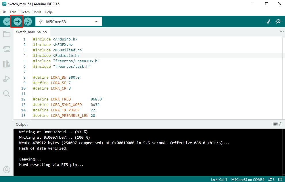
- Select the board’s port, then click the Upload button in the Arduino IDE. Wait for compilation and flashing to complete.
4. LoRa TX/RX Test
After loading the same LoRa test sketch onto both CoreS3 + Module LoRa868 v1.2 setups, touch the screen to send data between devices.