M5StickV MaixPy クイックスタートガイド
ドライバのインストール
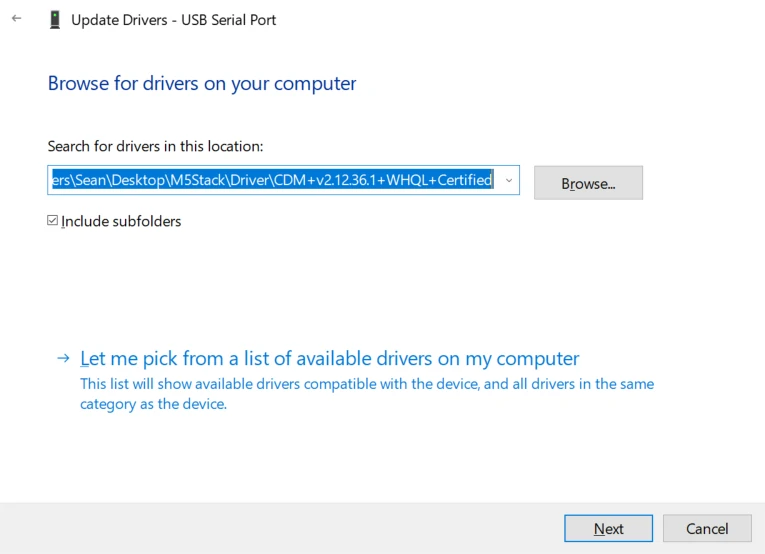
M5Stack または USB Serial です。Windows ユーザーの場合、デバイスマネージャーからドライバファイルを直接指定してインストールする方法を推奨します。実行ファイルによるインストール方式では正常に動作しない場合があります。)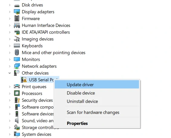
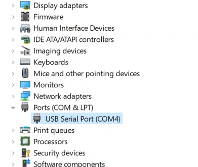
システム環境設定 -> セキュリティとプライバシー -> 一般 -> 以下の場所からダウンロードした App を許可 -> App Store と認証済みの開発者 を選択してください。ファームウェアの書き込み
Kflash_GUI
- ファームウェアおよび Kflash_GUI 書き込みツールをダウンロードします。(UnitV と StickV は同一のファームウェアを使用します)
| ファームウェアバージョン | ダウンロードリンク |
|---|---|
| M5StickV_Firmware_v5.1.2.kfpkg | Download |
| ソフトウェアバージョン | ダウンロードリンク |
|---|---|
| Kflash_GUI_Windows | Download |
| Kflash_GUI_MacOS | Download |
| Kflash_GUI_Linux | Download |
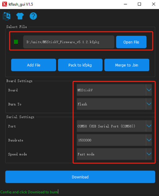
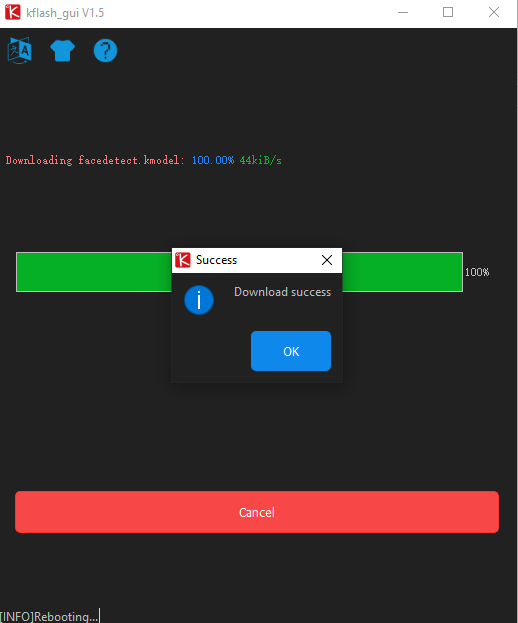
- デバイスを PC に接続し、書き込みツール Kflash_GUI を起動します。対応するデバイスポート、開発ボードタイプ(M5StickV)、ファームウェア、ボーレートを選択してください。「Download」をクリックすると書き込みが開始されます。
MaixPy IDE
MaixPy IDE は、スクリプトのリアルタイム編集・実行、カメラ画像のリアルタイム監視、ファイル転送などを簡単に行えるツールです。初心者や、迅速にプロジェクトを構築したい開発者に適しています。
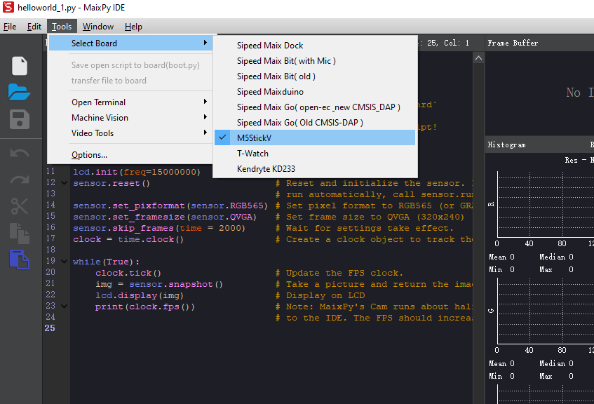
MaixPy IDE を起動し、ツールバーから開発ボードモデルを選択します。Tools-> Select Board-> M5StickV
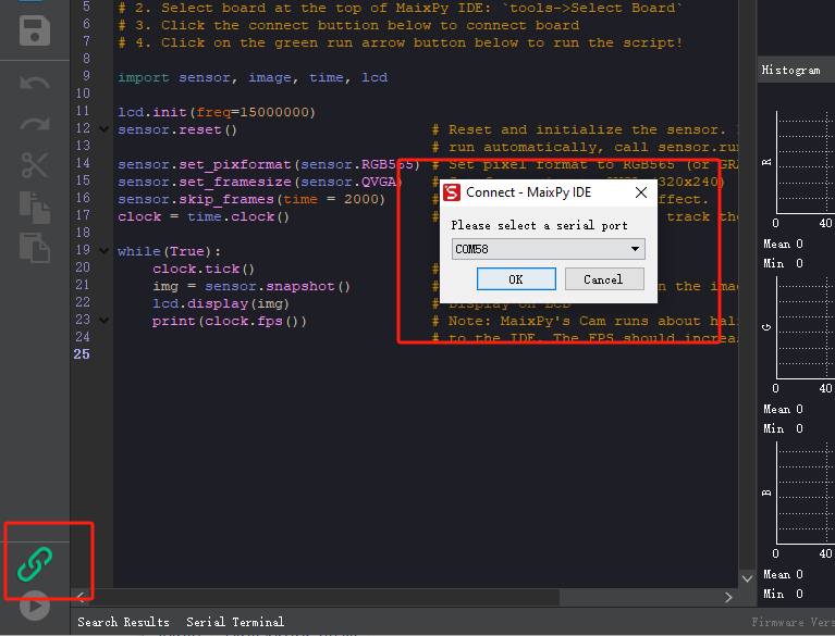
左下の接続ボタンをクリックし、正しい接続ポートを選択して「OK」をクリックします。
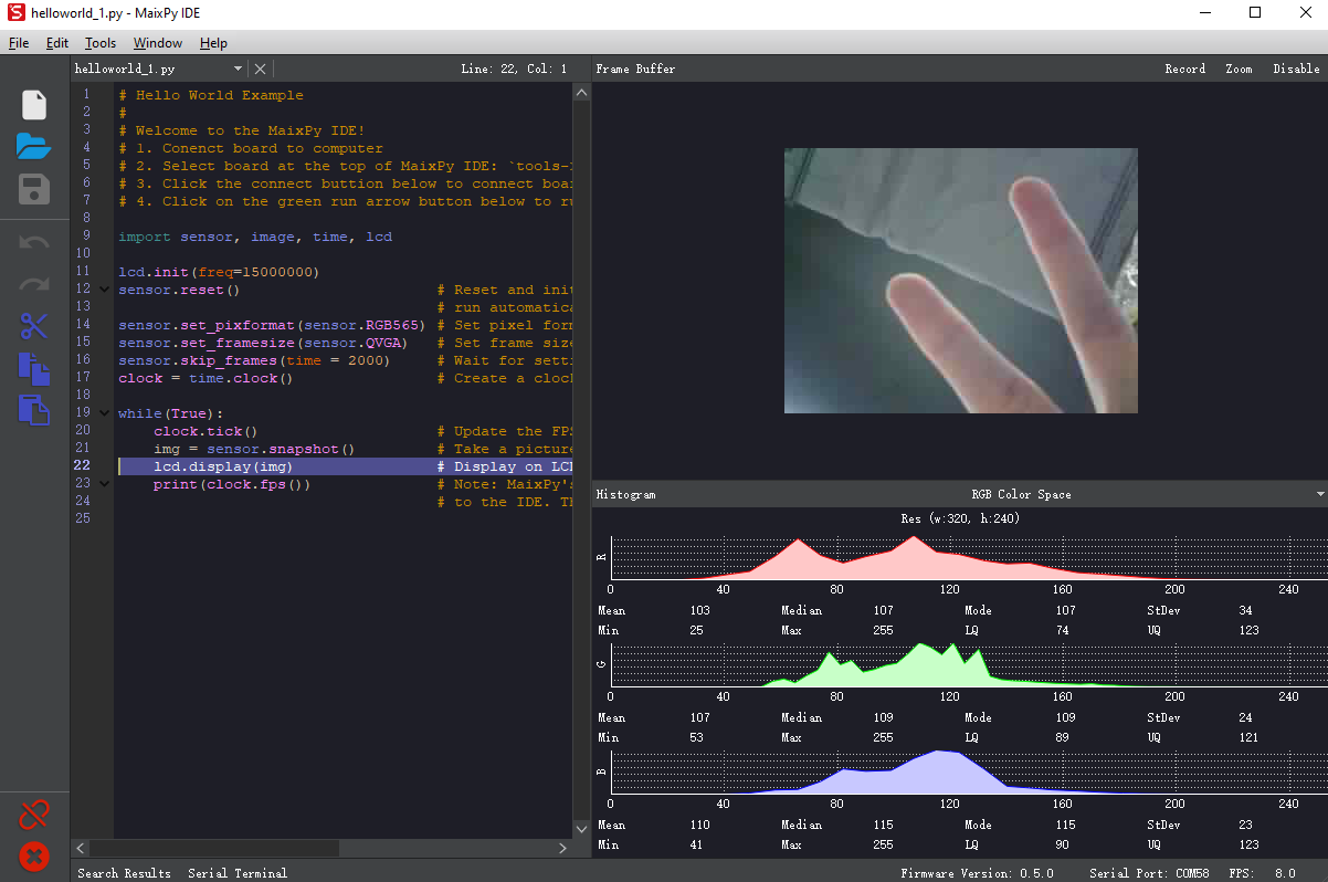
接続ボタンが赤色に変わると接続成功です。上部のテキストエリアでコードを編集し、左下の実行ボタンをクリックして実行できます。
シリアルデバッグツール
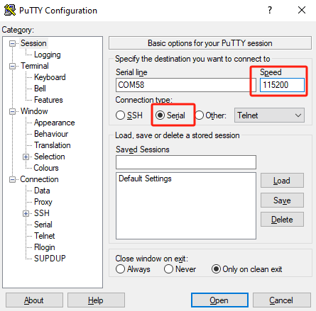
1. デバイスの USB はデフォルトでシステムログポートとして有効になっています。このポートを使用して PC に接続し、任意のターミナルツールでアクセスできます。デフォルトのボーレートは 115200bps です。以下の操作説明は Putty を例にしています。
2. Putty を起動し、デバイスを PC に接続します。Putty で対応するポート番号とボーレートを設定し、「Open」をクリックします。
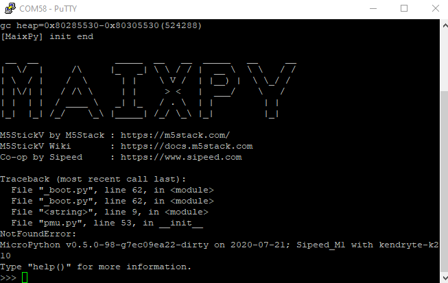
3. 接続が成功すると、自動的に MaixPy の対話型インターフェースに入ります。デバイスはデフォルトプログラムを実行中のため、Ctrl+C を押して実行を中断し、コマンドラインに入ることができます。
ファイルの編集と実行
ファイルの編集
MaixPy には、オープンソースのエディタ Micropython Editor(pye) が内蔵されており、プログラムファイルを簡単に編集できます。
os.listdir() を使用すると、現在のディレクトリ内のファイルを確認できます。
pye("hello.py") を使用すると、ファイルを作成して編集モードに入ります。ショートカットキーなどの使用方法はこちらをご参照ください。
編集完了後、Ctrl+S > Enter で保存し、Ctrl+Q でエディタを終了します。
注意: Backspace キーの代わりに必ず Del キーを使用してください。Backspace キーはデフォルトで Ctrl+H をトリガーします。
プログラムの実行
os.chdir() を使用して作業ディレクトリを切り替えます。例:os.chdir("/flash")
方法一:コマンドラインで Python コードを逐次実行
import hello を実行すると、hello maixpy が出力されます。
注意点として、import は 1 回しか実行されません。複数回実行したい場合は、以下の方法で .py ファイルを実行することを推奨します。
方法二: .py ファイルを実行
exec() 関数を使用して hello.py を実行します。
with open("hello.py") as f:
    exec(f.read())
起動時に自動実行するスクリプト
システムは /flash または /sd ディレクトリに boot.py ファイルを作成し、起動時に自動的に実行します。このファイルを編集することで、起動時に実行するプログラムをカスタマイズできます。
MaixPy IDE
MaixPy IDE は、スクリプトのリアルタイム編集、アップロード、実行、カメラ画像のリアルタイム監視、ファイル転送などを簡単に実現できます。データの圧縮・転送に一定のリソースを消費するため、パフォーマンスはやや低下しますが、高い性能を必要としない場合やデバッグ段階の開発者にとって非常に便利なツールです。
Windows プラットフォームでは、exe ファイルをダブルクリックしてインストーラを実行してください。
Linux の場合、実行権限を付与してから以下のコマンドを実行します。
chmod +x maixpy-ide-linux-x86_64-0.2.2.run
./maixpy-ide-linux-x86_64-0.2.2.run
MaixPy IDE を起動し、ツールバーから開発ボードモデルを選択します。Tool-> Select Board-> M5StickV(ツール -> 開発ボードを選択)

左下の接続ボタンをクリックし、正しい接続ポートを選択して「OK」をクリックします。

接続ボタンが緑色から赤色に変わると、接続成功です。上部のエディタでコードを編集し、左下の実行ボタンをクリックしてコードを実行・検証できます。

WS2812
固件内置了 WS2812 RGB LED 驱动库,以下为参考例程:
from modules import ws2812
from fpioa_manager import *
fm.register(board_info.CONNEXT_A)
class_ws2812 = ws2812(board_info.CONNEXT_A,130)
r=0
dir = True
while True:
    if dir:
        r += 1
    else:
        r -= 1
    if r>=255:
        r = 255
        dir = False
    elif r<0:
        r = 0
        dir = True
    for i in range(130):
        a = class_ws2812.set_led(i,(0,0,r))
a=class_ws2812.display()PMU
説明:この API を使用することで、ボタンの短押しによるリセット、長押しによるスリープを実現できます。True または False を渡します。True でボタン検出を有効化、False で検出を無効化します。
from pmu import axp192
pmu = axp192()
pmu.enablePMICSleepMode(True)
MaixPy サンプルプログラム
Quoted from: https://github.com/anoken/purin\_wo\_motto\_mimamoru\_gijutsu/tree/master/03\_maixpy\_example
Button
example
import lcd
from Maix import I2S, GPIO
from fpioa_manager import fm
from board import board_info

lcd.init()
fm.register(board_info.BUTTON_A, fm.fpioa.GPIO1)
but_a=GPIO(GPIO.GPIO1, GPIO.IN, GPIO.PULL_UP)

fm.register(board_info.BUTTON_B, fm.fpioa.GPIO2)
but_b = GPIO(GPIO.GPIO2, GPIO.IN, GPIO.PULL_UP)

but_a_pressed = 0
but_b_pressed = 0

while(True):
    if but_a.value() == 0 and but_a_pressed == 0:
        print("A_push")
        but_a_pressed=1
    if but_a.value() == 1 and but_a_pressed == 1:
        print("A_release")
        but_a_pressed=0

    if but_b.value() == 0 and but_b_pressed == 0:
        print("B_push")
        but_b_pressed=1
    if but_b.value() == 1 and but_b_pressed == 1:
        print("B_release")
but_b_pressed=0LED
example
from fpioa_manager import *
from Maix import GPIO
from board import board_info

fm.register(board_info.BUTTON_A, fm.fpioa.GPIO1)
but_a=GPIO(GPIO.GPIO1, GPIO.IN, GPIO.PULL_UP)

fm.register(board_info.BUTTON_B, fm.fpioa.GPIO2)
but_b = GPIO(GPIO.GPIO2, GPIO.IN, GPIO.PULL_UP)

fm.register(board_info.LED_W, fm.fpioa.GPIO3)
led_w = GPIO(GPIO.GPIO3, GPIO.OUT)
led_w.value(1) # LED is Active Low

fm.register(board_info.LED_R, fm.fpioa.GPIO4)
led_r = GPIO(GPIO.GPIO4, GPIO.OUT)
led_r.value(1) # LED is Active Low

fm.register(board_info.LED_G, fm.fpioa.GPIO5)
led_g = GPIO(GPIO.GPIO5, GPIO.OUT)
led_g.value(1) # LED is Active Low

fm.register(board_info.LED_B, fm.fpioa.GPIO6)
led_b = GPIO(GPIO.GPIO6, GPIO.OUT)
led_b.value(1) # LED is Active Low

lcd.init()
while(True):
    if but_a.value() == 0:
        led_w.value(0)
        led_r.value(1)
        led_g.value(1)
        led_b.value(1)

    elif but_b.value()== 0:
        led_w.value(1)
        led_r.value(0)
        led_g.value(1)
        led_b.value(1)

    else:
        led_w.value(1)
        led_r.value(1)
        led_g.value(1)
led_b.value(1)PWM
example
import time,math
from machine import Timer,PWM
from fpioa_manager import fm
from board import board_info

tim = Timer(Timer.TIMER0, Timer.CHANNEL0, mode=Timer.MODE_PWM)
PWM_ch = PWM(tim, freq=500000, duty=0, pin=board_info.LED_W)
cnt=0
while(True):
    duty_val=math.fabs(math.sin(cnt))*100
    PWM_ch.duty(duty_val)
    cnt=cnt+0.01
time.sleep_ms(10)I2C scan
example
from machine import I2C
i2c = I2C(I2C.I2C0, freq=100000, scl=28, sda=29)
devices = i2c.scan()
print(devices)MPU6886
example
from machine import I2C
import lcd
MPU6886_ADDRESS=0x68
MPU6886_WHOAMI=0x75
MPU6886_ACCEL_INTEL_CTRL=  0x69
MPU6886_SMPLRT_DIV=0x19
MPU6886_INT_PIN_CFG=   0x37
MPU6886_INT_ENABLE=0x38
MPU6886_ACCEL_XOUT_H=  0x3B
MPU6886_TEMP_OUT_H=0x41
MPU6886_GYRO_XOUT_H=   0x43
MPU6886_USER_CTRL= 0x6A
MPU6886_PWR_MGMT_1=0x6B
MPU6886_PWR_MGMT_2=0x6C
MPU6886_CONFIG=0x1A
MPU6886_GYRO_CONFIG=   0x1B
MPU6886_ACCEL_CONFIG=  0x1C
MPU6886_ACCEL_CONFIG2= 0x1D
MPU6886_FIFO_EN=   0x23

i2c = I2C(I2C.I2C0, freq=100000, scl=28, sda=29)
devices = i2c.scan()
time.sleep_ms(10)
print("i2c",devices)

def write_i2c(address, value):
    i2c.writeto_mem(MPU6886_ADDRESS, address, bytearray([value]))
    time.sleep_ms(10)

def MPU6866_init():
    write_i2c(MPU6886_PWR_MGMT_1, 0x00)
    write_i2c(MPU6886_PWR_MGMT_1, 0x01<<7)
    write_i2c(MPU6886_PWR_MGMT_1,0x01<<0)
    write_i2c(MPU6886_ACCEL_CONFIG,0x10)
    write_i2c(MPU6886_GYRO_CONFIG,0x18)
    write_i2c(MPU6886_CONFIG,0x01)
    write_i2c(MPU6886_SMPLRT_DIV,0x05)
    write_i2c(MPU6886_INT_ENABLE,0x00)
    write_i2c(MPU6886_ACCEL_CONFIG2,0x00)
    write_i2c(MPU6886_USER_CTRL,0x00)
    write_i2c(MPU6886_FIFO_EN,0x00)
    write_i2c(MPU6886_INT_PIN_CFG,0x22)
    write_i2c(MPU6886_INT_ENABLE,0x01)

def MPU6866_read():
    accel = i2c.readfrom_mem(MPU6886_ADDRESS, MPU6886_ACCEL_XOUT_H, 6)
    accel_x = (accel[0]<<8|accel[1])
    accel_y = (accel[2]<<8|accel[3])
    accel_z = (accel[4]<<8|accel[5])
    if accel_x>32768:
        accel_x=accel_x-65536
    if accel_y>32768:
        accel_y=accel_y-65536
    if accel_z>32768:
        accel_z=accel_z-65536
    return accel_x,accel_y,accel_z

MPU6866_init()
lcd.init()
lcd.clear()
aRes = 8.0/32768.0;
while True:
    x,y,z=MPU6866_read()
    accel_array = [x*aRes, y*aRes, z*aRes]
    print(accel_array);
    lcd.draw_string(20,50,"x:"+str(accel_array[0]))
    lcd.draw_string(20,70,"y:"+str(accel_array[1]))
    lcd.draw_string(20,90,"z:"+str(accel_array[2]))
time.sleep_ms(10)SH200Q
example
from machine import I2C
import lcd

i2c = I2C(I2C.I2C0, freq=100000, scl=28, sda=29)
devices = i2c.scan()
print("i2c",devices)

SH200I_ADDRESS=108
SH200I_WHOAMI= 0x30
SH200I_ACC_CONFIG= 0x0E
SH200I_GYRO_CONFIG= 0x0F
SH200I_GYRO_DLPF= 0x11
SH200I_FIFO_CONFIG= 0x12
SH200I_ACC_RANGE= 0x16
SH200I_GYRO_RANGE= 0x2B
SH200I_OUTPUT_ACC= 0x00
SH200I_OUTPUT_GYRO= 0x06
SH200I_OUTPUT_TEMP= 0x0C
SH200I_REG_SET1= 0xBA
SH200I_REG_SET2= 0xCA   #ADC reset
SH200I_ADC_RESET=  0xC2   #drive reset
SH200I_SOFT_RESET= 0x7F
SH200I_RESET= 0x75

def write_i2c(address, value):
    i2c.writeto_mem(SH200I_ADDRESS, address, bytearray([value]))
    time.sleep_ms(10)

def SH200I_init():
    # FIFO reset
    write_i2c(SH200I_FIFO_CONFIG, 0x00)
    # Chip ID default=0x18
    tempdata = i2c.readfrom_mem(SH200I_ADDRESS, 0x30, 1);
    print ("ChipID:", tempdata);

    #sh200i_ADCReset
    tempdata = i2c.readfrom_mem(SH200I_ADDRESS, SH200I_ADC_RESET, 1);
    tempdata = tempdata[0] | 0x04
    write_i2c(SH200I_ADC_RESET, tempdata)
    tempdata = tempdata & 0xFB
    write_i2c(SH200I_ADC_RESET, tempdata)
    tempdata = i2c.readfrom_mem(SH200I_ADDRESS, 0xD8, 1)
    tempdata = tempdata[0] | 0x80
    write_i2c(0xD8, tempdata)
    tempdata = tempdata & 0x7F;
    write_i2c(0xD8, tempdata)
    write_i2c(0x78, 0x61)
    write_i2c(0x78, 0x00)
    #set acc odr 256hz
    #   0x81 1024hz   //0x89 512hz    //0x91  256hz
    write_i2c(SH200I_ACC_CONFIG, 0x91)
    # set gyro odr 500hz
    #0x11 1000hz    //0x13  500hz   //0x15  256hz
    write_i2c(SH200I_GYRO_CONFIG, 0x13)
    # set gyro dlpf 50hz
    #0x00 250hz   //0x01 200hz   0x02 100hz  0x03 50hz  0x04 25hz
    write_i2c(SH200I_GYRO_DLPF, 0x03)
    # set no buffer mode
    write_i2c(SH200I_FIFO_CONFIG, 0x00)
    # set acc range +-8G
    write_i2c(SH200I_ACC_RANGE, 0x01)
    # set gyro range +-2000DPS/s
    write_i2c(SH200I_GYRO_RANGE, 0x00)
    tempdata = 0xC0;
    write_i2c(SH200I_REG_SET1, 0xC0)
    tempdata = i2c.readfrom_mem(SH200I_ADDRESS, SH200I_REG_SET2, 1)
    tempdata = tempdata[0] | 0x10
    # ADC Reset
    write_i2c(SH200I_REG_SET2, tempdata)
    tempdata = tempdata | 0xEF
    write_i2c(SH200I_REG_SET2, tempdata)

def SH200I_acc_read():
    accel = i2c.readfrom_mem(SH200I_ADDRESS, SH200I_OUTPUT_ACC, 6)
    accel_x = (accel[1]<<8|accel[0]);
    accel_y = (accel[3]<<8|accel[2]);
    accel_z = (accel[5]<<8|accel[4]);
    if accel_x>32768:
        accel_x=accel_x-65536
    if accel_y>32768:
        accel_y=accel_y-65536
    if accel_z>32768:
        accel_z=accel_z-65536
    return accel_x,accel_y,accel_z

SH200I_init()
lcd.init()
lcd.clear()
aRes = 8.0/32768.0;
while True:
    x,y,z=SH200I_acc_read()
    accel_array = [x*aRes, y*aRes, z*aRes]
    print(accel_array);
    lcd.draw_string(20,50,"x:"+str(accel_array[0]))
    lcd.draw_string(20,70,"y:"+str(accel_array[1]))
    lcd.draw_string(20,90,"z:"+str(accel_array[2]))
time.sleep_ms(10)AXP192
example
import pmu,lcd
lcd.init()
lcd.clear()
axp = pmu.axp192()
axp.enableADCs(True)
while True:
    vbat = axp.getVbatVoltage()
    usb_vol = axp.getUSBVoltage()
    usb_cur = axp.getUSBInputCurrent()
    connext_vol = axp.getConnextVoltage()
    connext_input_current = axp.getConnextInputCurrent()
    bat_current= axp.getBatteryChargeCurrent()
    bat_dis_current = axp.getBatteryDischargeCurrent()
    bat_instant_watts = axp.getBatteryInstantWatts()
    temp = axp.getTemperature()

    lcd.draw_string(20,0,"usb_vol:"+str(usb_vol))
    lcd.draw_string(20,15,"usb_cur:"+str(usb_cur))
    lcd.draw_string(20,30,"connext_vol:"+str(connext_vol))
    lcd.draw_string(20,45,"connext_input_current:"+str(connext_input_current))
    lcd.draw_string(20,60,"bat_current:"+str(bat_current))
    lcd.draw_string(20,75,"bat_dis_current:"+str(bat_dis_current))
    lcd.draw_string(20,90,"bat_instant_watts:"+str(bat_instant_watts))
lcd.draw_string(20,105,"temp:"+str(temp))Screen Brightness
example
import lcd  #for test
from machine import I2C
AXP192_ADDR=0x34
Backlight_ADDR=0x91
level=50
i2c = I2C(I2C.I2C0, freq=100000, scl=28, sda=29)
val = (level+7) << 4
i2c.writeto_mem(AXP192_ADDR, Backlight_ADDR,int(val))
}Image Display
example
import sensor,image,lcd
lcd.init()
lcd.rotation(2)
sensor.reset()
sensor.set_pixformat(sensor.RGB565)
sensor.set_framesize(sensor.QVGA)
sensor.run(1)
while True:
    img=sensor.snapshot()
lcd.display(img)SD
example
import sensor, image, lcd, os
from Maix import I2S, GPIO
from fpioa_manager import fm
from board import board_info
fm.register(board_info.BUTTON_A, fm.fpioa.GPIO1)
but_a=GPIO(GPIO.GPIO1, GPIO.IN, GPIO.PULL_UP)
fm.register(board_info.BUTTON_B, fm.fpioa.GPIO2)
but_b = GPIO(GPIO.GPIO2, GPIO.IN, GPIO.PULL_UP)
is_button_a = 0
is_button_b = 0

lcd.init()
lcd.rotation(2)
sensor.reset()
sensor.set_pixformat(sensor.RGB565)
sensor.set_framesize(sensor.QVGA)
sensor.run(1)

path = "/sd/"
ext=".jpg"
cnt=0
img_read = image.Image()

#os.mkdir("save")
print(os.listdir())

while True:
    if is_button_b == 1:
        lcd.display(img_read)

    else :
        img=sensor.snapshot()
        lcd.display(img)

    if but_a.value() == 0 and is_button_a == 0:
        print("save image")
        cnt+=1
        fname=path+str(cnt)+ext
        print(fname)
        img.save(fname, quality=95)
        is_button_a=1

    if but_a.value() == 1 and is_button_a == 1:
        is_button_a=0

    if but_b.value() == 0 and is_button_b == 0:
        fname=path+str(cnt)+ext
        print(fname)
        img_read = image.Image(fname)
        is_button_b=1

    if but_b.value() == 1 and is_button_b == 1:
is_button_b=0Filter
example
import sensor,image,lcd,gc,time,uos
from fpioa_manager import *
from Maix import I2S, GPIO
fm.register(board_info.BUTTON_A, fm.fpioa.GPIO1)
but_a=GPIO(GPIO.GPIO1, GPIO.IN, GPIO.PULL_UP)
fm.register(board_info.BUTTON_B, fm.fpioa.GPIO2)
but_b = GPIO(GPIO.GPIO2, GPIO.IN, GPIO.PULL_UP)

isButtonPressedA = 0
isButtonPressedB = 0

lcd.init()
lcd.rotation(2)
sensor.reset()
sensor.set_pixformat(sensor.RGB565)
sensor.set_framesize(sensor.QVGA)
sensor.set_windowing((224, 224))
sensor.run(1)
cnt=0
while True:
    if but_a.value() == 0 and isButtonPressedA == 0:
        cnt=cnt+1
        isButtonPressedA=1

    if but_a.value() == 1 and isButtonPressedA == 1:
        isButtonPressedA=0
    img = sensor.snapshot()

    if cnt==1:
        img.negate()
        img.draw_string(10,60, "negate",color=(255,0,0))
    elif cnt==2:
        img.cartoon(seed_threshold=0.05, floating_thresholds=0.05)
        img.draw_string(10,60, "cartoon",color=(255,0,0))
    elif cnt==3:
        img.histeq(adaptive=True, clip_limit=3)
        img.draw_string(10,60, "histeq",color=(255,0,0))
    elif cnt==4:
        img.mode(1)
        img.draw_string(10,60, "mode",color=(255,0,0))
    elif cnt==5:
        thresholds = (90, 100, -128, 127, -128, 127)
        img.binary([thresholds], invert=False, zero=True)
        img.draw_string(10,60, "binary",color=(255,0,0))
    elif cnt==6:
        img.laplacian(1)
        img.draw_string(10,60, "laplacian",color=(255,0,0))
    elif cnt==7:
        img.gamma_corr(gamma = 0.5, contrast = 1.0, brightness = 0.0)
        img.draw_string(10,60, "gamma_corr",color=(255,0,0))
    elif cnt==8:
        img.gaussian(1)
        img.draw_string(10,60, "gaussian",color=(255,0,0))
    elif cnt==9:
        img.histeq()
        img.draw_string(10,60, "histeq",color=(255,0,0))
    elif cnt==10:
        img.lens_corr(strength = 1.8, zoom = 1.0)
        img.draw_string(10,60, "lens_corr",color=(255,0,0))
    elif cnt==11:
       img.linpolar(reverse=False)
       img.draw_string(10,60, "linpolar",color=(255,0,0))
    elif cnt==12:
       img.logpolar(reverse=False)
       img.draw_string(10,60, "logpolar",color=(255,0,0))
    elif cnt==13:
       img.mean(1)
       img.draw_string(10,60, "mean",color=(255,0,0))
    elif cnt==14:
       img.median(1, percentile=0.5)
       img.draw_string(10,60, "median",color=(255,0,0))
    elif cnt==15:
       img.midpoint(1, bias=0.5)
       img.draw_string(10,60, "midpoint",color=(255,0,0))
    elif cnt==16:
       img.bilateral(3, color_sigma=0.1, space_sigma=1)
       img.draw_string(10,60, "bilateral",color=(255,0,0))
    else :
        cnt=0

    lcd.display(img)
Advanced
example
import sensor, image, lcd, time
from fpioa_manager import fm
from Maix import I2S, GPIO

lcd.init()
lcd.rotation(2)
sensor.reset()
sensor.set_pixformat(sensor.RGB565)
sensor.set_framesize(sensor.QVGA)
sensor.run(1)
origin = (0,0,0, 0,1,0, 0,0,0)
edge = (-1,-1,-1,-1,8,-1,-1,-1,-1)
sharp = (-1,-1,-1,-1,9,-1,-1,-1,-1)
relievo = (2,0,0,0,-1,0,0,0,-1)
fm.register(board_info.BUTTON_A, fm.fpioa.GPIO1)
but_a=GPIO(GPIO.GPIO1, GPIO.IN, GPIO.PULL_UP)
but_a_pressed = 0
but_b_pressed = 0
cnt=0
while True:
    if but_a.value() == 0 and but_a_pressed == 0:
        cnt=cnt+1
        print("A_push")
        but_a_pressed=1
    if but_a.value() == 1 and but_a_pressed == 1:
        print("A_release")
        but_a_pressed=0

    img=sensor.snapshot()
    if cnt==1:
        img.conv3(edge)
        img.draw_string(10,60, "edge",color=(255,0,0))
    elif cnt==2:
        img.conv3(sharp)
        img.draw_string(10,60, "sharp",color=(255,0,0))
    elif cnt==3:
        img.conv3(relievo)
        img.draw_string(10,60, "relievo",color=(255,0,0))
    else :
        cnt=0
    lcd.display(img)
File
example
import os
devices = os.listdir("/")

if "flash" in devices:
    os.chdir("/flash")
    print("flash")
    print(os.listdir())
if "sd" in devices:
    os.chdir("/sd")
    print("sd")
    print(os.listdir())
WAV Play
example
from fpioa_manager import *
from Maix import I2S, GPIO
import audio

fm.register(board_info.SPK_SD, fm.fpioa.GPIO0)
spk_sd=GPIO(GPIO.GPIO0, GPIO.OUT)
spk_sd.value(1)
fm.register(board_info.SPK_DIN,fm.fpioa.I2S0_OUT_D1)
fm.register(board_info.SPK_BCLK,fm.fpioa.I2S0_SCLK)
fm.register(board_info.SPK_LRCLK,fm.fpioa.I2S0_WS)
wav_dev = I2S(I2S.DEVICE_0)

def play_wav(fname):
    player = audio.Audio(path = fname)
    player.volume(20)
    wav_info = player.play_process(wav_dev)
    wav_dev.channel_config(wav_dev.CHANNEL_1,
        I2S.TRANSMITTER,resolution = I2S.RESOLUTION_16_BIT,
        align_mode = I2S.STANDARD_MODE)
    wav_dev.set_sample_rate(wav_info[1])
    while True:
        ret = player.play()
        if ret == None:
            break
        elif ret==0:
            break
    player.finish()

fm.register(board_info.BUTTON_A, fm.fpioa.GPIO1)
but_a=GPIO(GPIO.GPIO1, GPIO.IN, GPIO.PULL_UP)
but_a_pressed = 0

while True:
    if but_a.value() == 0 and but_a_pressed == 0:
        play_wav("reset.wav")
        but_a_pressed=1
    if but_a.value() == 1 and but_a_pressed == 1:
        but_a_pressed=0

player.finish()
LCD Draw
example
fimport lcd,math,image
lcd.init()
lcd.rotation(2)
lcd.clear()
x_zero=240//2
y_zero=135//2
x_zero_rot=x_zero
y_zero_rot=y_zero+90

def rot(x_in,y_in,theta):
    x_rot = (x_in - x_zero) * math.cos(theta)  - (y_in - y_zero) * math.sin(theta) + x_zero_rot;
    y_rot = (x_in - x_zero) * math.sin(theta) +  (y_in - y_zero) * math.cos(theta) + y_zero_rot;
    return int(x_rot),int(y_rot)

def rot2(x_in1,y_in1,x_in2,y_in2,theta):
    x_rot1 = (x_in1 - x_zero) * math.cos(theta)  - (y_in1 - y_zero) * math.sin(theta) + x_zero_rot;
    y_rot1 = (x_in1 - x_zero) * math.sin(theta)  +  (y_in1 - y_zero) * math.cos(theta) + y_zero_rot;
    x_rot2 = (x_in2 - x_zero) * math.cos(theta)  - (y_in2 - y_zero) * math.sin(theta) + x_zero_rot;
    y_rot2 = (x_in2 - x_zero) * math.sin(theta)  +  (y_in2 - y_zero) * math.cos(theta) + y_zero_rot;
    return int(x_rot1),int(y_rot1),int(x_rot2),int(y_rot2)

def draw_face(img,theta,cnt):
    img.draw_rectangle(0,0,240,135,color = (255, 255, 0), fill = True)
    if cnt<100:
        res = rot(40,70,theta)  #left_eye
        img.draw_circle(res[0], res[1], 42, color = (0, 0, 0),
            thickness = 2, fill = True)
        img.draw_circle(res[0], res[1], 40, color = (255, 255, 255),
            thickness = 2, fill = True)
        img.draw_circle(res[0], res[1], 30, color = (0, 0, 0),
            thickness = 2, fill = True)
        res = rot(200,70,theta) #right_eye
        img.draw_circle(res[0], res[1], 42, color = (0, 0, 0),
            thickness = 2, fill = True)
        img.draw_circle(res[0], res[1], 40, color = (255, 255, 255),
            thickness = 2, fill = True)
        img.draw_circle(res[0], res[1], 30, color = (0, 0, 0),
            thickness = 2, fill = True)
    else :
        res = rot2(10,70,80,70,theta)
        img.draw_line(res[0], res[1], res[2], res[3], color = (0, 0, 0),
            thickness = 10)
        res = rot2(170,70,250,70,theta)
        img.draw_line(res[0], res[1], res[2], res[3], color = (0, 0, 0),
            thickness = 10)
    res = rot2(170,10,240,-20,theta)
    img.draw_line(res[0], res[1], res[2], res[3], color = (0, 0, 0),
            thickness = 15)
    res = rot2(70,10,0,-20,theta)
    img.draw_line(res[0], res[1], res[2], res[3], color = (0, 0, 0),
            thickness = 15)

rot_theta=3.1415/2*3
cnt=0
while True:
    img = image.Image()
    draw_face(img,rot_theta,cnt)
    lcd.display(img)
    cnt+=1
    if cnt>200:
        cnt=0
    rot_theta=rot_theta+0.05
Exit
example
import sensor, image, time
clock = time.clock()
print(clock.fps())
sys.exit()
Microphone
example
## M5StickV Mic Record and Speaker Play
## A button is Play
## B button is Record

from Maix import GPIO, I2S, FFT
import image,lcd,math,time,gc,lcd
from board import board_info
from fpioa_manager import *
import audio

# Button
fm.register(board_info.BUTTON_A, fm.fpioa.GPIO1)
fm.register(board_info.BUTTON_B, fm.fpioa.GPIO2)
but_a=GPIO(GPIO.GPIO1, GPIO.IN, GPIO.PULL_UP)
but_b = GPIO(GPIO.GPIO2, GPIO.IN, GPIO.PULL_UP)

#Microphone I2S Initialize

sample_rate = 22050
sample_points = 4096

fm.register(board_info.MIC_LRCLK, fm.fpioa.I2S0_WS, force=True)
fm.register(board_info.MIC_DAT, fm.fpioa.I2S0_IN_D0, force=True)
fm.register(board_info.MIC_CLK, fm.fpioa.I2S0_SCLK, force=True)

mic_dev = I2S(I2S.DEVICE_0)
mic_dev.channel_config(mic_dev.CHANNEL_0, mic_dev.RECEIVER, align_mode=I2S.STANDARD_MODE)
mic_dev.set_sample_rate(sample_rate)
print(mic_dev)

#Speaker I2s Initialize
fm.register(board_info.SPK_SD, fm.fpioa.GPIO0)
spk_sd=GPIO(GPIO.GPIO0, GPIO.OUT)
spk_sd.value(1)
fm.register(board_info.SPK_DIN,fm.fpioa.I2S1_OUT_D1)
fm.register(board_info.SPK_BCLK,fm.fpioa.I2S1_SCLK)
fm.register(board_info.SPK_LRCLK,fm.fpioa.I2S1_WS)
wav_dev = I2S(I2S.DEVICE_1)
print(wav_dev)

#Record Wav File
def record_wav(fname):
    lcd.draw_string(20,50,"record_wav")
    print("Record Wav File Start")
    player = audio.Audio(path=fname, is_create=True, samplerate=sample_rate)
    queue = []
    for i in range(200):
        tmp = mic_dev.record(sample_points)
        if len(queue) > 0:
            ret = player.record(queue[0])
            queue.pop(0)
        #lcd.draw_string(20,50,"REC",i)
        mic_dev.wait_record()
        queue.append(tmp)
    player.finish()
    lcd.clear()
    print("Record Wav File finish")

#Play Wav File
def play_wav(fname):
    lcd.draw_string(20,50,"play_wav")
    print("Play Wav File Start")
    player = audio.Audio(path = fname)
    player.volume(100)
    wav_info = player.play_process(wav_dev)
    wav_dev.channel_config(wav_dev.CHANNEL_1,
        I2S.TRANSMITTER,resolution = I2S.RESOLUTION_16_BIT,
        align_mode = I2S.STANDARD_MODE)
    wav_dev.set_sample_rate(sample_rate)
    while True:
        ret = player.play()
        if ret == None:
            break
        elif ret==0:
            break
    player.finish()
    lcd.clear()
    print("Play Wav File finish")

lcd.init()
lcd.clear()
lcd.rotation(2)

but_stu_a = 1
but_stu_b = 1

while(True):
    if but_a.value() == 0 and but_stu_a == 1:
        lcd.clear(236, 36, 36)
        play_wav("record_1.wav")
        but_stu_a = 0
    if but_a.value() == 1 and but_stu_a == 0:
        but_stu_a = 1


    if but_b.value() == 0 and but_stu_b == 1:
        lcd.clear(255,255,0)
        record_wav("record_1.wav")
        but_stu_b = 0
    if but_b.value() == 1 and but_stu_b == 0:
        but_stu_b = 1
