


Product Guide
Linux PC
CardputerZero
AI Accelerator Card
LLM-8850 Card
Large Language Models
AI & Agent
Real-Time AI Voice Assistant
XiaoZhi Voice Assistant
AtomS3R-M12 Volcengine Kit
Offline Voice Recognition
Industrial Control
IoT Measuring Instruments
Air Quality
PowerHub
Module13.2 PPS
VAMeter
T-Lite
Input & Output Devices
Ethernet Camera
PoECAM
Wi-Fi Camera
Unit CamS3/-5MP
AI Camera
LoRa & LoRaWAN
Motor Control
Restore Factory Firmware
DIP Switch Usage Guide
Chain DualKey Factory Firmware User Guide
Chain DualKey is a programmable dual-button input development board. Its factory firmware allows you to configure button functions and RGB LED colors, as well as other Chain series devices connected via the Chain Bus.
Refer to the product page for instructions on entering Download Mode and connecting the device to your computer. After that, download M5Burner. In the left panel, select the device type Chain DualKey. On the right, you will see Chain DualKey User Demo — click Download - Burn to update the firmware. Once the update is complete, power-cycle the device to apply the new firmware.

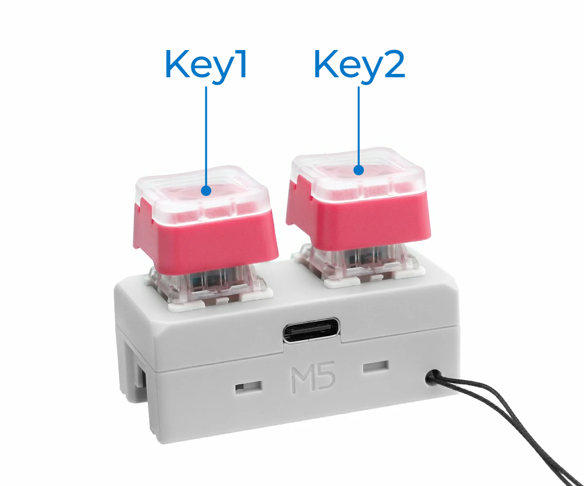
1.Button Numbering
In the factory firmware, the two buttons on Chain DualKey are named Key1 (Left Key) and Key2 (Right Key):
2.Switch Positions
- OFF USB: When the switch is in the middle position, Chain DualKey is turned off when not connected to an external power source, and operates in USB wired mode when connected (will also enable BLE and Wi-Fi).
- BLE / Wi-Fi: When the switch is toggled to the left or right, both modes function identically in this firmware, enabling BLE and Wi-Fi.
3.Connecting to Host as Keyboard
- Wired Connection: Use a USB-C cable to connect the Chain DualKey to a computer, smartphone, or other host device.
- Bluetooth Connection: Power the Chain DualKey via an external power source or toggle the switch to left / right side. On your computer, smartphone, or other host device, connect to the Bluetooth device named
DualKey-XXXX(XXXX is a four-character alphanumeric code used to distinguish different devices). When a pairing code dialog appears, simply confirm it. This firmware supports pairing and connecting to only one Bluetooth host at a time. To connect to another host, unpair it from the currently paired device first.
Chain DualKey can connect to two devices simultaneously — one via a wired connection and the other via Bluetooth.
Quit to skip it. This does not affect normal use.iOS: When an external keyboard is connected, the on-screen keyboard may be disabled in some cases, allowing input only from Chain DualKey.
Windows / Android: No specific issues have been observed; behavior may vary depending on system version and settings.
4.Configuration Web Page
Power the Chain DualKey via an external power source or toggle the switch to left / right side. On your computer or smartphone, connect to the Wi-Fi access point (SSID: DualKey_XXXX (XXXX is a four-character alphanumeric code used to distinguish different devices), Password: 12345678), then open a browser and visit 192.168.4.1 to access the configuration web page:
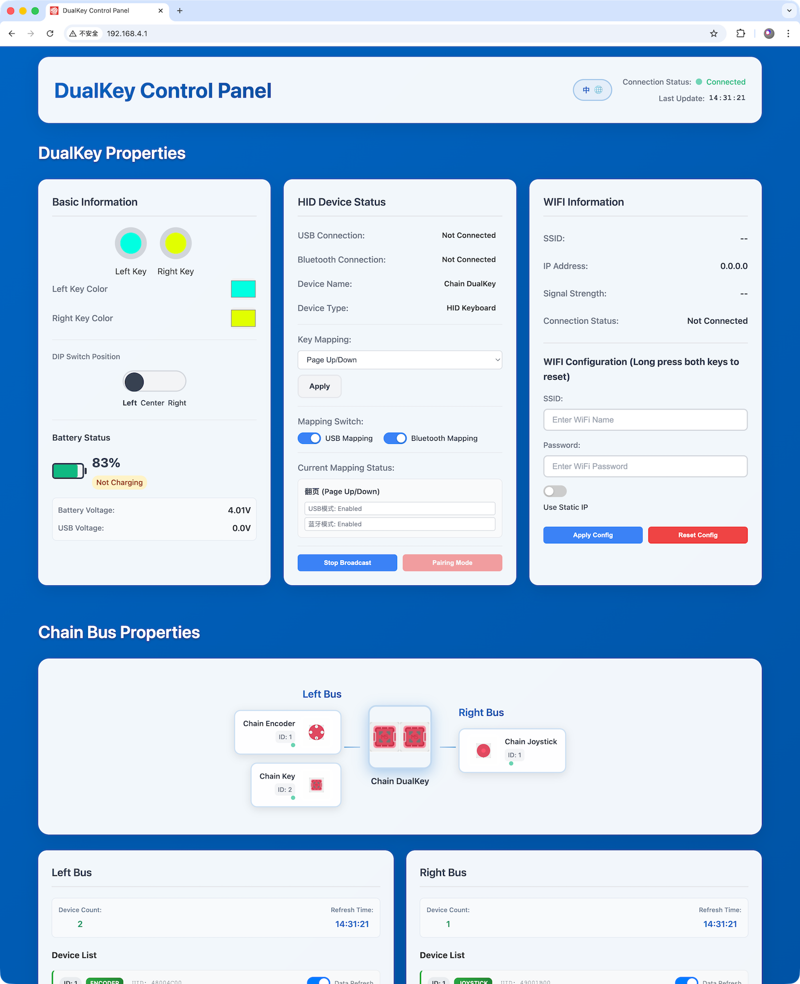
- The language of the page (Chinese / English) can be switched in the upper-right corner, where you can also check the Wi-Fi AP connection status and the latest update time.
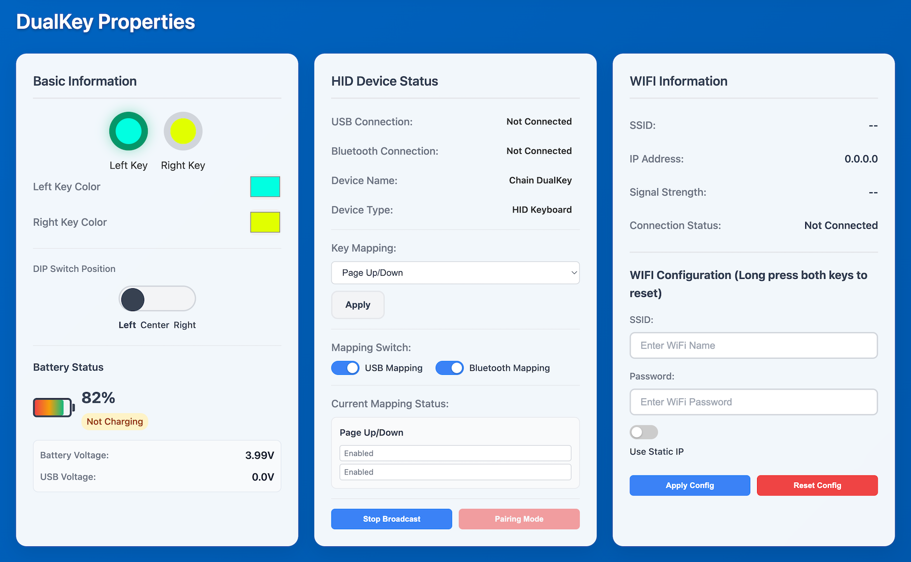
- In the middle-left Basic Information section, you can configure the LED colors of the two buttons and check button states (when pressed, the ring becomes darker, as shown below), switch position, and battery status.
If you set both button colors to pure black (0, 0, 0), the LEDs will not turn off — instead, they will display a rainbow 🌈 color cycle! - In the middle HID Device Status section, you can set button functions, enable or disable USB wired mapping and BLE wireless mapping, and check USB and Bluetooth connection status:
- Copy Paste: Simulates Ctrl+C / Ctrl+V shortcuts for copy and paste on Windows.
- Copy Paste: Simulates Cmd+C / Cmd+V shortcuts for copy and paste on macOS.
- Undo Redo: Simulates Ctrl+Z / Ctrl+Y shortcuts for undo and redo in certain Windows applications.
- Undo Redo: Simulates Cmd+Z / Cmd+Y shortcuts for undo and redo in certain macOS applications.
- Undo Redo: Simulates Cmd+Z / Cmd+Shift+Z shortcuts for undo and redo in certain macOS applications.
- Tab Switch: Simulates Ctrl+Tab / Ctrl+Shift+Tab shortcuts for switching tabs in applications (such as Chrome) on both Windows and macOS.
- Window Switch: Two keys simulate Alt and Tab. Holding Alt and pressing Tab repeatedly switches windows on Windows.
- Window Switch: Two keys simulate Cmd and Tab. Holding Cmd and pressing Tab repeatedly switches applications on macOS.
- Zoom: Simulates Ctrl+Minus / Ctrl+Plus shortcuts for zooming out and in on Windows.
- Zoom: Simulates Cmd+Minus / Cmd+Plus shortcuts for zooming out and in on macOS.
- Page: Simulates PgUp / PgDn page navigation keys for scrolling up and down on Windows and macOS.
- Volume Control: Simulates Volume Up / Volume Down keys on Windows and macOS.
- Media Control: Simulates Previous Track / Next Track media control keys on Windows and macOS.
- Media Control: Simulates PlayPause / Stop media control keys on Windows and macOS.
- Home Key: Simulates Home / End keys.
- Arrow Keys: Simulates Up / Down arrow keys.
- Arrow Keys: Simulates Left / Right arrow keys.
Some of the above options also support Android and iOS; actual availability may vary by application and system.
- In the middle-right Wi-Fi section, you can configure the Wi-Fi network for Chain DualKey to connect to. Enter the SSID, password, and static IP address, then click Apply. Chain DualKey will disable AP mode and connect to the specified network. You can then access the configuration page from the assigned IP address via computer or smartphone.
5.Chain Bus
Chain DualKey can connect to other Chain series devices—such as Chain Key and Chain Joystick—through the Chain Bus on either side. (More Chain series devices will be released soon.)
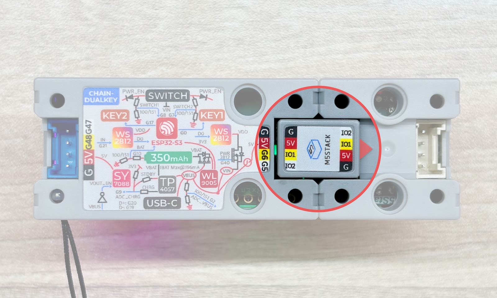
Devices in the Chain series can be connected via Chain Bridge or Chain Return. When connecting, pay attention to the direction: the triangle arrow at the bottom of each device should point outward from the Chain DualKey (the main controller), as shown below:
At the bottom of the configuration web page, you can view and configure the functions of all devices connected to the Chain Bus:
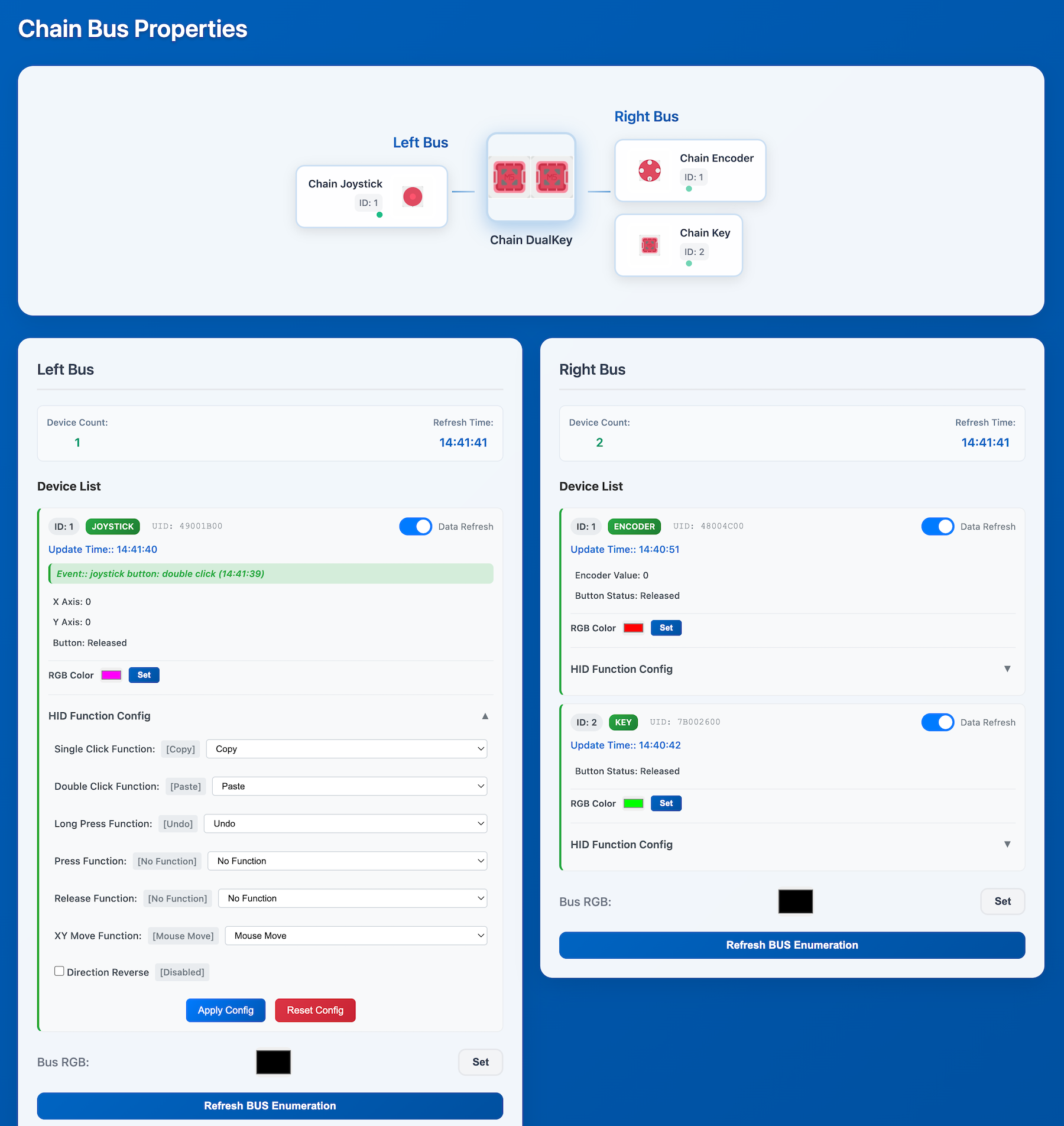
- Click a device in the top topology diagram to quickly jump to its corresponding section in the detailed device list below.
- Each device's detail card shows the latest triggered events and collected data values, and allows you to adjust the indicator LED color.
- Click HID Function Config to assign functions to various trigger events. Note that some trigger events may conflict with each other (especially Press, Release, and other button events). Be careful when assigning functions.
- When a device generates a trigger event or data update, its detail card will flash.
- Bus RGB refers to the indicator LED color for all devices on that Chain Bus (one side of the Chain DualKey).